| Sun Netra CP3240 Switch User’s Guide |
| C H A P T E R 6 |
|
Configuring Port Channels by Link Aggregation |
This chapter describes how to use the Link Aggregation feature to configure port-channels via the CLI and the Graphical User Interface.
This chapter contains the following topics:
The Link Aggregation (LAG) feature allows the switch to treat multiple physical links between two end-points as a single logical link called a port-channel. All of the physical links in a given port-channel must operate in full-duplex mode at the same speed.
You can use the feature to directly connect two switches when the traffic between them requires high bandwidth and reliability, or to provide a higher bandwidth connection to a public network.
You can configure the port-channels as either dynamic or static. Dynamic configuration uses the IEEE 802.3ad standard, which provides for the periodic exchanges of LACPDUs. Static configuration is used when connecting the switch to an external switch that does not support the exchange of LACPDUs.
The feature offers the following benefits:
Management functions treat a port-channel as if it were a single physical port.
You can include a port-channel in a VLAN. You can configure more than one port-channel for a given switch.
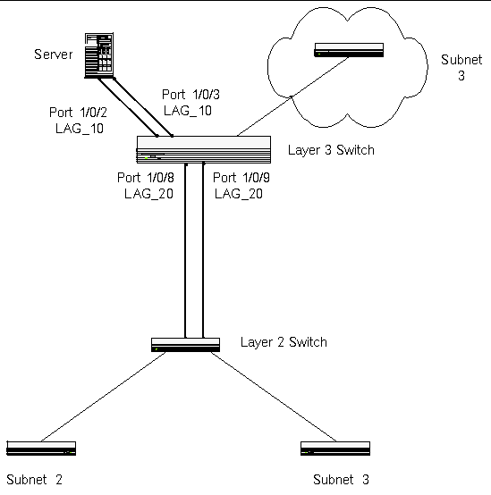
The following LAG Port Channel Example Network Diagram shows an example of configuring the software to support Link Aggregation (LAG) to a server and to a Layer 3 switch.
FIGURE 6-1 LAG Port Channel Example Network Diagram
(DTI SWITCH) #config (DTI SWITCH) (Config)#port-channel lag_10 (DTI SWITCH) (Config)#port-channel lag_20 (DTI SWITCH) (Config)#exit |
Use the show port-channel all command to show the logical interface ids you will use to identify the port-channels in subsequent commands. Assume that lag_10 is assigned id 1/1 and lag_20 is assigned id 1/2.
By default, the system enables link trap notification.
(DTI SWITCH) #config (DTI SWITCH) (Config)#port-channel adminmode all (DTI SWITCH) (Config)#exit |
At this point, the LAGs could be added to the default management VLAN.
To perform the same configuration as described in the previous CLI sections, use: Switching --> Link Aggregation --> Configuration on the Web interface.
To create the port-channels, specify port participation and enable Link Aggregation (LAG) support on the switch.
| Sun Netra CP3240 Switch User’s Guide | 820-3252-11 |
© 2007 Diversified Technology, Inc. All Rights Reserved. © 2009 Sun Microsystems, Inc. All rights reserved.