| C H A P T E R 8 |
|
Configuring VLANs |
This chapter explains virtual local area networks (VLANs) in detail and provides configuration instructions and examples. This chapter contains the following sections:
VLANs enable you to split your physical LAN into logical subparts, providing an essential tool for increasing the efficiency and flexibility of your network.
VLANs are commonly used to separate groups of network users into manageable broadcast domains, to create logical segmentation of workgroups, and to enforce security policies among each logical segment. Each defined VLAN behaves as its own separate network. The traffic and broadcasts of each VLAN are isolated from the others, increasing the bandwidth efficiency within each logical group.
Although VLANs are commonly used to create individual broadcast domains or separate IP subnets, it can be useful for a server to have a presence on more than one VLAN simultaneously. Several Sun products support multiple VLANs on a per port or per interface basis, allowing very flexible network configurations.
With multiple VLANs on an ExpressModule, a server with a single ExpressModule can have a logical presence on multiple IP subnets. By default, 128 VLANs can be defined for each VLAN-aware ExpressModule on your server. However, you can increase this number by changing the system parameters.
If your network does not require multiple VLANs, you can use the default configuration, in which case no further configuration is necessary.
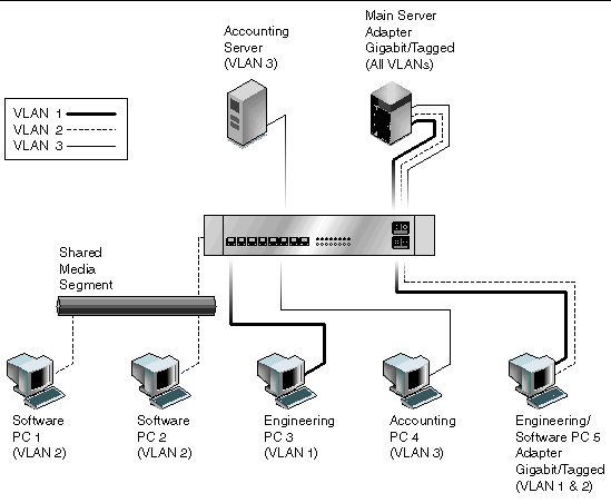
FIGURE 8-1 shows an example network that uses VLANs.
FIGURE 8-1 Example of Servers Supporting Multiple VLANs With Tagging Adapters

The example network has the following features:
The physical LAN network consists of a switch, two servers, and five clients. The LAN is logically organized into three different VLANs, each representing a different IP subnet.
The Main Server is a heavily used server that needs to be accessed from all VLANs and IP subnets. The server has a Sun Dual 10GbE XFP PCIe ExpressModule installed. All three IP subnets are accessed by means of the single physical ExpressModule interface. The server is attached to one of the switch’s Gigabit Ethernet ports, which is configured for VLANs 1, 2, and 3. Both the ExpressModule and the connected switch port have tagging turned on. The tagging VLAN capabilities of both devices enable the sever to communicate on all three IP subnets in this network, yet continue to maintain broadcast separation among the three subnets. The following list describes the components of this network:
VLAN tagging must be enabledin the following circumstances:
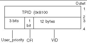
VLANs can be created according to various criteria, but each VLAN must be assigned a VLAN tag or VLAN ID (VID). The VID is a 12-bit identifier between 1 and 4094 that identifies a unique VLAN. For each network interface (nxge0 and nxge1), 4094 possible VLAN IDs can be selected per port for up to 4 ports.
Tagging an Ethernet frame requires adding a tag header to the frame. Insert the header immediately following the destination MAC address and the source MAC address. The tag header consists of two bytes of Ethernet Tag Protocol identifier (TPID, 0x8100) and two bytes of Tag Control Information (TCI). FIGURE 8-2 shows the Ethernet tag header format.
FIGURE 8-2 Ethernet Tag Header Format

By default, a single VLAN is configured for every port. This configuration groups all ports into the same broadcast domain, just as if there were no VLANs at all. VLAN tagging for the switch port is turned off.
| Note - If you configure a VLAN virtual device for an ExpressModule, all traffic sent or received by that ExpressModule must be in VLAN-tagged format. |
|
1. Create one hostname.nxgenumber file for each VLAN that will be configured for each ExpressModule on the server.
Use the following naming format, which includes both the VID and the physical point of attachment (PPA):
VLAN logical PPA = 1000 * VID + Device PPA
nxge123000 = 1000*123 + nxge
This format limits the maximum number of PPAs (instances) you can configure to 1000 in the /etc/path_to_inst file.
For example, on a server with the Sun Dual 10GbE XFP PCIe ExpressModule having an instance of 0, belonging to a member of two VLANs (with VID 123 and 224), you would use nxge123000 and nxge224000, respectively, as the two VLAN PPAs.
2. Use the ifconfig(1M) to configure a VLAN virtual device.
The output of ifconfig -a on a system having VLAN devices nxge123000 and nxge224000:
3. On the switch, set VLAN tagging and set VLAN ports to coincide with the VLANs you have set up on the server.
Using the examples in Step 2, you would set up VLAN ports 123 and 224 on the switch.
Refer to the documentation that came with your switch for specific instructions for setting VLAN tagging and ports.
|
1. Ensure that the nxge module is loaded:
2. Plumb the Sun Dual 10GbE XFP PCIe ExpressModule interface:
where xxx.xxx.xx.xxx = the IP address of the interface.
4. Add the VLAN instance (VID):
5. Configure the nxge VLAN (eth2 in this example):
where xxx.xxx.xx.xxx = the IP address of the interface.
Copyright © 2008 Sun Microsystems, Inc. All Rights Reserved.