| Sun Dual Port 4x DDR IB Host Channel Adapter PCIe User’s Guide |
| Sun Dual Port 4x DDR IB Host Channel Adapter PCIe User’s Guide |
| A P P E N D I X B |
|
Instructions for Replacing a Tall Bracket with a Short Bracket on IB-HCA card |
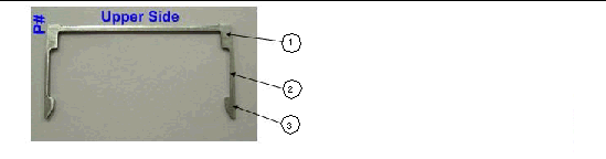
FIGURE B-1 shows the bracket-side view of a dual-port IB-HCA card.
FIGURE B-1 Tall Bracket Of The Dual Port 4x DDR IB PCIe Host Channel Adapter

The connector retention clips are used to hold the short or tall bracket in place on the card. Before the bracket can be replaced, the connector retentions clips have to be removed. FIGURE B-2 shows a connector retention clip and the designated names of its sections.
FIGURE B-2 Connector Retention Clip
a. Using a small flat head screwdriver, gently push up one hook of a connector’s clip toward the connector’s top side as shown in FIGURE B-3 (1).
b. Push the other hook each of the two clip’s hook towards the connector’s top side - as shown in FIGURE B-3 (2).
c. Finally, pull the clip away from its center - as shown in FIGURE B-3 (3).
FIGURE B-3 Extracting Connector Clip

d. Repeat the above actions for the second connector’s clip.
a. Unscrew both screws from the card using a torque screwdriver as shown in FIGURE B-4.
FIGURE B-4 Unscrew Bracket Screws

a. Grip the bracket as shown in FIGURE B-5 placing your thumb on the LED component. In a rotating move toward the component side of the card, slide the bracket out of the connectors.
b. Gently hold your thumb on the LED component as shown in FIGURE B-5, bubble 2. At the same time extract the bracket, while making sure to protect the LEDs.
c. Detach the tall bracket in a rotating move as shown in FIGURE B-5, bubble 3.
FIGURE B-5 Removing the Tall Bracket

|
1. Place Short Bracket onto Card
a. Gently place the bracket onto the card fitting the connectors through the bracket connector holes. Make sure the LEDs are aligned into their intended bracket holes.
FIGURE B-6 Place Short Bracket onto Card

2. Attach Short Bracket to Card
a. Insert a screw along with a washer into each of the two holes on the card intended for holding the bracket as shown in FIGURE B-7. Use a torque screwdriver to apply up to 2 lbs-in torque on each screw.
FIGURE B-7 Attach Bracket onto Card using Screws

a. Gently push one clip onto the connector. Make sure to slide both clip hooks (sides) around the connector evenly as shown in FIGURE B-8.
FIGURE B-8 Sliding Connector Clip Evenly

b. Use a small flat head screwdriver to gently slide the clip's hook towards the connector's base side as shown in FIGURE B-9.
FIGURE B-9 Fix Clip Hooks into Place Using Screwdriver

c. Repeat this step for the second clip. See FIGURE B-10.
FIGURE B-10 Assembled Short Bracket View

| Sun Dual Port 4x DDR IB Host Channel Adapter PCIe User’s Guide | 820-3523-10 |
Copyright © 2008, Sun Microsystems, Inc. All Rights Reserved.
 To Assemble a Short Bracket