Editing the Configuration
To display the Configuration window, click the Configuration tab. The Configuration window contains six definition windows. A tab appears for each one when you display the Configuration window. The definitions can be configured in any order but should be completed in sequence from left to right to avoid forward references to other definitions:
-
Interfaces
-
URL Groups
-
Subnet and Host Groups
-
Services
-
Filters
-
Classes
To display a definition window, click its tab.
Defining Interfaces
The Interface definition specifies an interface device name, its flow direction, and the bandwidth to be associated with it.
Figure 5-1 Interfaces Window
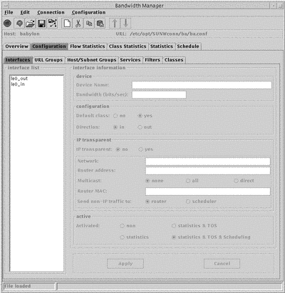
The Interface List in the left hand column displays all the currently configured interface device names. To display configuration information for an interface, click its name. The relevant parameters and values are displayed in the interface panel.
The configurable parameters are:
-
Device Name.
A new interface is created with the temporary name new. To change this name, type a new name in the Device Name field and click Apply. The device name must follow the Solaris convention of driver name, driver number. For example qe0.
The Device Name is automatically appended with _in or _out depending on the flow direction selected.
-
Bandwidth.
This is the operating bandwidth rate associated with the device, in bits per second. This value need not necessarily be the maximum of which the device is capable. The value should not exceed the device's maximum.
Note -Consider the actual operating rate of the device, rather than the nominal rate when determining the value of the bandwidth rate.
-
Default Class.
Yes
Create a default class.
No
There is no default class.
-
Flow Direction.
In
The hierarchy below this interface will regulate incoming traffic only.
Out
The hierarchy below this interface will regulate outgoing traffic only.
Depending on your selection, the interface device name is automatically appended with _in or _out.
-
IP Transparency Mode.
Yes
Use Solaris Bandwidth Manager in IP-transparent mode.
No
Use Solaris Bandwidth Manager in Non-transparent mode.
If you choose to run Solaris Bandwidth Manager in IP-transparent Mode, you must complete the additional options in the panel below:
-
Network Device.
This is the name of the device used to communicate with the network, as opposed to the router.
-
Router Address
This a list of IP addresses (or hostname) of the router. If you specify more than one address, separate them with a comma.
-
Multicast
The Mulicast option defines how multicast packets are forwarded:
-
Router MAC
This is the MAC address of the router which can be expressed in the standard hexadecimal format.
-
SendNon-IP traffic to:
This option defines how non-IP packets are forwarded:
scheduler
All non-IP packets are classified and scheduled
router
All non-IP packets are forwarded directly, not through ipqos. These packets are not logged in the flow statistics
-
-
Statistics Logging.
statistics
Statistics are collected on the interface, with the classifier running but not the scheduler.
statistics and TOS
Statistics are collected on the interface, with the Type of Service activated and the classifier running, but not the scheduler.
statistics and TOS and scheduler
Statistics are collected on the interface, with the classifier and scheduler running.
You can also use the Interface window to disable Solaris Bandwidth Manager. Select No in the Active panel.
Defining URL Groups
The URL Group definition is a list of one or more URLs (Uniform Resource Locator). These are typically made use of in the URL block of the Filter definition. See "Filter Definition".
Figure 5-2 URL Group Window
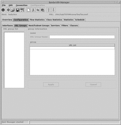
The URL Group list in the left hand column displays all the currently configured URL groups. To display configuration information for a particular URL group, click its name.
The configurable parameters are:
-
URL Group Name.
The name of the URL group.
-
Group
The list of URL group members.
To add a definition to the URL group:
-
Double-click the empty line below the last URL entry.
The text editing mode starts, indicated by a cursor in the empty line.
-
Type the URL you want to include in the URL group.
Specify the URLs in the format protocol://username:password@host:port/path where:
-
username is the login of a user
-
password is the password corresponding to the user login
-
protocol is the transport protocol used. For example, http, ftp, nntp
-
host is the host machine. You can use an asterisk (*) as a wildcard to include a particular pattern, for example, *.sun.com
-
port is the port used. You can use an asterisk (*) to indicate any protocol. If no value is specified, 80 is used.
-
path is the path of the URL. You can use an asterisk (*) as a wildcard to include a particular pattern, for example, *.htm.
-
-
Click Apply.
Configuring Host and Subnet Groups
A host or subnet group is a list of IP addresses (in dotted decimal format) or of host names that will be resolved by the systems host's database or networks table. A subnet group also contains a subnet mask.
Figure 5-3 Host and Subnet Group Window
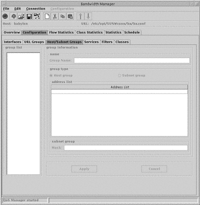
The Group List in the left hand column displays all the currently configured Host and Subnet groups. Configurable parameters are:
-
Group name
Assign a new group name when you create the group.
-
Group Type
This can be either Host or Subnet
-
Address List
The list of addresses that compose the group.
-
Subnet mask
The subnet mask. This is only required for a subnet group. This must be expressed in IP dotted notation, or as a name that can be resolved by the system's host table.
To add an address to a host or subnet group:
-
From the Group List, select the group you want to add an address to.
The addresses currently contained in the group are displayed in the adjacent address list panel.
-
In the Address List panel, double-click in the empty line below the last address entry.
The text editing mode starts, indicated by a cursor in the empty line.
-
Type the address you want to include in the group.
The address can be specified as a hostname or IP address.
-
Click Apply.
The address is added to the group.
Defining Services
A service definition provides a mapping between a service defined in application layer terms and the protocol and ports used. A number of services are pre-defined in the file /opt/SUNWconn/ba/lib/services.def. You do not need to carry out any configuration to use these services. "Configuration Examples" shows the pre-defined classes.
Figure 5-4 Services Window
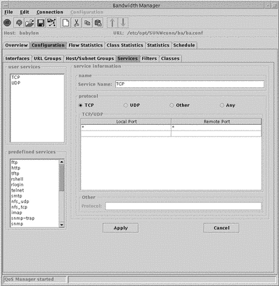
The Services Lists in the left hand column display all the currently configured services. The configurable parameters for user defined services are:
-
Service Name
New services are created with the temporary name new. To change this name, type a new name in the Service Name field and click Apply.
-
Protocol
Choose one of TCP, UDP, Other or Any.
-
Local and Remote Port.
-
Other
Specify the protocol you want to use here.
You need only complete this field if you specified Other in the Protocol field.
To add port information:
-
From the Services List, select the service you want to add port information to.
The service is highlighted. The ports currently used by the service are displayed in the TCP/UDP panel.
-
In the TCP/ UDP panel, double-click in the empty line below the last address entry. Complete both the Local and Remote port columns.
The text editing mode starts, indicated by a cursor in the empty line.
-
Type the ports you want to include in the Service.
Use an asterisk (*) to indicate any port.
-
Click Apply.
The port information is added to the service.
Defining Filters
The filter definition contains local and remote information and a service, and is used to determine the class of a packet. It can also contain URL information and a Type of Service value.
Figure 5-5 Filters Window
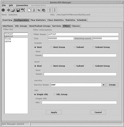
The Filter List in the left hand column displays all the currently configured Filters. The configurable parameters are:
-
Filter Name
New filters are created with the temporary name new. To change this name, type a new name in the Filter Name field and click Apply.
-
TOS
In the TOS field, type the Type of Service value. This must be a value between 0 and 255.
-
Matching mask
This value specifies which bits will match the Type of Service value in the IP header with the Type of Service value. This must be specified as a bitmask.
-
Remote and local network entity types.
Specify the remote and local network entity types. For each type, a different name field is displayed:
Host
Complete the Host Name field. This value can be expressed as a domain name or IP address.
Host Group
Complete the Host Group Name field with a Host Group name defined in the Host and Subnet Groups window. To define a new Host Group, click Create. This starts the Host and Subnet Groups window.
Subnet
Complete the Subnet Name field with a Host name or IP address. Complete the Subnet Mask field with a subnet mask.
Subnet Group
Complete the Subnet Group Name field with a Subnet Group name defined in the Host and Subnet Groups window. To define a new Subnet Group, click Create. This starts the Host and Subnet Groups window.
-
Service
The available services are displayed in the drop-down menu. To define a new service in the Services window, click Create.
-
URL
From the local panel, select Single URL or URL Group. A different name field is displayed for each selection:
Single URL
Complete the Single URL field. Specify the URL in the format protocol://username:password@host:port/path.
URL Group
Complete the Group Name field with a URL group name defined in the URL Group window.
To define a new URL Group, click Create. This starts the URL Group window.
Defining Classes
A class definition contains the parameters for the class, including the filters that cause packets to be placed in this class.
Figure 5-6 Classes Window
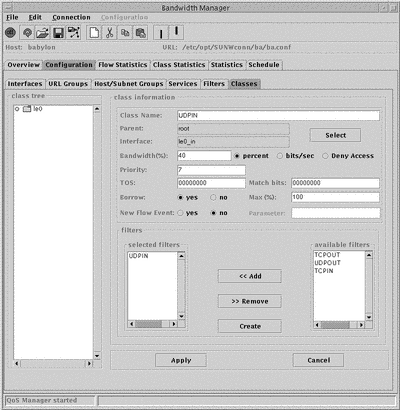
The classes are displayed as an expandable tree structure in the Class Tree, together with the interface name and the flow direction. Classes that contain other classes are displayed as folders.
The definitions are presented as a hierarchy, from left to right, in the following order:
-
Interface name
-
Interface flow direction
-
Class, sibling class
-
Child class
The parameters and values for each class are displayed in the adjacent class panel.
New classes are added as a child or sibling of the currently selected class. Use the Edit menu to choose which. A new class is created with the temporary name new. To change this name, type a new name in the Class Name field and click Apply.
The configurable parameters for a class are:
-
Bandwidth
You can specify this as a percentage, or in bits per second. You can also specify that this class is not allocated any bandwidth, by choosing Deny Access.
-
Priority
This must be a value between 1 (highest priority) and 7 (lowest priority).
-
Type of Service (TOS)
-
Match bits
This value specifies which Type of Service bits in the IP header will be modified with the Type of Service value. This must be specified as a bitmask.
-
Borrow bandwidth
If you select Yes, complete the Max % field with the maximum bandwidth the class is allowed to borrow.
-
Directory request
If you select Yes, complete the Flow Event field with the flow events to be generated when a new flow is detected in the class. For more information on Flows, see "Flows".
-
Filter
This determines what network traffic will be allocated to this class. If you do not specify any filters, no traffic is allocated. To create a new filter, click Create.
- © 2010, Oracle Corporation and/or its affiliates
