This appendix contains descriptions of the system connectors.
The connectors described are:
-
The SCSI connector (internal)
-
The keyboard/mouse connector
-
The memory expansion connector
-
The diskette drive connector
-
The serial port connectors
-
The serial port mode jumpers

Figure E-1
Ethernet connector
Table E-1
Table of pin functions for the Ethernet connector
Pin Function
1 N.C.
2 Collision (+)
3 Transmit Data (+)
4 N.C.
5 Receive Data (+)
6 Ground
7 N.C.
8 N.C.
9 Collision (-)
10 Transmit Data (-)
11 N.C.
12 Receive Data (-)
13 +12 VDC
14 N.C.
15 N.C.

Figure E-2
The SCSI connector (external)
Table E-2
Table of pin descriptions for the SCSI connector (external)
Pin Description Pin Description
1 Ground 26 sd0*
2 Ground 27 sd1*
3 Ground 28 sd2*
4 Ground 29 sd3*
5 Ground 30 sd4*
6 Ground 31 sd5*
7 Ground 32 sd6*
8 Ground 33 sd7*
9 Ground 34 sdp*
10 Ground 35 Ground
11 Ground 36 Ground
12 Ground 37 Ground
13 Ground 38 +5 VDC
14 Ground 39 Pullup-4
15 Ground 40 Ground
16 Ground 41 atn*
17 Ground 42 N.C.
18 Ground 43 bsy*
19 Ground 44 ack*
20 Ground 45 rst*
21 Ground 46 msg*
22 Ground 47 sel*
23 Ground 48 cd*
24 Ground 49 req*
25 Ground 50 io*
Pin 38 is fused and through a diode.

Figure E-3
The SCSI connector (internal)
Table E-3
Table of SCSI connector (internal) pin functions
Pin Description Pin Description
1 Ground 26 +5 VDC
2 sd0* 27 N.C.
3 Ground 28 N.C.
4 sd1* 29 Ground
5 Ground 30 Ground
6 sd2* 31 Ground
7 Ground 32 atn*
8 sd3* 33 Ground
9 Ground 34 N.C.
10 sd4* 35 Ground
11 Ground 36 bsy*
12 sd5* 37 Ground
13 Ground 38 ack*
14 sd6* 39 Ground
15 Ground 40 rst*
16 sd7* 41 Ground
17 Ground 42 msg*
18 sdp* 43 Ground
19 Ground 44 sel*
20 Ground 45 Ground
21 Ground 46 cd*
22 Ground 47 Ground
23 N.C. 48 reg*
24 N.C. 49 Ground
25 N.C. 50 io*
Pin 26 is fused and through a diode.

Figure E-4
The audio connector (Din-8)
Table E-4
The audio connector pin descriptions
Pin Description
1 N.C.
2 N.C.
3 ain-
4 N.C.
5 N.C.
6 ain+
7 shield
8 audio out
Note -
ISDN is not supported in the SPARCstation IPX

Figure E-5
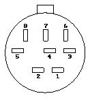
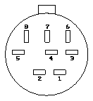
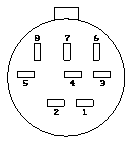
The keyboard/mouse connector
Table E-5
Table keyboard/connector pin descriptions
Pin Description
1 Ground
2 Ground
3 +5 VDC
4 Mouse In
5 Keyboard Out
6 Keyboard In
7 Ground
Note -
All Signals TTL Levels. +5V current-limited.

Figure E-6
The memory expansion connector
Table E-6
Table of memory expansion connector pins and descriptions
Pin Description
1 PA26
2 RamClk1
3 RamSel1*
4 GND
5 ParCS1
6 RamClk
7 PA25

Figure E-7
The diskette drive connector
Table E-7
Table of diskette drive connector pin descriptions
Pin Description Pin Description
1 eject 18 direction
2 N.C. 19 Ground
3 Ground 20 step
4 ? 21 Ground
5 Ground 22 write data
6 N.C. 23 Ground
7 Ground 24 write gate
8 Index 25 Ground
9 Ground 26 track 0
10 drive select 0 27 Ground
11 Ground 28 write protect
12 N.C. 29 Ground
13 Ground 30 read data
14 N.C. 31 Ground
15 Ground 32 hd select
16 motor 33 Ground
17 Ground 34 disk change

Figure E-8
The SBus connector
A table of SBus connector pins and descriptions can be found on the next page.
Table E-8
Table of SBus connector pins and descriptions
Pin Description Pin Description Pin Description
1 Ground 33 sb_a(6) 65 sb_d(18)
2 sb_br* 34 sb_a(8) 66 sb_d(20)
3 sb_sel* 35 sb_a(10) 67 sb_d(22)
4 sb_irq1* 36 sb_err* 68 Ground
5 sb_d(0) 37 sb_pa(12) 69 sb_d(24)
6 sb_d(2) 38 sb_pa(14) 70 sb_d(26)
7 sb_d(4) 39 sb_pa(16) 71 sb_d(28)
8 sb_irq2* 40 sb_ack8* 72 +5 VDC
9 sb_d(6) 41 sb_pa(18) 73 sb_d(30)
10 sb_d(8) 42 sb_pa(20) 74 sb_siz(1)
11 sb_d(10) 43 sb_pa(22) 75 sb_rd
12 sb_irq3* 44 sb_ack32* 76 Ground
13 sb_d(12) 45 sb_pa(24) 77 sb_a(1)
14 sb_d(14) 46 sb_pa(26) (GND) 78 sb_a(3)
15 sb_d(16) 47 N.C. 79 sb_a(5)
16 sb_irq4* 48 -12 VDC 80 +5 VDC
17 sb_d(19) 49 sb_clk 81 sb_a(7)
18 sb_d(21) 50 sb_bg* 82 sb_a(9)
19 sb_d(23) 51 sb_as* 83 sb_a(11)
20 sb_irq5* 52 Ground 84 Ground
21 sb_d(25) 53 sb_d(1) 85 sb_pa(13)
22 sb_d(27) 54 sb_d(3) 86 sb_pa(15)
23 sb_d(29) 55 sb_d(5) 87 sb_pa(17)
24 sb_irq6* 56 +5 VDC 88 +5 VDC
25 sb_d(31) 57 sb_d(7) 89 sb_pa(19)
26 sb_siz(0) 58 sb_d(9) 90 sb_pa(21)
27 sb_siz(2) 59 sb_d(11) 91 sb_pa(23)
28 sb_irq7* 60 Ground 92 Ground
29 sb_a(0) 61 sb_d(13) 93 sb_pa(25) (GND)
30 sb_a(2) 62 sb_d(15) 94 sb_pa(27) (GND)
31 sb_a(4) 63 sb_d(17) 95 sb_reset*
32 sb_merr* 64 +5 VDC 96 +12 VDC

Figure E-9
The power connector
Table E-9
Table of power connector pins and descriptions
Pin Description
1 +5 VDC
2 +5 VDC
3 Ground
4 Ground
5 +12 VDC
6 POK
7 +5 VDC
8 +5 VDC
9 Ground
10 Ground
11 +12 VDC
12 -12 VDC

Figure E-10
The speaker connector.
Table E-10
Table of speaker connector pins and descriptions
Pin Description
1 Speaker+
2 Speaker-

Figure E-11
The Serial port (ttya/ttyb)
Table E-11
Table of serial port (ttya/ttyb) pins and descriptions
Pin Description
1 DTR
2 CTS/TRxC
3 TxD
4 Ground
5 RxD
6 RTS
7 DCD
8 RTxC
The pair of three-pin jumpers located near U0512 (the MK48T02) switch the
serial ports' output levels between RS232 (+/- 12V) to RS423 (+/- 5V). To
change this setting, move both jumpers together as shown in the following
drawing.

Figure E-12
The jumpers
SPARCstation IPX systems are normally configured for RS423 operation.

Figure E-13
The video connector
Table E-12
Table of video connector pins and descriptions
Pin Description
A1 Video-Red
A2 Video-Green
A3 Video-Blue
1 Ground
2 Ground
3 Sense(2)
4 Ground
5 Composite Sync
6 Ground
7 Ground
8 Sense(1)
9 Sense(0)
10 Ground


