
Before you perform the procedures in this chapter, be sure that you have read
and performed the procedures in Chapters 1 and 2. This chapter assumes that
a primary memory board is already installed in your system, and that you are
now adding memory by installing a secondary memory board.

Caution - Do not touch the components on the boards or any metal parts.
Wear a grounding strap when handling the boards. Do not disconnect the
power cord from the system unit's power receptacle. The power cord should
be left plugged in to a grounded power outlet. This connection provides the
ground path necessary so that you can safely remove and install printed circuit
boards and other components. Be sure that the system unit's power is turned
off by observing that the green light-emitting diode (LED) at the front of the
chassis is not lit and the fan in the power supply is not running.
1. Remove the flex-circuit cable (J0101) from the main-logic board (J0705) by
pulling upwards on the flex-circuit cable's extraction loop.
See Figures 3-1 and 3-2.

Figure 3-1
Flex-circuit Cable

Caution - The flex-circuit cable's extraction loop is not to be used to remove
the primary board or a two-board set.

Figure 3-2
Removing the Flex-circuit Cable (J0101) from the Main-logic Board (J0705)
2. Lift up carefully on the edge of the primary memory board so that the
SBus pins are disengaged.
a. Completely remove the primary memory board.

For additional information, see "Removal Procedure" in Appendix B.
b. Disconnect the flex-circuit cable (J0102) from the primary memory
board (J401).

3. Place the primary memory board on an anti-static surface (e.g., a tabletop
covered with a piece of anti-static foam).
4. Turn the primary memory board over so that you can see where the
retainer mounts to the board.
The retainer mounts are located on the "bottom" side of the board next to
the board's SBus slot plug pins. See Figure 3-3.
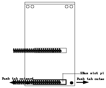
Figure 3-3
Removing Board Retainer
5. Using your finger, gently push the retainer mounting tab outward and
from the other side pull the tab free of the board.
There are two mounting tabs. Perform this step for each tab so that the
retainer is completely removed from the board. Set the retainer aside for
possible future reuse.
6. Turn the primary memory board upwards so that the surface showing the
controller (U100) faces you.

7. Be sure that the four nylon spacer posts are installed on the secondary
memory board.
See Figure 3-4.

Figure 3-4
Finding the Nylon Spacer Posts
8. Join the secondary memory board with the primary memory board,
paying particular attention to proper fitting of:
a. Inter-board connector pins
Press the boards together so that the connectors are fully closed (the
secondary and primary connector blocks are touching) and all connector
pins are enclosed within the connectors.
b. Four nylon spacer posts
See Figures 3-4 and 3-5.
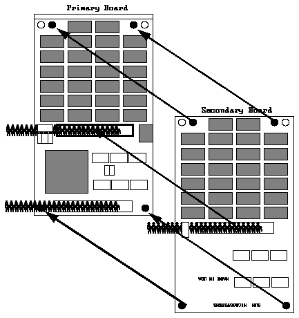
Figure 3-5
Joining the Secondary and Primary Memory Boards
9. Connect the flex-circuit cable (J0101) to the memory connector (J0705) on
the main-logic board.
10. Slide the two-board set at an angle into the back panel of the system unit.
Make sure that the mounting plate on the primary memory board hooks
into the holes on the back panel of the system unit.
The mounting holes are above the rectangular opening in the back panel.

11. When the board set is close enough to the SBus slot to permit, plug the
remaining flex-circuit cable connector (J0102) to the shrouded connector
(J401) on the primary memory board.
12. Align the board set's SBus plug with the main-logic board's SBus slot
socket.
13. Press the board set toward the rear of the system unit.
14. Gently press the plug into the socket.

Caution - Using excessive force may bend or damage the pins.
15. Turn the system unit power on, and check for proper operation of the
system unit and the installed secondary and primary memory boards.
a. Read Chapter 4 if applicable.
b. Read Chapter 5.
16. Replace the cover of your system unit.
If you are not sure how this is done, see Appendix C, "Replacing the System
Cover."
