
Follow the instructions in this manual to verify the version of the SunOS that is
installed, unpack the shipment, and install the SPARC module on the system
board. The module installation instructions are for installing a second SPARC
module into a system.
The SM100 SPARC module is designed for installation in systems that are
running SunOS Version 4.1.2 or later, Solaris 2.x, or another compatible
operating system. If you have any doubts about the version you are running,
do the following:
Identifying the UNIX Version of Your System
Execute the command that identifies the operating system and its version
number, as appropriate for your system:
1. Go to the handbook that came with your peripheral to find this UNIX
command.
2. See the section about verifying the system environment.
3. Return to this book after you execute the command.
If you are not running a compatible operating system, you will need to install
one before you continue.
1. Remove the components from the packing box. In addition to this guide,
the shipment should include:
a.
An anti-static bag containing the SPARC module.
b.
An electrostatic discharge (ESD) kit, P/N 560-1302.
Caution -

Although P/N 560-1302, ESD kit, is packaged with the SM100
SPARC module, DO NOT use P/N 560-1302 when installing the module in a
600MP-based system.
ESD kit P/N 250-1088, containing the Sun ESD mat, is required when
installing the SPARC module in a 600MP-based system.
2. Save the packing box and packing materials in case you need to transport
the module.
Do not open the bag containing the SPARC module until you are instructed to
do so.
Electrostatic Discharge Precautions

Caution - Circuit board components are vulnerable to damage by electrostatic
discharge (ESD). An electrostatic charge can build up on the human body and
then discharge when you touch a board. Such discharge can be produced by
walking across a carpet and touching a board, or by other similar causes. Before
handling any board, make sure you dissipate your body's charge. Touch a
conductive surface of the chassis or other element connected to common earth
ground to discharge the static electricity present in your body. To minimize risk
of ESD damage:
o Handle board by edges only.
o Store board in antistatic bag provided.
Use Sun ESD kit P/N 250-1088 (or equivalent) when working on the 600MP
System Board or the 600MP Expansion Memory Board. Sun ESD kit P/N 250-
1088 contains the Sun approved Sun ESD mat which has 0.25" of cushioning to
protect underside components, prevent board flexing, and provide ESD
protection. Instructions for use are printed on the mat.
Do NOT use ESD kit P/N 560-1302 when installing SPARCsystem 600MP
boards. ESD kit P/N 560-1302 does not provide adequate protection for
SPARCsystem 600MP boards.
Note - If installing the SM100 SPARC module in a 600MP-based system, be
sure to have the Sun ESD mat and grounding strap, P/N 250-1088, available.
If installing the SM100 SPARC module in a system that is NOT a 600MP-based
system, you may use the anti-static wrist strap and mat contained in P/N 560-
1302 that shipped with the SPARC module.
Before turning off the system power, you must halt the operating system:
1. Go to the handbook that came with your peripheral to find this procedure.
2. See the section about shutting down the system.
3. Return to this book after you perform the procedure.
Caution -

Turn off the power at the main AC breaker on the rear of the system
before you insert or remove boards and disk drives. Then, turn off the main
power at the switch on the power supply. Do not disconnect the AC power
cord from its receptacle.
Caution -

Use Sun ESD kit P/N 250-1088 (or equivalent) when installing
integrated circuits, printed circuit boards, and drives in a SPARCsystem
600MP. Follow the instructions printed on the ESD mat. Refer to the section,
"Electrostatic Discharge Precautions" for a description of the ESD mat.
Do NOT use ESD kit P/N 560-1302 when working on SPARCsystem 600MP
boards.
1. Move the system so that you have easy access to the enclosure.
2. Spread the anti-static mat - shiny side facing up - or Sun ESD mat (P/N
250-1088, ESD mat, is required for 600MP-based systems) in the area
where you are working.
3. If the system is a 56-Inch Data Center Cabinet, use a #2 phillips
screwdriver to remove the vented, rear panel. Then, go to step 6.
4. If the system is a 12-Slot Office Pedestal, go to step 6.
5. If the system is a 5-Slot Office Pedestal, remove the top cover:
a. Locate the top cover release knob. Turn the knob counter-clockwise a
1/4-turn or until you hear a click.
b. Slide the top cover back and lift the cover off of the chassis. Set the
cover aside.
6. Label the cables, including the cables that are attached to serial ports A
and B, and any cables that are connected to any SBus cards. Then, remove
all of the cables.
7. Use a 2.5 mm hexagonal allen wrench to remove the hex-socket cap screws
that are located at each end of the system board. Set the four screws aside.
8. Move the extraction lever on the system board to the open position.
9. Gently remove the system board from the enclosure, and place it on the
anti-static mat or Sun ESD mat (P/N 250-1088, ESD mat, is required for
600MP-based systems).
The SM100 dual processor module is a daughter card that is installed on the
MBus connector on the system board. Slot 0 must be installed; slot 1 is
optional.
Note -
When a SPARC module is installed in MBus slot 1, SBus slot 3 can not
be used.
See Figure 1, System Board, to locate the MBus slots.

Figure 1
System Board
Installing the SPARC Module on the System Board
To install the SPARC module in MBus slot 1 on the system board, follow the
procedures in this section.

Figure 2
Installing the Second SPARC Module in Slot 1
Remove the system board from the cardcage before proceeding. See the section
entitled "Removing the System Board from the Enclosure." Visually inspect the
pins in the MBus connector to make sure they are not bent before installing the
module.
1. Use the anti-static mat or Sun ESD mat (P/N 250-1088, ESD mat, is
required for 600MP-based systems) and grounding strap for this
procedure.
2. Remove the slotted fillister head screws from each of the standoffs.
-
Ensure that the standoffs are in the MBus slot location if you are installing a
module in MBus slot 1.
The two standoffs used for SBus slot 3 must be moved to the MBus location
if you are installing a SPARC module in MBus slot 1.
3. Hold the card by the edges near the connector.
4. Position the card over the MBus connector, ensuring that the keyed
notches on the connector match the bumps on the receiving connector.
-
Make sure the card is seated on the four standoffs.
-
Do not "rock" the module onto the connector. Ensure vertical movement of
the module during the insertion or removal process.
5. Firmly but gently press the card onto the connector until seated.
6. Replace and fasten the slotted fillister screws on the four standoffs.
Note -
Do not substitute pan head screws for the fillister head screws
originally removed from the standoffs. Fillister head screws must be used
because the head on a fillister head screw is taller (see Figure 3).

Figure 3
Fillister Head and Pan Head Screws
Caution -

Because of the tight clearance, use caution when replacing the
fillister head screws. Do not allow the screwdriver to contact with the SPARC
module component wire leads.
7. Replace the system board in the cardcage.
Follow these steps to install the system board in the enclosure:
1. Move the extraction levers on the system board to the closed position.
2. Gently replace the board in the enclosure.
3. Make sure the board connectors are firmly seated against the connectors
on the cardcage.
4. Use a 2.5 mm hexagonal allen wrench and replace the hex socket cap
screws that secure the board to the cardcage.
5. Reinstall all cables removed in step 6 on page 5.
6. If the system is a 56-Inch Data Center Cabinet, use a #1 phillips
screwdriver and replace the two screws that secure the vented rear panel
to the enclosure. Then, go to step 9.
7. If the system is a 12-Slot Office Pedestal, go to step 9.
8. If the system is a 5-Slot Office Pedestal, replace the top cover:
a. Slide the cover towards the front of the system until the tabs mate with
the retaining slots at the front and rear of the system.
b. Secure the top cover by turning the release knob clockwise a 1/4-turn
or until you hear a click.
9. Move the system to its normal operating location.
10. Remove and store the anti-static or Sun ESD mat.
Follow these steps to power-up the system:
1. Set the power switch on the chassis to the ON position.
Note -
Once Power-On-Self-Tests are completed and functional modules are
recognized, the operating system will configure itself automatically to take
advantage of all available processors.
2. Boot the system using the procedure that is appropriate for your operating
system:
a. Go to the handbook that came with your peripheral to find this
procedure.
b. See the section about booting the system.
c. Return to this book after you perform the procedure.
Watch the boot information displayed on the screen to confirm that all
processors are recognized. For a SPARCsystem 600MP running SunOS 4.x,
the message would look like:

The numbers in parenthesis, 2 x 605C, indicate the number of processors
running (two), and the revision number of the SPARC module that is
installed (605C).
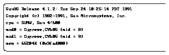
The mod0 entry and mod1 entry indicate the system recognizes one SM100
SPARC module (two processors), which is in MBus slot 0. If two SPARC
modules were installed (four processors), the system would recognize the
two modules - one in MBus slot 0 and one in MBus slot 1. Boot information
displayed for two SM100 SPARC modules would include an entry for four
processors: mod0, mod1, mod2, and mod3.
3. Wait for the system to boot. When the login: prompt is displayed, log
in and resume operations.
