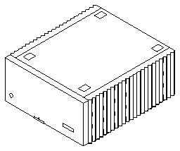

The disk tower 1000 System provides SCSI disk expansion to one or more SCSI hosts in the SPARCserver 1000 system. It features up to four disk cards - each card configured with four half-height 3.5-inch disk drives.
The disk tower 1000 System, shown in Figure 1-1, is a tabletop unit featuring front and rear component accessibility.
Figure 1-1 disk tower 1000 System
Internal system components (see Figure 1-2) are:
Figure 1-2 Internal Components
The chassis assembly, shown in Figure 1-3, consists of the:
The backplane is near the center of the chassis. This allows for the insertion and removal of system components from the system front and rear.
Figure 1-3 Chassis Assembly
The disk tower 1000 backplane provides power to the disk cards.
The power supply, shown in Figure 1-4, provides 650 watts of power. The power supply plugs directly into the backplane through two 240-pin connectors. Connection to the fan tray is provided through a single connector located on the right rear side of the power supply. This connector routes AC power to the power supply and provides DC power for the fans. The key switch should remain in the ON position at all times.
Figure 1-4 Power Supply
The fan tray, shown in Figure 1-5, provides cooling for the power supply, boards and backplane. In addition, this module routes AC power from the chassis rear to the power supply. Each fan has a temperature sensor to regulate fan speed in accordance with air temperature. DC power for the fans is obtained from the power supply via a connector in the fan tray rear. The AC power switch is on the fan tray.
Figure 1-5 Fan Tray
The disk card supports four SCSI-2 disk drives. Backplane connector J0200 mates to the system bus and brings power to the card. The card handles data and control sequentially through disks 0, 1, 2, and 3. It connects via the IN port to the SCSI host in the SPARCserver 1000 system.
The on-board DC-DC converter converts +5V backplane power to +12V DC to power the disk drives.
Each disk drive incorporates a controller board which connects with the disk card via a daughter board. The mating force of these connectors, the drive guides, and the ejector drive retainer secure the drive to the disk card.
The SCSI address for each drive is connector-assigned. The installer does not have to configure the drive address.
Disk cards are of two versions, distinguished by the number of connectors on the back panel:
Figure 1-6 SCSI-2 Disk Card Component Locations
Figure 1-7 Wide SCSI-2 Disk Card Component Locations
