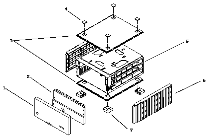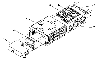
The illustrations and tables on the following pages are intended to supplement
the removal and replacement procedures described in previous chapters.
The following items for the disk tower 1000 System can be replaced at the
customer site by a qualified service provider.
Table 8-1
List of Replaceable Components
---------------------------------------------------------------------------------------------------------------------------------------------------------------------


General Category                                                 Description                                                     Part Number       Key in Table 8-2
---------------------------------------------------------------------------------------------------------------------------------------------------------------------
Exterior components                                              Front panel assembly                                            540-2477-xx       1

                                                                 EMI panel                                                       340-2943-xx       2

                                                                 Top/bottom cover                                                330-1469-xx       3, 8

                                                                 Plug, cover                                                     330-1589-xx       4

                                                                 Chassis assembly  -  includes backplane, power supply, fan      540-2273-xx       5
                                                                 tray and plastics

                                                                 Side panels                                                     330-1470-xx       6

                                                                 Foot                                                            330-1590-xx       7

                                                                                                                                                   Key in Table 8-3

DC power supply                                                  Power supply                                                    F300-1103-xx      1

Backplane assembly                                               Backplane assembly                                              F501-2021-xx      2

                                                                 Chassis enclosure                                               340-2684-xx       3

Disk card                                                        PCB assembly to accommodate four 3 1/2-inch narrow              F501-2066-xx      4
                                                                 SCSI-2 disk drives

                                                                 Disk drive, 535 Mbyte narrow SCSI-2 single connector with       F540-2403-xx      5
                                                                 bracket

Disk card                                                        PCB assembly to accommodate four 3 1/2-inch wide SCSI-2         F501-2588-xx      4
                                                                 disk drives

                                                                 Disk drive, 1.05 Gbyte wide SCSI-2, single connector with       F540-2568-xx      5
                                                                 bracket

                                                                 Air restrictor board, card cage board slot                      F540-2388-xx      6

Fan tray                                                         Fan tray                                                        F370-1547-xx      7

Note: The suffix -xx denotes the revision level of an assembly.

---------------------------------------------------------------------------------------------------------------------------------------------------------------------
Table 8-2
Parts List for Exterior Components
--------------------------------------------------------------------------------------------------


--------------------------------------------------------------------------------------------------


Key                                                              Description           Part Number
--------------------------------------------------------------------------------------------------
1                                                                Front panel assembly  540-2477-xx

2                                                                EMI panel             340-2943-xx

3                                                                Top/bottom cover      330-1469-xx

4                                                                Plug cover            330-1589-xx

5                                                                Chassis enclosure     340-2684-xx

6                                                                Side panels           330-1470-xx

7                                                                Foot                  330-1590-xx

Note: The suffix -xx denotes the revision level of an assembly.

--------------------------------------------------------------------------------------------------
Table 8-3
Parts List for Base Chassis and Backplane
-----------------------------------------------------------------------------------------------------------------------------------------------------


-----------------------------------------------------------------------------------------------------------------------------------------------------


Key                                                              Description                                                         Part Number
-----------------------------------------------------------------------------------------------------------------------------------------------------
1                                                                Power supply                                                        F300-1103-xx

2                                                                Backplane assembly                                                  F501-2021-xx

3                                                                Chassis enclosure                                                   340-2684-xx

4                                                                PCB ASSY. to accom. four 3 1/2-inch narrow SCSI-2 disk drives       F501-2066-xx

4                                                                PCB ASSY. to accom. four 3 1/2-inch wide SCSI-2 disk drives         F501-2588-xx

5                                                                Disk drive, 535 Mbyte single connect. narrow SCSI-2 with            F540-2403-xx
                                                                 bracket

5                                                                Disk drive, 1.05 Gbyte single connector, wide SCSI-2 w/bracket      F540-2568-xx

6                                                                Air restrictor board                                                F540-2388-xx

7                                                                Fan tray                                                            F370-1547-xx

Note: The suffix -xx denotes the revision level of an assembly.

-----------------------------------------------------------------------------------------------------------------------------------------------------


