
This product note pertains to Data Center Expansion Cabinets that have any
combination of rack-mounted SPARCserver(TM) 1000 or 1000E server systems
and/or SPARCstorage Array Model 100 Series systems installed.
Note -
Many Data Center Expansion Cabinet configurations require one or two
blower assemblies to be installed to provide adequate air flow and cooling.
Note -
If you are unsure of the applicability of this product note, consult with
your Sun sales department for guidelines in this matter.
Install the blower assembly in the 56-inch cabinet using these procedures.
Note -
The cabinet may be installed in a mission-critical environment requiring
a complete and thorough shutdown process to be performed. For this reason, it
is beyond the scope of this document to provide a comprehensive power-off
procedure that can cover all possible system installations.
Power off the cabinet using the correct power-off procedures described in
the service manual and/or the system administration guide for the system
that you are working on.
Warning -

The power must be turned off at the AC distribution unit before
removing system cover panels. Failure to turn power off in this way presents a
risk of electrical shock to personnel working on the cabinet.
Caution -

Do not disconnect the power cord from the facilities outlet when
working on the system. This connection provides a ground path that prevents
damage from electrostatic discharge.
All vented front panels remove in the same manner. They are retained by ball
studs on the cabinet that mate with catches on the rear side of the panel.
1. Grasp a panel under the vent at one end and pull it out far enough to just
disengage the ball studs (see Figure 1).
2. Grasp the panel at the opposite side and pull it out to disengage and
remove the panel. Set the panel aside.
3. Repeat steps 1 and 2 to remove all remaining vented front panels.
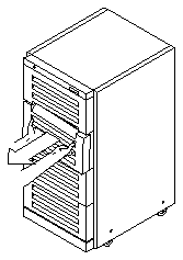
Figure 1
Removing the Vented Front Panels
1. At the panel top, remove the two screws securing the panel to the frame
(see Figure 2).
2. Tilt the top of the panel out and lift it free of the cabinet.
There is a flange on the bottom of the rear screen panel. Lift the rear screen
out of the cabinet. Set the panel aside.
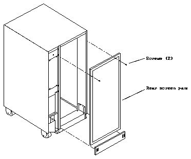
Figure 2
Removing the Rear Screen Panel
Note -
You may need to remove this panel to access to the chassis and blower
power receptacles on the rear of the power distribution unit.
1. Use the flat-blade screwdriver to unfasten the two captive screws at the
bottom of the side panel (see Figure 3).
2. Firmly grasp the outer edges of the side panel with both hands and lift up
on the panel to release the catches at the top.
Set the panel aside.

Figure 3
Removing the Right Side Panel
Remove any existing blowers or fans before installing the blower assembly.
1. Unplug the power cords:
a. Locate the fan(s) and trace the power cords to the power sequencer.
See Figure 4.
b. Unplug the cords and cut all tie wraps securing the cords to the rack.
2. Remove screws securing each fan assembly in place and remove the fan(s)
along with their power cords.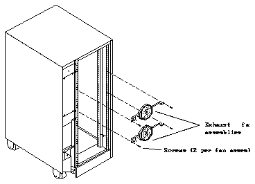
Figure 4
Removing the Exhaust Fan Assemblies
1. Remove the top two vented front panels.
2. Remove the small EMI panel in the upper-right area of the cabinet.
3. Locate the blower assembly.
See Figure 5.
4. Plug the female end of the power cord into the back of the blower
assembly.
The power connector is identified in Figure 5.
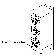
Figure 5
Blower Assembly - Rear View
5. Install the blower assembly:
a. Lead the power cord through the opening.
Allow it to collect inside the cabinet for the moment.
b. Place the blower assembly in the opening in the cabinet sheet metal.
Tilt the unit and insert the bottom of the blower through the opening so
that retainer features at the bottom of the blower assembly engage the
sheet metal at the bottom of the opening. See Figure 6.
c. Secure the blower assembly to the cabinet.
Tilt the unit up flush against the cabinet.
d. Install four screws, two at the top and two at the bottom and tighten.
Note -
The blower assembly may encounter mechanical interference from a
screw securing the plate holding the cabinet key switch. If this occurs, remove
the screw causing the interference, secure the blower to the cabinet using all
four screws, then reinstall the screw in the key switch plate.
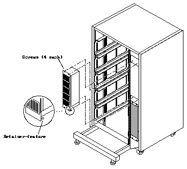
Figure 6
Installing the Blower Assembly in the Expansion Cabinet
6. Secure the power cord inside the cabinet.
Dress the power cord down the inside of the rack to the vicinity of the AC
power sequencer and secure it using tie wraps. Roll any excess cord and
tuck it into the space under the power sequencer and secure using tie wraps.
7. Plug in the blower assembly.
Plug the power cord into the rear of the power sequencer. Use the switched
outlet identified in Figure 7.

Figure 7
Plugging the Blower Assembly into the Power Sequencer
Replacing the Rear Screen Panel
1. Insert the panel so the bottom flange engages behind the top of the kick
panel.
2. Tilt the panel flush against the frame and secure using two screws.
Replacing the Side Panel
1. Place the side panel against the cabinet so the inner lip of the panel
engages tabs at the top of the cabinet.
2. Lower the panel bottom so it is flush against the cabinet.
3. Fasten the two captive screws at the bottom of the panel.
Begin with a safety inspection.
-
Ensure that the AC power switch on the expansion cabinet rear is off.
-
Verify that the power cord is plugged into the correct facilities power outlet
The cabinet in question may be installed in a mission-critical environment
requiring a complete and thorough power on process to be performed. For this
reason, it is beyond the scope of this manual to provide comprehensive power
on procedure that can cover all possible system installations.
Power on the cabinet using the correct power on procedures found in the
service manual and/or the system administration guide for the system that
you are working on.