Chapter 1 Netra 150 Server Product Note
This document contains the late-breaking news for the Netra 150 server.
Proper Ordering of Bay Disk Drives
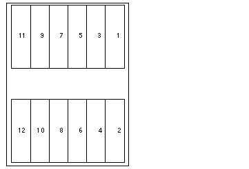
In the Netra 150 Server Service Manual , the instructions for installing a bay disk drive say to install the disks from top-to-bottom, left-to-right. These instructions are incorrect; the drives should be installed from top-to-bottom, right-to-left. Refer to Figure 1-1 for the proper ordering of the drives.
Figure 1-1 Proper Ordering for Bay Disk Drives

Product Information
You can find all the available product information and late-breaking news for the Netra 150 server by accessing the following web site:
http://netra.sun.com
Booting a Netra 150 Server with a Configuration Diskette
Whenever you boot your Netra 150 server, it will look for the configuration information for your site in one of two places:
-
If you have a diskette with your configuration information inserted in the Netra 150 server diskette drive, the server will automatically boot using the configuration information stored on that diskette.
-
If you do not have a diskette inserted in the Netra 150 server diskette drive, the server will boot using the configuration information stored on the Netra 150 server system hard drive instead.
When you boot your Netra 150 server, you should remove the configuration diskette from the diskette drive so that the system will boot using the configuration information stored on the system hard drive. However, if you want to boot your system using the configuration diskette, you must verify that the diskette has the most up-to-date configuration information stored on it or your system will boot using out-of-date configuration information.
Time Taken for New Disk to Sync
It takes approximately one hour for a new disk to sync if there has been a disk failure.
Devices Can Only be Connected to Serial Port A on the Netra 150 Server
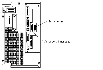
You can only connect devices to serial port A on the Netra 150 server; do not connect any devices to serial port B on the server. Refer to Figure 1-2 for the location of serial ports A and B on the Netra 150 server.
Figure 1-2 Location of the Serial Ports on the Netra 150 Server

Powering Off the Netra 150 Server
If you shut down the Netra 150 server using the Netra HTML interface (found under System Administration:Restart and Shutdown), this does not remove power from the Netra 150 server. To completely power off the server, the power switch located on the back of the Netra 150 server must be used. This is the switch for the server. Turning this switch to the off position will actually turn off the power to the server.
Note -
This switch is only to be used to power off the server to allow new hardware to be installed or replaced. Always shutdown the server gracefully before powering off the server.
Performing a Cold Boot Causes Inherent Delays
A cold boot (powering up the system) on a server with 12 disks takes about 5 minutes to boot up. This is because there are inherent delays in powering up each of the disk drives sequentially. This situation should not be misinterpreted as problems with booting.
Installing a Netra 150 Server in a Generic (Non-Sun) Cabinet
It may be possible for you to install a Netra 150 server in a cabinet that you bought from a company other than Sun Microsystems as long as the cabinet is between 30" and 36" in depth. You can use the instructions given in the Model 150 Server Series Rack-Ready Installation Manual (802-6742-10) to install a Netra 150 server in a non-Sun cabinet as long as you keep the following things in mind:
-
The Netra 150 server takes up six rack units in a cabinet.
-
The instructions in the sections Powering Off the Expansion Cabinet and Internal Access (pages 2-1 through 2-5) apply to Sun cabinets only; refer to the manual that you received with your generic cabinet for instructions on powering off your cabinet and removing the outer panels.
-
The instructions in steps 17 and 18 on page 2-11 apply to Sun cabinets only. When you get to this point in the instructions, substitute steps 17 and 18 with these steps:
-
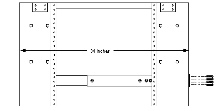
Measure the distance between the side rails on your rack.
Figure 1-3 shows the distance measured between the two side rails on a Sun rack, which is 34 inches. Keep in mind that you want to measure from the outer part of the side rails.
Figure 1-3 Positioning the Bracket Assembly in the Rack

-
Slip the long bracket over the end of the short bracket/slide assembly, with the lip on the short bracket/slide assembly facing out (Figure 1-4).
Figure 1-4 Mounting the Long Bracket on the Short Bracket/Slide Assembly

-
Measure the distance between the lip on the long bracket and the end of the short bracket/slide assembly and extend the two brackets until the distance between the ends of the two brackets equals the distance between the side rails on your rack.
-
Flip the assembly over and extend the runner as out as far as possible, then use as many nuts and bolts as possible to loosely secure the long bracket to the short bracket/slide assembly.
You should be able to use 2 to 5 nuts and bolts to loosely secure the brackets together, depending on the distance between the ends of the two brackets. Do not tighten the nuts and bolts at this time.
-
The instructions in the sections Cabling the Model 150 Server, Restoring the Expansion Cabinet and Powering On the Expansion Cabinet (pages 2-16 through 2-22) apply to Sun cabinets only; refer to the manual that you received with your generic cabinet for instructions on cabling, replacing the outer panels and powering on your cabinet.
- © 2010, Oracle Corporation and/or its affiliates
