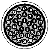
A P P E N D I X  A
A

SCSI Array Specifications

This appendix provides the specifications for the Sun StorEdge 3120 SCSI array. The topics covered are:


A.1 Summary of Physical Specifications

TABLE A-1 Sun StorEdge 3120 SCSI Array Physical Specifications

Feature

Description

Height

1U (1.75 inch / 4.445 cm.)

Width

19 inch / 48.26 cm. (body)

Depth

Main chassis 18 inch/ 45.72 cm.


To back of power supply:

20 inch/ 50.8 cm.


To back of power supply handle:
21 inch / 53.34 cm.

Weight (JBOD)

30 lbs. / 13.608 kg. with 146 GB drives

General

  • 4 hot-pluggable drives in a 1U (1.75 inch high) chassis
  • Ultra 320 SCSI buses
  • Autosensing AC or DC power supplies

Density

  • Up to 584GB in a SCSI array
  • 21-inch chassis depth

Reliability

  • Redundant hot swappable FRUs
  • N+1 hot swappable power and cooling
  • NEBS Level 3 and HALT test certified; Designed to meet 99.999% reliability


Note - Add 10.6 lbs. (4.8 kg.) for packaging if you want to know the shipping weight of your array.


A.2 Summary of Sun StorEdge 3120 SCSI Array Specifications

Feature

Description

General

  • 4 hot-pluggable drives in a 1U (1.75 inch high) chassis
  • Ultra 320 SCSI buses
  • Autosensing AC or DC power supplies

Density

  • Up to 584GB in a RAID array
  • 21-inch chassis depth

Reliability

  • Redundant hot swappable FRUs
  • N+1 hot swappable power and cooling
  • NEBS Level 3 and HALT test certified; Designed to meet 99.999% reliability

Array System
Storage Resource Management

  • Four Ultra320 SCSI channels
  • Support for Sun StorEdge Configuration Service and Sun StorEdge Diagnostic Reporter management software


A.3 Agency Approvals and Standards

Product Safety

Country

Standard

U.S.

UL Listed to UL60950:2000, 3rd Edition

Canada

CSA Standard CAN/CSA-C22.2 No. 60950-00 3rd Edition

Germany

TÜV

European Union

EN60950:2000

Japan

Part of World-wide CB Scheme

Australia

Part of World-wide CB Scheme

Argentina

Resolution 92-98 (S-Mark)

Germany

GS mark (ergonomics) (Rheinland)

Russia

Part of World-wide CB Scheme (GOST-R mark)

Russia

Hygienic Mark-(ergonomics)

Electromagnetic Compatibility

Country

Standard

U.S.

FCC #47, Part 15, Subpart B, Class B

Canada

ICES-003

Japan

VCCI Class B

European Union

EN 55022:1998 Class B

Australia/New Zealand

AS/NZS 3548:1996

Taiwan

BSMI CNS 13438 Class B

Russia

GOST-R mark

Germany

Same as European Union

Argentina

S mark

Electromagnetic Interference

Test

Standard

Harmonics Emissions

EN 61000-3-2:2000 (No Limits)

Voltage Flicker

EN 61000-3-3:1995/A1:2001 (No Limits)

ESD

EN 55024 (8kV Contact, 15kV Air)

RF Field

EN 55024 (10V/m)

Electrical Fast Transient Burst

EN 55024 (1kV I/O, 2kV Power)

Surge

EN 55024 (1kV I/O, 1kV Power L-L, 2kV Power L-G)

RF Conducted

EN 55024 (3V I/O and Power)

Power Frequency Magnetic Field

EN 55024 (N/A monitors only)

Voltage Dip and Interruption

EN 55024 (0V/0.5cycle, 70%V/0.5sec, 0V/5sec)


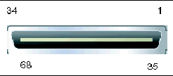
A.4 SCSI Host or Drive Connector

 FIGURE A-1 SCSI Host or Drive Connector

Figure showing the pinouts for the SCSI Connector

Figure showing the pinouts for the SCSI Connector

Figure showing the pinouts for the SCSI Connector
TABLE A-2 SCSI Connector Pin Descriptions

Pin

Description

Pin

Description

1

Data 12 +

35

Data 12 -

2

Data 13 +

36

Data 13 -

3

Data 14 +

37

Data 14 -

4

Data 15 +

38

Data 15 -

5

Parity 1 +

39

Parity 1 -

6

Data 0 +

40

Data 0 -

7

Data 1 +

41

Data 1 -

8

Data 2 +

42

Data 2 -

9

Data 3 +

43

Data 3 -

10

Data 4 +

44

Data 4 -

11

Data 5 +

45

Data 5 -

12

Data 6 +

46

Data 6 -

13

Data 7 +

47

Data 7 -

14

Parity 0 +

48

Parity 0 -

15

Ground

49

Ground

16

DIFF_SENS

50

Ground

17

TERM_PWR

51

TERM_PWR

18

TERM_PWR

52

TERM_PWR

19

N/C

53

N/C

20

Ground

54

Ground

21

ATN +

55

ATN -

22

Ground

56

Ground

23

BSY +

57

BSY -

24

ACK +

58

ACK -

25

RST +

59

RST -

26

MSG +

60

MSG -

27

SEL +

61

SEL -

28

C/D +

62

C/D -

29

REQ +

63

REQ -

30

I/O +

64

I/O -

31

Data 8 +

65

Data 8 -

32

Data 9 +

66

Data 9 -

33

Data 10 +

67

Data 10 -

34

Data 11 +

68

Data 11 -


A.5 SCSI Host or Drive Cable

Standard .8mm 68-pin LVD SCSI cable:

 FIGURE A-2 Cross-section of the 68-Conductor SCSI Pinout for LVD/MSE SCSI

Figure showing the 68-Conductor SCSI Pinout for LVD/MSE SCSI.
TABLE A-3 SCSI Connector Pin Numbers and Cable Pairs

PIN# CABLE SE/LVD
PAIR

PIN# CABLE SE/LVD
PAIR

1 30SR/+DB12

2 31SR/+DB13

3 32SR/+DB14

4 33SR/+DB15

5 34SR/+DBP1

6 16SR/+DB0

7 17SR/+DB1

8 18SR/+DB2

9 19SR/+DB3

10 20SR/+DB4

11 21SR/+DB5

12 22SR/+DB6

13 23SR/+DB7

14 24SR/+P_CRCA

15 25GND/GND

16 15DIFFSENSE

17 14TPWR/TPWR

18 13TPWR/TPWR

19 12RSVD/RSVD

20 5GND/GND

21 6SR/+ATN

22 7GND/GND

23 4SR/+BSY

24 3SR/+ACK

25 8SR/+RST

26 9SR/+MSG

27 10SR/+SEL

28 2SR/+C/D

29 1SR/+REQ

30 11SR/+I/0

31 26SR/+DB8

32 27SR/+DB9

33 28SR/+DB10

34 29SR/+DB11

35 30-DB12/-DB12

36 31-DB13/-DB13

37 32-DB14/-DB14

38 33-DB15/-DB15

39 34-DBP1/-DBP1

40 16-DB0/-DB0

41 17-DB1/-DB1

42 18-DB2/-DB2

43 19-DB3/-DB3

44 20-DB4/-DB4

45 21-DB5/-DB5

46 22-DB6/-DB6

47 23-DB7/-DB7

48 24-DBP/-P_CRCA

49 25GND/GND

50 15GND/GND

51 14TPWR/TPWR

52 13TPWR/TPWR

53 12RSVD/RSVD

54 5GND/GND

55 6-ATN/-ATN

56 7GND/GND

57 4-BSY/-BSY

58 3-ACK/-ACK

59 8-RST/-RST

60 9-MSG/-MSG

61 10-SEL/-SEL

62 2-C/D/-C/D

63 1-REQ/-REQ

64 11-I/O/-I/O

65 26-DB8/-DB8

66 27-DB9/-DB9

67 28-DB10/-DB10

68 29-DB11/-DB11


*SR=Signal Return, *RSVD=Reserved, *GND=Ground, *TPWR=TERMPWR