| C H A P T E R 5 |
|
Software Management Tools |
This chapter describes the software management tools used for monitoring and managing the Sun StorEdge 3120 SCSI array. Topics include the following:
|
Note - For other supported software, see the Release s for your array. |
This section describes the software management tools available for monitoring and managing the Sun StorEdge 3120 SCSI array with in-band connections.
The following software management tools are provided on the Sun StorEdge 3000 Family Professional Storage Manager CD, provided with your array. The Sun StorEdge 3000 Family Documentation CD provides the related user guides.
For details on how to install Sun StorEdge Configuration Service, Sun StorEdge Diagnostic Reporter, or the Sun StorEdge CLI software, refer to the Sun StorEdge 3000 Family Software Installation Manual.
Sun StorEdge Configuration Service supports standalone JBOD arrays. However, because the Sun StorEdge 3120 SCSI array does not have a RAID controller or RAID controller firmware to manage the disks, this software support is limited to enabling JBOD support and viewing component and alarm characteristics.
See Viewing Component and Alarm Characteristics.
Use JBOD support only when you have a SCSI array connected directly to a host. This enables you to monitor peripheral device condition and events.
To monitor peripheral device condition and events for a JBOD device from the Sun StorEdge Configuration Service Console, you first need to enable JBOD support.
1. Select View  Agent Options Management.
The Agent Options Management window is displayed.
2. Select the Enable JBOD Support check box.
3. To immediately display the JBOD in the main window, you need to probe for new inventory. Select View  View Server and click Probe.
The JBOD is displayed in the main window.
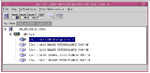
In a single-bus configuration, both ports of the JBOD array are connected to one HBA on the server, as shown in the following example.

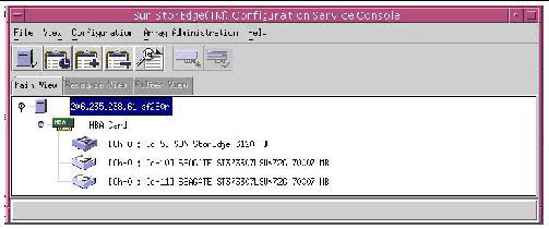
In a dual-bus configuration, each port is connected to its own HBA, as shown in the following example.

|
Note - In a dual-bus configuration, if each port is connected to different servers, the program can only monitor the JBOD from the server connected to port B. |
In Sun StorEdge Configuration Service, to view environmental component and alarm characteristics, use the View Enclosure window or, for some components, the main window.
You can also view environmental and drive components using the Sun StorEdge CLIL show enclosure-status command. For details, see show enclosure-status.
In the main window, device states are color-coded and symbol-coded so that it is easy to identify when a device is in a state that requires attention. The status is propagated along the device tree, enabling you to trace a failure down to the device level. See TABLE 5-1 for device status details.
To view the cause of a critical or degraded device status, review the event log. For details on the event log, refer to the Sun StorEdge 3000 Family Configuration Service User's Guide.
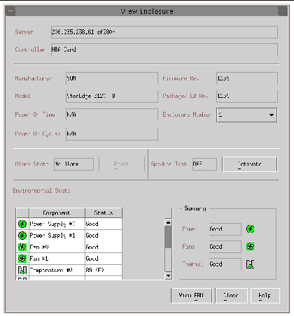
The View Enclosure window displays the component and alarm characteristics for a JBOD device. The window displays the status for environmental components including the fan, power supply, and temperature sensor.
To view the environmental component and alarm characteristics of a SCSI array from the Sun StorEdge Configuration Service Console, perform the following steps.
1. Select the EMU (SCSI) or SES (Fibre Channel) icon .
.
2. Choose View  View Enclosure.
To display FRU ID information, click View FRU.

Sun StorEdge Diagnostic Reporter supports standalone JBOD arrays. However, triggered event notification is limited to environmental and hard drive failures. Refer to the Sun StorEdge 3000 Family Diagnostic Reporter User's Guide for more information.
The Sun StorEdge CLI supports JBOD arrays. However, because JBOD arrays do not have a RAID controller or RAID controller firmware to manage the disks, this CLI support is limited to the following sccli commands:
The about command displays version and copyright information.
The following example shows the about text for the CLI:
sccli> about Sun StorEdge 3000 Family CLI Copyright 2002 Dot Hill Systems Corporation. All rights reserved. Use is subject to license terms. sccli version 1.5.0 built 2004.01.26.23.49 |
This command exits the interactive mode.
The help command displays a short synopsis of the available commands.
If no command is specified, basic usage information is displayed.
The quit command exits the interactive mode.
The select command selects a new device to which subsequent commands are issued. If no device is specified, and more than one choice exists, a menu of choices is displayed. This command should not be used on the command line because a select command is implicitly done if no device name is specified.
sccli> select c15t0d0 sccli: selected /dev/rdsk/c0t5d0s2 [SUN StorEdge 3310 SN#00028E] sccli> select 199.249.246.28 sccli: selecting se3000://199.249.246.28:58632[SUN StorEdge 3510 SN#000187] |
This command illuminates the LED in the enclosure adjacent to the specified disk (or slot). For JBODs, specify a disk device using a Solaris device name such as sd31 or c1t0d0s2, or specify a slot number. Use the show led-status command to show the status of the identified disk drive.
To illuminate a disk drive LED, use the following parameters:
In the following example, the LED adjacent to the drive with SCSI address 3 in the enclosure is set to on:
This command displays the array configuration including inquiry information, FRU information, and the enclosure status which includes the status for the fan, power supply, temperature sensor, and drive slots. The configuration can be displayed onscreen, or written to the specified file. The output is plain text by default, but XML output may be obtained by specifying the --xml option.
|
If the -x or --xml options are specified, XML output is generated. |
|
|
Specify the filename for the configuration file that you want to show. |
Enclosure status values include:
The following example writes the configuration information to the myconfig.xml file.
The following example shows a portion of the JBOD configuration.
The show enclosure-status command shows the status for all chassis components including SAF-TE information, fan, power supply, temperature sensor, and drive slot status.
|
Note - In dual-bus configurations, half the drives display a status of Absent. The drives are present, but because of a SAF-TE design limitation, the information does not display. |
Enclosure status values include:
Disk slots refer to the backplane FRU to which disks are connected.
|
Note - The Enclosure SCSI Channel Type values include single-bus and dual-bus. Throughout the documentation and the CLI, the term "split-bus" is interchangeable with the term "dual-bus." For details on configuring an array, see Connecting Sun StorEdge 3120 SCSI Arrays to Hosts. |
The following example shows the enclosure status for a Sun StorEdge 3120 SCSI device.
This command displays field-replaceable units (FRU) ID and status information. All FRU information is retrieved from the SAF-TE device.
|
One or more of the FRU components is exhibiting a fault condition. |
The following examples return all FRU information for the JBOD unit:
The following example shows a partial list of the FRUs in a Sun StorEdge 3120 SCSI device:
This command displays the status of the LED adjacent to the specified disk drive slot in the array enclosure or expansion chassis.
To show the status of LVD JBOD enclosures, use the following parameters:
The following example shows the status of the LED adjacent to the disk assigned to drive slot 3 for an expansion chassis:
This command displays information returned by the SAF-TE device embedded in SCSI LVD RAID enclosures or JBODs.
The output includes the serial number of the chassis in which it is installed, the vendor and product IDs and SAF-TE firmware revision, and the "SAF-TE firmware package" revision, which refers to firmware for other microprocesses in the chassis that are managed by the SAF-TE processor.
The following example shows the SAF-TE device information for a Sun StorEdge 3120 SCSI array.
sccli> show safte-devices Id Chassis Vendor Product ID Rev Package ------------------------------------------------------ 6 006498 SUN StorEdge 3120 D 1159 1159 |
The version command displays the version number of the CLI.
Use your standard host system disk management utilities for all disk management in a JBOD array, such as partitioning and formatting. Refer to your host system documentation for more information about disk management.
For maintenance and troubleshooting information, see Maintaining and Troubleshooting Your Array.
The Sun StorEdge 3120 SCSI array supports Veritas Dynamic Multi-Pathing (DMP) software.
|
Note - For other supported software, see the Release s for your array. |
To enable VERITAS Dynamic Multi-Pathing (DMP) support on VERITAS Volume Manager Version 3.2, ensure the HBA device SCSI initiator IDs are unique and then start the system. Perform the following steps.
1. Create a single-bus, multi-initiator configuration that links two cables to two different HBAs.
For details about creating a single-bus multi-initiator configuration, see A Single-Bus, Multi-Initiator JBOD Configuration.
2. Stop the server and at the ok prompt, type:
3. Issue the remaining commands on only one of the paths.
4. Edit or create the nvramrc to set the SCSI-initiator-id to a non-conflicting ID for these devices based on the information returned in step 2.
ok nvedit 0: probe-all install-console banner 1: cd /pci@6,4000/scsi@3 *** your path information here *** 2: 6 " scsi-initiator-id" integer-property 3: device-end 4: banner (Ctrl-c) |
6. Press Ctrl-c, and store the nvramrc by typing:
7. Set the system to use the nvramrc and reset auto-boot by typing:
8. Reset the configuration by typing:
9. Reboot the hosts. A system reboot is required to implement these changes.
Copyright © 2004, Sun Microsystems, Inc. All rights reserved.