| Oracle® VM User's Guide Release 3.0 for x86 Part Number E18549-03 |
|
|
PDF · Mobi · ePub |
| Oracle® VM User's Guide Release 3.0 for x86 Part Number E18549-03 |
|
|
PDF · Mobi · ePub |
Networking is a very broad concept with many different interpretations. Data center administrators typically have their own idea about what the best network configuration is in terms of performance, security and cost-effectiveness. In some cases physical network connections are readily available so bonding is preferred for failover or higher bandwidth, while other configurations use VLANs for network segregation or to compensate for the lack of free NICs. Some will use Ethernet connections for storage while others have dedicated fibre channel hardware at their disposal.
Generally speaking, data center operators tend to think essentially in terms of hardware: switches, routers, firewalls, cables, NICs (Network Interface Cards), and so on. The only widespread network virtualization concept to date is VLAN (Virtual LAN) technology. VLANs are also very frequently used in Oracle VM networking.
The networking infrastructure in the Oracle VM environment comprises connections between Oracle VM Servers, between Oracle VM Servers and Oracle VM Manager, between the Oracle VM Servers and their storage sub-systems, as well as communications among virtual machines deployed in the environment, and between virtual machines and external private or public networks.
These networking connections can leverage features supported by Oracle VM, such as networked file systems, clustering, redundancy and load balancing, bridging, and support for Virtual LANs (VLANs).
This chapter discusses creating and using Oracle VM networks, and contains:
When you create an Oracle VM network, you map available network ports to a set of logical Ethernet networks. You perform this mapping in Oracle VM Manager.
The physical network is the collection of physical connections in Oracle VM Manager and all Oracle VM Servers, and the switches and routers that allow information to reach its destination.
A logical network in Oracle VM is built on top of these physical connections. Each physical connection is called a network port. Other names for this physical connection include network interface card, or NIC, or network interface.
You define a name or alias for each logical network that you create. When you have created your networks, you connect the physical network ports to the logical networks.
Before you define the logical networks in Oracle VM Manager, you have to review the physical network configuration that you intend to use, such as VLAN and subnet usage. You also take into account the number of network ports, or NICs, available to your Oracle VM Servers. The minimum recommended number of ports required on a single Oracle VM Server is two, although one would suffice for test or demonstration purposes. If you have more than two ports on your Oracle VM Servers, you can design more redundancy or traffic isolation in your environment.
Oracle VM supports both 1Gbit and 10Gbit NICs. All network functions can either be on dedicated or shared physical networks, except for the virtual machine intra-server. For example, a physical network can be dedicated to Virtual Machine or Storage only, or can be dedicated for all network functions.
In Oracle VM a network can perform one or more network functions. Oracle VM has the following network functions:
Server Management: is used to manage the physical Oracle VM Servers in a server pool, for example, to update the Oracle VM Agent on the different Oracle VM Servers.
Note:
In Oracle VM the management network interface and the public interface (i.e. default route) are expected to be the same on each Oracle VM Server. Other types of network usage are allowed on the same interface, for example through the use of VLANs and/or network bridges.Live Migrate: is used to migrate virtual machines from one Oracle VM Server to another in a server pool, without changing the status of the virtual machine.
Cluster Heartbeat: is used to verify if the Oracle VM Servers in a clustered server pool are up and running. The heartbeat function has a network component, where a TCP/IP communication channel is created with each Oracle VM Server. Each Oracle VM Server sends regular keep-alive packets and these packets are used to determine if each Oracle VM Server is alive.
Note:
It is recommended to separate the cluster heartbeat function from networks with high load, such as storage and live migration networks. If bandwidth drops too low, heartbeating connectivity might be interrupted, which could lead to rebooting of virtual machines and Oracle VM Servers.Virtual Machine: is used for the network traffic between the different virtual machines in a server pool. The virtual machine role can be either standard Inter-Server (routable through standard switches), or Intra-Server (without a route to an external physical network and dedicated to the selected Oracle VM Server.).
Note that it is possible, and very likely, to have multiple networks with the Virtual Machine role in one Oracle VM Manager.
Storage: is used for all storage transport in a server pool. It is used by the Oracle VM Servers to connect to Ethernet-based storage repositories and server pool file systems. As with the Virtual Machine role, it is possible to have multiple networks with the Storage role.
The first step in configuring your Oracle VM environment is to discover your Oracle VM Servers. This step assumes that the Oracle VM Manager host and all of the Oracle VM Servers can communicate over the same network, though the Oracle VM Servers and Oracle VM Manager can reside in different subnets. When you discover the first Oracle VM Server, the management network is created automatically and takes its name from the subnet to which the Oracle VM Server is connected. Each additional Oracle VM Server discovered from the Oracle VM Manager either adds an entry into the existing management network or creates a new management network if the server is connected to a subnet where no Oracle VM Server was previously discovered. Each server in your Oracle VM environment can only have one interface designated for management, belonging to a single management network object in the Oracle VM Manager's database.
WARNING:
Although the Oracle VM Manager and its discovered and owned Oracle VM Servers may be on different subnets as long as they can reach each other, Network Address Translation (NAT) is not supported in this configuration. NAT would lead to a discrepancy between the actual management IP of the Oracle VM Server and the IP provided during discovery.
A network port on every Oracle VM Server is designated as the management interface during the installation of the Oracle VM Server and is configured as a bonded interface. You can add or remove ports in this bond, but you cannot change the bonding mode or remove the bond. Once a management network is created, it can only be deleted again if no servers have ports in the management network anymore.
After your management networks are in place, you plan for the creation of other types of network. Note that once a port is selected for a particular network, it cannot be selected again when creating additional networks. You can use a combination of network bonding and VLAN Groups to create all the networks needed for your environment, using your existing ports. Network bonding is covered in Section 6.3, "Building a Network Environment"; VLAN Groups are covered in Section 6.6, "VLAN Groups and VLAN Segments".
Figure 6-1 shows an example of an Oracle VM environment with split network functions. Each Oracle VM Server is connected to the management network, regardless of which server pool they belong to.
Each server pool has a separate network for heartbeating functionality and live migration. Since this type of network traffic occurs at the level of an individual server pool, the network does not need a gateway. Though you may create several networks for the heartbeating and live migration functions, a server can only belong to one network for each function.
As a rule, virtual machine (VM) traffic requires a dedicated network. In this example the VM network has a route to the internet (or corporate wide area network). You can create as many virtual machine networks as permitted by your network infrastructure.
The first two server pools are connected to a storage network with Ethernet based storage providers. Ethernet based storage is provided as either NFS file servers or iSCSI LUNs. Server Pool 3 has dedicated fibre channel storage, which requires a fibre channel switch and host bus adapters (HBAs) in all connected hardware components. Similar to networks for virtual machines, you create as many storage networks as needed to implement your storage strategy.
When you create a new network, you choose a network function and network elements to build this network. These network elements include network ports, bonds, or VLAN segments if VLANs are used in your environment. These network elements as well as the networks you create are stored as networking objects in the Oracle VM Manager database. Your Oracle VM Servers are unaware of these Oracle VM Manager network objects. Creating and managing network objects in Oracle VM Manager results in the configuration or deletion of the network devices (for example: ports, VLAN devices, bridges) present on Oracle VM Servers.
After reviewing your physical network environment and deciding on the logical distribution and grouping of these physical objects, you create the logical constructs in Oracle VM Manager to implement your network design. These logical constructs include:
Network bonds
VLAN groups
Networks
Bridges
Note:
Bridges are associated with networks. Network bridges are automatically created when creating networks for virtual machines.A short description of these objects and their usage is given below in the following sections:
If your network design includes interface bonding, you create these network bonds first. A bond is the aggregation of network ports – in Oracle VM a maximum of two – to provide redundancy and depending on the bonding mode, to increase performance. These bonds are often used in conjunction with VLANs, when traffic from several VLANs is allowed to use the same bond.
If your network environment comprises VLANs, your next step is to create VLAN Groups. With VLAN Groups, you determine which port or bond, on each Oracle VM Server, will accept traffic from more than one VLAN. Next, you specify the VLAN segments, as VLAN IDs, that are part of the VLAN Group.
Once these network building blocks are in place, you are ready to create networks using Oracle VM Manager. For each network, you must answer two questions:
What is the expected network function for your new network?
Network functions are discussed in Section 6.2, "Network Usage".
What are the building blocks for your new network?
These building blocks determine the network type in Oracle VM Manager. The choices when creating a network are:
Create a network with ports and bonds
Create a network with VLANs only
Create a network with ports and bonds, and VLANs
Create a logical network on a single server
If you create a network with ports, these ports, located on the Oracle VM Servers that will participate in the network, cannot be part of an already existing network.If you intend to use port bonding, create the bond(s) before creating your network. If you intend to allow traffic from several VLANs on a single port or bond, create the VLAN Groups before creating the network.
When creating a VLAN Group, you provide the following information:
The port or bond for each server participating in the network
The VLAN ID for each VLAN allowed to use the network
IP addressing is desired, the IP address to assign to each port or VLAN interface specified respectively in the bullet points above.
You can also create a network using a combination of VLAN interfaces, ports and bonds. If you choose this type of network, the bonds must be created first and the VLAN interfaces must already be part of an existing VLAN Group.
Finally, you can create a network which is intended for a single server. This type of network allows communication between the virtual machines running on a single Oracle VM Server, and does not allow external network traffic. A computing environment made up of several virtual machines, where the virtual machines provide services to each other over the network, could benefit from this type of network, without requiring additional network ports on the Oracle VM Server.
The next topics provide more information about network bonding, network bridges, VLAN Groups and VLAN segments. To create VLAN Groups, see Section 6.9, "Managing VLAN Groups". To create networks, see Section 6.10, "Managing Networks".
Network bonding refers to the combination of network interfaces on one host for redundancy and/or increased throughput. Redundancy is the key factor: we want to protect our virtualized environment from loss of service due to failure of a single physical link. This network bonding is the same as the Linux network bonding. Using network bonding in Oracle VM may require some switch configuration.
In Oracle VM, there are three modes of network bonding:
Active-Passive: there is one NIC active while another NIC is asleep. If the active NIC goes down, another NIC becomes active.
Link Aggregation: aggregated NICs act as one NIC which results in a higher throughput.
Load Balanced: the network traffic is equally balanced over the NICs of the machine.
During installation of Oracle VM Server, the network interface (selected when prompted for the management port) is configured as a bonded interface. The bond is created with only one interface. This is done because the reconfiguration of the management interface on the Oracle VM Servers is not supported. You can add a second interface to the already existing bond device without affecting the configuration of the original interface. This is illustrated in Figure 6-2, where a second network interface is added to bond0, the network bond created during installation. The bond interface now provides redundancy since the bonding mode is always set to active-passive for the management network.
Figure 6-2 also illustrates the configuration of a second bonded interface, bond1, which can be used for other network usage, such as the virtual machine function.
When creating a network with the virtual machine role, a bridge is created automatically on the port or bond added to the network for each Oracle VM Server participating in this network. All network packets generated by the virtual machines are sent to the bridge configured for the virtual machines' network. The bridge acts as a Layer 2 switch, and directs packets to other virtual machines running on the Oracle VM Server, or to the port or bond, if the packets' destination is outside of the Oracle VM Server.
Though each virtual machine deployed within a network is usually assigned an IP address, either static or assigned using DHCP, there is no need to configure an IP address for the bridge on the Oracle VM Servers. When configuring your Virtual Machine network, if you specify an IP address for the port or bond you selected for this network, it is assigned to the bridge. You can choose not to assign an IP address to the selected port or bond. In this case, the bridge does not acquire an address but still functions as a Layer 2 switch.
In Figure 6-3, two network ports are specified for the network with the virtual machine role. Therefore, these ports should be configured as a bonded interface. Since this network is configured with the virtual machine role, a bridge is automatically created on each Oracle VM Server in the network. Neither the bridge nor the ports in the virtual machine network, have IP addresses assigned to them, though you may assign IP addresses if you wish during network creation.
Bridges are only created for networks with the virtual machine role.
Oracle VM supports multiple virtual LANs, or VLANs, on the same network port or bond. Each VLAN is essentially an independent logical network operating with other VLANs over the same physical connection. This means that virtual machines deployed on different networks, connected through the same Oracle VM Server port (or bond), can have traffic directed to different VLANs. This feature is implemented using VLAN groups.
Configuring VLANs involves creating one or more VLAN Groups, each of which can house multiple VLANs. Each VLAN is assigned a distinct VLAN identification. The VLAN ID is used by an attached VLAN switch to segregate traffic among the different VLANs operating on the same link. When a VLAN is configured, it functions exactly like a separate physical connection.
You must configure the VLANs needed to support your network before you can use them. This is usually accomplished using switch trunking. Trunking involves configuring ports on the switch to allow multiple VLAN traffic on these ports, to ensure that packets are correctly transmitted to their final destination. Consult your switch vendor's documentation for information regarding trunking.
A VLAN Group is a logical grouping of VLANs, either tagged or untagged. If a VLAN is tagged, each packet transmitted to and from this VLAN contains a VLAN ID. Network traffic can contain a mix of tagged and untagged packets. If a packet does not contain a VLAN tag, the packet is destined to an untagged VLAN.
You create a VLAN group to direct the traffic from several VLANs onto a single port or bond on each Oracle VM Server in the server pool. For example, if a port or bond is expected to carry traffic for VLAN with ID 2 and for VLAN with ID 3, you create a VLAN Group and specify the two VLANs, VLAN 2 and VLAN 3. These VLANs appear as VLAN segments in the VLAN Group. After creating the VLAN Group, you create a network and specify one of the VLAN segments present in the VLAN Group. Each packet transmitted from virtual machines on this network is tagged with the VLAN Id for the VLAN segment specified during network creation. If you specify untagged during network creation, the packets can still flow through the port or bond defined in the VLAN groups, but the packets are untagged. The Ethernet switch, to which the Oracle VM Servers are connected, is responsible to transmit the packets to the appropriate VLAN, tagged or untagged.
Figure 6-4 illustrates the case of two virtual machine networks, whose network traffic flows through the same bonded interface.
Figure 6-4 Networks with VLANs and VLAN Group
The VLAN Group needed to support the configuration shown in Figure 6-4 contains two VLANs, with ID 2 and 3. The VLAN Group also contains two ports for each Oracle VM Server in the network. On each server, the ports are configured as a bond device. Once the VLAN Group is created, two virtual machine networks are added: the first network specifies the VLAN segment with ID 2 and the second network specifies the VLAN segment with ID 3, where both segments are defined in the VLAN Group. For each network, a bridge is defined for the specified VLAN segment, without an IP address since none is specified during configuration. Network packets from virtual machines deployed on VLAN segment 2 travel through the bridge and acquire a tag which identifies the packets as belonging to VLAN 2. Similarly, the packets issued from the virtual machines deployed on the network for VLAN segment 3 are tagged for VLAN3 with ID 3. The packets from both networks use either path to the switch if the bond is configured as active-active. The receiving ports on the Ethernet switch are configured using trunking or similar program to recognize network traffic for the two VLANs in the configuration. As such, the trunk ports will direct the packets to the correct VLAN on the switch, or other connected switches.
Depending on the number of available network ports on your Oracle VM Servers, and whether or not you use VLANs, you can create additional networks and assign network functions to them. The exception would be the Management function, which is already assigned, and cannot be removed from the management network(s) created when the Oracle VM Servers were discovered. For example, if your Oracle VM Servers have two NICs, you create a second network with the Virtual Machine role. If your storage is connected to the Management network, you can add the Storage role to your Management network if your storage is connected to the same network as defined by the Management network.
If you have more than two ports on your Oracle VM Servers, or if you are using VLANs, you can create additional networks with the Storage role. These networks connect your Oracle VM Servers to either iSCSI or NFS-based storage. Generally, all Oracle VM Servers that belong to the same pool access the same storage. For each network created, you select a port, bond or VLAN interface on each Oracle VM Server to participate in this network.
You can also create a separate network for the Live Migrate function. After the initial server discovery, the Live Migrate role is assigned to the Management network. Oracle VM encrypts migration traffic using SSL, to protect sensitive data from exploitation and to eliminate the requirement for a dedicated network. Nonetheless, if you have sufficient network resources on your Oracle VM Servers within a server pool, you can choose to create a separate network for live migration.
Similarly, the Cluster Heartbeat network function is assigned to the Management network upon discovering the first Oracle VM Server. The heartbeat communication does not generate a lot of traffic on the network, and therefore does not have much impact on the Management network. It is however susceptible to latency. For this reason, you can choose to create a separate network for the cluster heartbeat function.
Note:
Though you can create several networks for the heartbeat and live migration functions, each Oracle VM Server can only participate in one heartbeat and live migration network.Network configuration is independent of your server pool configuration, but both entities must be taken into account when designing your overall networking infrastructure. Oracle VM Manager communicates with all Oracle VM Servers in the environment, using the management port, independent of how Oracle VM Servers are grouped to form server pools. Some network configuration in your environment might be dependent on the storage available to specific server pools. Virtual machines deployed from separate server pools might use the same external network. For this reason, it is best to plan your network design based on current network and storage setup as well as anticipated growth. Each server in a server pool should have identical network configuration.
The next sections of this chapter describe how to use Oracle VM Manager to translate the network structure of your Oracle VM environment into VLAN Groups and networks. If you expect to use bonding of network ports in your environment, create those first. If your environment contains VLANs, create the VLAN Groups to support your VLAN setup. You can then specify the VLAN segments contained in these VLAN Groups when creating your networks.
The management port on each Oracle VM Server is specified at installation time and is automatically configured as a bonded interface. You create additional bonds to add redundancy and if desired, load-balancing to your network environment. Once created, these bonds can be used as building blocks when buildings VLAN Groups or networks.
This section discusses managing bonded interfaces and contains:
Creating bond ports
Making changes to bond ports
Deleting bond ports
To create a bond port:
In the Hardware view, select the Hardware tab.
In the navigation pane, select the Oracle VM Server on which the bond port is to be created. If the server is already part of a server pool, it will be listed under Resources. Otherwise, find and select the server in the Unassigned Servers folder.
In the management pane, select the Ethernet Ports tab. Make sure that the the selected server's ports to be used for the bond port are not part of an existing bond, network or VLAN group. Verify that the ports are available.
In the management pane, select the Bonding tab. Click Create to start the Bond Port creation wizard.
In the right pane of the Create Bond Port window, select the ports to be part of the new bond.
You can also assign an IP address to this bond now, or wait to assign an IP address later, when using the bond to create VLAN Groups or networks. If you chose to assign an IP address now, select the Addressing type, and if applicable, the IP address and netmask.
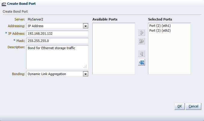
Optionally, add a description for this bond.
Except for the bond in the management network for each Oracle VM Server, you can specify the bonding mode from the Bonding list. See Section 6.4, "Network Bonding", for more information regarding network bonding modes.
Click OK to complete the operation.
Once you have created the bond port, you can make changes to its configuration. You can update its bonding mode, and add or remove ports as well as changing its description and IP addressing.
To update a bond port:
In the Hardware view, select the Hardware tab.
In the navigation pane, browse the tree structure and select the Oracle VM Server on which the bond port is to be updated.
In the management pane, select the Bonding tab.
From the list of bond ports for the server, select the bond port to update.
You can set or change the IP addressing, the description, or the ports that are part of the bond.
Click OK to save and apply your changes.
If the bond port is no longer in use in any VLAN Group or network, it can be deleted.
To delete a bond port:
In the Hardware view, select the Hardware tab.
In the navigation pane, browse the tree structure and select the Oracle VM Server on which the bond port is to be deleted.
In the management pane, select the Bonding tab.
From the list of bond ports for the server, select the bond port to delete.
Click Delete to delete the bond port.
Oracle VM supports multiple virtual LANs (VLANs) on the same NIC port. Each VLAN is essentially an independent logical network operating with other VLANs over the same physical connection. Using VLANs in an ideal way to minimize the number of required physical connections and NICs while concurrently separating traffic.Configuring networks to support VLAN traffic involves creating one or more VLAN Groups, each of which can house multiple VLANs. Each VLAN is assigned a distinct VLAN identification. The VLAN ID is used by an attached VLAN switch to segregate traffic among the different VLANs operating on the same link. When a VLAN is configured, it functions exactly like a separate physical connection.
VLANs need to be configured in the physical switches before you can use them. See Section 6.6, "VLAN Groups and VLAN Segments" for more information about using VLANs in your networking environment.
This section discusses using VLAN groups and contains:
To create a VLAN Group:
In the Hardware view, select the Hardware tab.
In the navigation pane, select Resources. In the management pane, select the VLAN Groups tab.
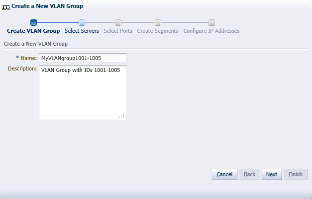
Click Create to start the VLAN Group creation wizard.
Enter a name in the Name field, and optionally a description in the Description field for the VLAN group and click Next.
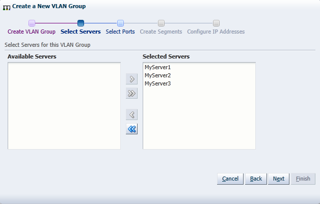
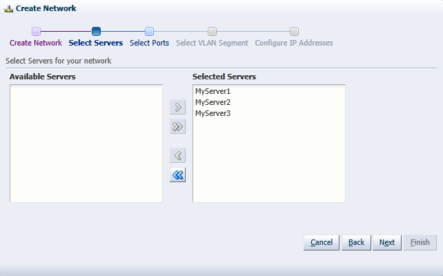
Select the Oracle VM Servers that have ports or bonds for this VLAN group and click Next.
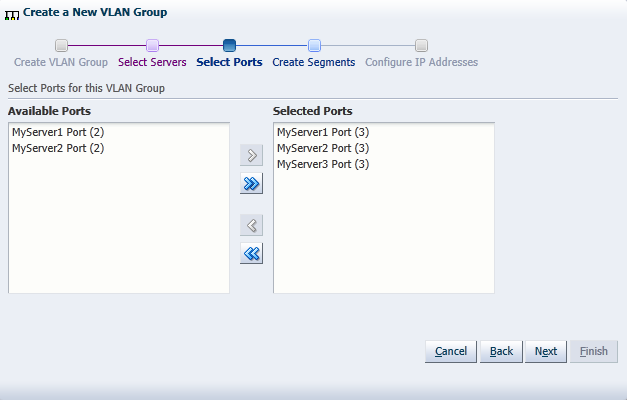
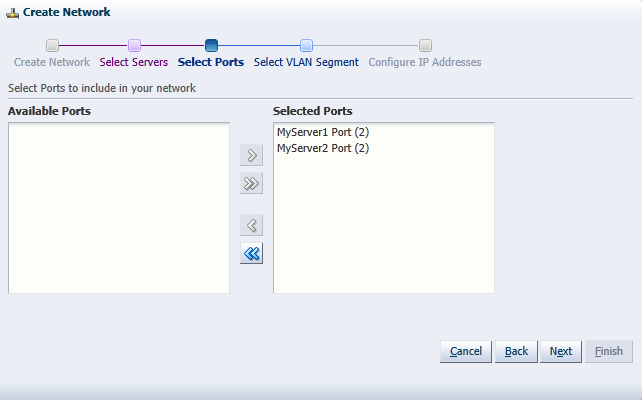
Select the port or bond of each Oracle VM Server that belongs to the network and click Next. The number between brackets next to the name of the Oracle VM Server corresponds with the NIC of the Oracle VM Server.
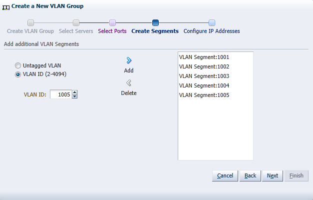
Add all VLAN Ids which belong to the VLAN group, and optionally select Untagged VLAN. Each selected VLAN ID appears as a separate VLAN segment in the VLAN Group.
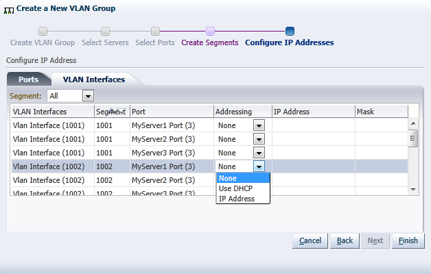
In the next screen, you can set IP addressing to either the ports and bonds or to the VLAN interfaces that are part of this new VLAN Group. Generally, you do not specify IP addresses to VLAN interfaces that are part of a network for virtual machines.
Click Finish to complete the operation.
To edit a VLAN Group:
In the Hardware view, select the Hardware tab.
In the navigation pane, select Resources. In the management pane, select the VLAN Groups tab.
From the list of VLAN Groups, select the VLAN Group you want to update and click the Update icon. The screens in the wizard are identical to the ones displayed in Section 6.9.1, "Creating a VLAN Group".
In the Edit VLAN Group screen you can change the name in the Name field, and the description in the Description field. Click Next.
In the Select Servers screen, you can add or remove Oracle VM Servers participating in this VLAN group. Click Next.
In the Select Ports screen, you can add or remove ports or bonds for the Oracle VM Servers in this VLAN Group. The number between brackets next to the name of the Oracle VM Server corresponds with the port of the Oracle VM Server. Click Next.
In the Edit Segments screen, you can add or remove VLAN IDs from the VLAN Group and optionally select Untagged VLAN. Each selected VLAN ID appears as a separate VLAN segment in the VLAN Group. It is possible to combine VLAN Ids with Untagged VLANs, so, first select the proper VLAN IDs, and then select Untagged VLAN.
In the Configure IP Address screen, you can update information for the ports or bond ports and for the VLAN interfaces that are currently part of the VLAN Group.
Select the Ports tab to modify the IP addressing of ports or bond ports that are part of the VLAN Group. You can update the IP addressing type, the IP address if selecting a static address, and the netmask. If the VLAN Group contains bond ports, you can also modify the bonding mode for the bond ports.
Select the VLAN Interfaces tab to modify the IP addressing of the VLAN interfaces that are part of the VLAN Group. You can update the IP addressing type, the IP address if selecting a static address, and the netmask.
Click Finish to complete the update.
You can only delete a VLAN Group if none of the VLAN segments in the VLAN Group are currently being used by a network.
To delete a VLAN Group:
In the Hardware view, select the Hardware tab.
In the navigation pane, select Resources. In the management pane, select the VLAN Groups tab.
Select a VLAN Group in the table, and click Delete.
Click OK to confirm the deletion of the VLAN Group.
The VLAN Group is deleted.
The initial Oracle VM Server installation configures the bare minimum network configuration. This allows Oracle VM Servers to set up their networking sufficiently to establish communication with Oracle VM Manager.
User created network devices (VLAN or a bond) on an Oracle VM Server are discovered by Oracle VM Manager, but these network devices are not associated with logical networks.
The management network, created during the Oracle VM installation, has the following network functions:
Server Management
Live Migrate
Cluster Heartbeat
When an Oracle VM Server is discovered, the port on which the Oracle VM Manager discovers the Oracle VM Server is added to this management network, and the port is configured as a bonded interface. See Section 6.4, "Network Bonding" for details about network bonding. You can add a port to this bond, and you can add or remove network functions for this network other than the management role. Other changes are not permitted. You can make the allowed changes to the configuration of the management network at any time using Oracle VM Manager. See Section 6.11, "Editing Network Data" for details about changing a network configuration in Oracle VM Manager.
Note:
In Oracle VM the management network interface and the public interface (i.e. default route) are expected to be the same on each Oracle VM Server. Other types of network usage are allowed on the same interface, for example through the use of VLANs and/or network bridges.Additional network configuration beyond what is done through the discovery process must be done using Oracle VM Manager.
All network configurations are persistent on the Oracle VM Servers to allow HA to work without requiring Oracle VM Manager. This includes enough logical information to allow the configuration to be recreated on Oracle VM Manager in the event that the Oracle VM Manager database is lost. All network configuration is also persistent on Oracle VM Manager.
When you build a new network, you use ports, bond ports or VLAN interfaces as building blocks for the network. For more information on network building blocks, see Section 6.3, "Building a Network Environment". You must also select the network usage for your new network. For a discussion of network functions and rules associated with them, consult Section 6.7, "Creating Additional Networks".
This section discusses managing networks and contains:
To create a network:
In the Hardware view, go to the Hardware tab, and select the Resources folder.
Select the Networks tab in the management pane.
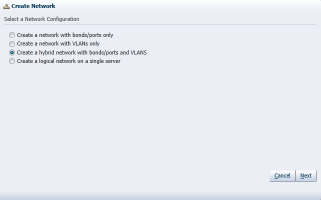
Click Create to start the Network Configuration wizard. The wizard offers the following choices:
Create a network with bonds/ports only
Create a network with VLANs only
Create a hybrid network with bonds/ports and VLANs
Create a logical network on a single server
Select the type of network to create, based on your network infrastructure.
If you have created bonds previously, you can now use them to create a network.
If you select to create a network with VLANs only, you must have created a VLAN Group previously. See Section 6.8, "Managing Bonded Interfaces" for details on how to create a VLAN Group.
You can also choose to create a network with a combination of bonds and ports, and VLANs.
The last selection, to create a logical network on a single server, creates an intra-server on a single Oracle VM Server. See Section 6.3, "Building a Network Environment" for information about intra-server networks. To create a logical network on a single server, proceed with step 7. For all other network types, continue with step 5.
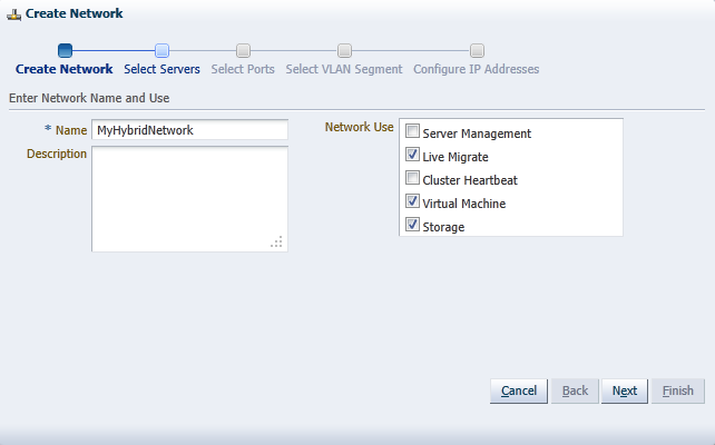
Enter the following network information:
Name: A name for the network.
Description: A description of the network. This is an optional field.
Network Usage: Select one or more network functions:
Server Management
Live Migrate
Cluster Heartbeat
Virtual Machine
Storage
See Section 6.2, "Network Usage" for more information regarding network functions.
Depending on the network type you selected to create, fill out the applicable screens in the wizard as described below:
Select Servers screen
(applies to network type: bonds/ports, hybrid – skip for type VLAN only)
Add the servers participating in this network. Click Next.
Select Ports screen
(applies to network type: bonds/ports, hybrid – skip for type VLAN only)
Select the ports or bonds of each Oracle VM Server that participates in this network. The number between brackets next to the name of the Oracle VM Server corresponds with the NIC of the Oracle VM Server. Click Next.
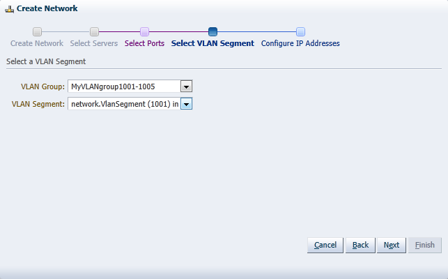
Select VLAN Segment screen
(applies to network type: VLAN only, hybrid – skip for type bonds/ports)
Select the VLAN Group from the list, then select the VLAN segment from the list. All VLAN Groups are available for selection, but VLAN segments already in use do not appear in the drop-down list. Click Next.
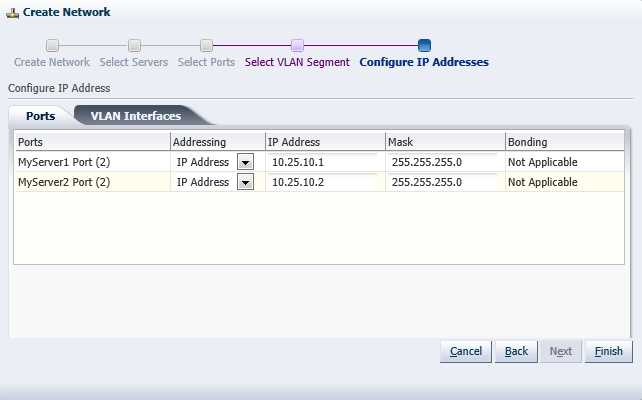
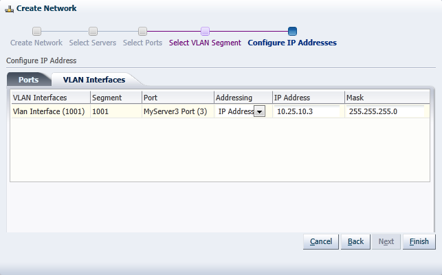
Configure IP Addresses screen – Ports tab
(applies to network type: bonds/ports, hybrid – select other tab for VLAN only)
Set the IP configuration for each port or bond. If you use static IP addresses, set the IP address, netmask and gateway. If you select DHCP, you still need to setup a DHCP server in your Oracle VM environment, since Oracle VM does not act as a DHCP server.
If your network has the virtual machine function, you do not have to define the IP data, which is required for all other network functions. See Section 6.5, "Network Bridges" for details on creating bridges for virtual machine networks.
If bonding is active, select the Bonding mode. See Section 6.4, "Network Bonding" for a description of the bonding modes.
Note: You cannot change the bonding mode for Management networks.
If you are creating a hybrid type network, select the VLAN Interfaces tab. If you are creating a network with bonds and ports only, click Finish to close the wizard and complete the network creation.
Configure IP Addresses screen – VLAN Interfaces tab
(applies to network type: VLAN only, hybrid – skip for type bonds/ports)
The VLAN interface selected for each port is listed, along with the IP addressing information. If IP information was supplied when creating the VLAN Group, this IP information is displayed. If no IP information was supplied when creating the VLAN Group, none is displayed.
If the network you are creating contains the virtual machine network function only, you cannot change the IP information from the VLAN Interfaces tab. If the network you are creating contains any other network function, alone, or combined with the virtual machine network function, you can edit the IP information from the VLAN Interfaces tab.
Click Finish to close the wizard and complete the network creation.
If you are creating a logical network for a single Oracle VM Server:
In the Create Network screen, enter a name and optional description for the new network.
In the Select Server screen, choose the server from the drop-down list.
Note:
The virtual machines deployed on a logical network for a single server, also called an intra-server network, are only accessible through their console if no other network is available.Click Finish to complete the network creation.
The following applies to all types of network except logical networks on a single server (intra-server networks).
To edit a network:
In the Hardware view, go to the Hardware tab, and select the Resources folder.
Select the Networks tab in the management pane, select Networks and click Edit... to start the Edit Network wizard.
Edit the network information and configuration as follows:
Name: Change the name of the network.
Description: Add or change a description for the network. This is an optional field.
Network Usage: Select or deselect one or more network functions:
Server Management
Live Migrate
Cluster Heartbeat
Virtual Machine
Storage
See Section 6.2, "Network Usage" for more information regarding network functions.
Depending on the network type you selected to edit, make changes in the applicable screens as described below. The screens in the wizard are identical to the ones displayed in Section 6.10.1, "Creating a Network".
Select Servers screen
(applies to network type: bonds/ports, hybrid – skip for type VLAN only)
Select or deselect the servers participating in this network. Click Next.
Select Ports screen
(applies to network type: bonds/ports, hybrid – skip for type VLAN only)
Select or deselect the ports or bonds of each Oracle VM Server that participates in this network. The number between brackets next to the name of the Oracle VM Server corresponds with the NIC of the Oracle VM Server. Click Next.
Select VLAN Segment screen
(applies to network type: VLAN only, hybrid – skip for type bonds/ports)
Select the VLAN Group from the list, then select the VLAN segment from the list. All VLAN Groups are available for selection, but VLAN segments already in use do not appear in the drop-down list. Click Next.
Configure IP Addresses screen – Ports tab
(applies to network type: bonds/ports, hybrid – select other tab for VLAN only)
Set or update the IP configuration for each port or bond. If you use static IP addresses, set the IP address, netmask and gateway. If you select DHCP, you still need to setup a DHCP server in your Oracle VM environment, since Oracle VM does not act as a DHCP server.
If your network has the virtual machine function, you do not have to define the IP data, which is required for all other network functions. See Section 6.5, "Network Bridges" for details on creating bridges for virtual machine networks.
If bonding is active, select the Bonding mode. See Section 6.4, "Network Bonding" for a description of the bonding modes.
Note: You cannot change the bonding mode for Management networks.
If you are editing a hybrid type network, select the VLAN Interfaces tab. If you are editing a network with bonds and ports only, skip the second tab and proceed to step 5.
Configure IP Addresses screen – VLAN Interfaces tab
(applies to network type: VLAN only, hybrid – skip for type bonds/ports)
The VLAN interface selected for each port is listed, along with the IP addressing information. If IP information was supplied when creating the VLAN Group, this IP information is displayed. If no IP information was supplied when creating the VLAN Group, none is displayed.
If the network you are creating contains the virtual machine network function only, you cannot change the IP information from the VLAN Interfaces tab. If the network you are creating contains any other network function, alone, or combined with the virtual machine network function, you can edit the IP information from the VLAN Interfaces tab.
After verifying or making the necessary changes to the network, click Finish to complete the network updates.
It may occur that a logical network becomes obsolete in Oracle VM. To keep your Oracle VM environment clean, it is recommended to remove all obsolete data, such as obsolete networks.
Note:
You cannot remove a virtual machine network if there are running virtual machines using the network.To delete a network:
In the Hardware view, go to the Hardware tab, and select the Resources folder.
Select the Networks tab in the management pane, select the network in the table and click Delete.
On the Delete Confirmation dialog box, click OK to delete the network.
The network is deleted.
To edit networking data, for example adding or removing network functions or updating port definitions, VLAN IDs, and so on, you use the Edit button in the respective management panes (Networks and VLAN Groups).
To go to the Networks and VLAN Groups management pane:
Select the Hardware view in the Navigation Tree.
Select the Hardware tab, and select Resources.
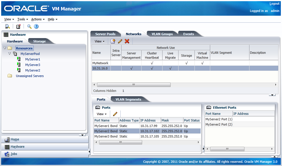
Select the Networks or VLAN Groups tab to view the respective management panes.
Editing a network or VLAN group launches the same wizard as creating networks or VLAN Groups. Update the data in the respective steps of the wizards.
In addition, you can modify most networking configuration data outside these wizards by going into the detailed tabs of the management panes instead of editing the top level network resources step by step.
The table below describes some specific actions to take when editing network ports and bonds. You can update the IP address of ports, and add, remove, and delete bond ports in a network. The following table describes the methods to use for each type of network update.
| Function | Method |
|---|---|
| Update IP information for ports | From the Hardware view, select the server which owns the port under Resources or under Unassigned Servers. Click the Ethernet Ports tab and select the port you wish to update. Click Edit to update the IP information.
Note: You can remove Ethernet ports. |
| Update bond information | From the Hardware view, select the server which owns the bond under Resources or under Unassigned Servers. Click on the Bonding tab and select the bond you wish to update. Click Edit to update the bond. You can update the IP information for the bond, the ports which are part of the bond and the bonding mode. With this release of Oracle VM, you can only have two ports in a bond.
Note: Do not change the bonding mode for the bond in the Management network. |
| Add a bond | From the Hardware view, select the server for which you want to create a bond. Click on Bonding tab and click Create to create the bond. You provide the IP information for the bond, the ports which are part of the bond and the bonding mode. |
| Delete a bond | From the Hardware view, select the server for which you want to delete a bond. Click on Bonding tab, select the bond and click Delete to remove the bond |
Similarly, network objects related to VLAN groups can also be updated through the detailed tabs of the applicable management pane. If you select a VLAN group in the VLAN Groups tab, you can:
select the Ports tab and edit details of a port related to this VLAN group
select the VLAN Segments tab and remove VLAN IDs or simply verify which networks are using the VLANs in this group
You can only view the VLAN interfaces on the VLAN segment. To edit the address information, for example, you must edit the VLAN group and set a static IP or DHCP in the last step of the wizard.
|
Copyright © 2011, Oracle and/or its affiliates. All rights reserved. Legal Notices |
|