| Oracle® Enterprise Data Quality for Product Data Application Studio Reference Guide Release 5.6.2 Part Number E23601-03 |
|
|
View PDF |
| Oracle® Enterprise Data Quality for Product Data Application Studio Reference Guide Release 5.6.2 Part Number E23601-03 |
|
|
View PDF |
This chapter explains how to create and use a transformation map in your DSA.
Transformation (or Transform) Maps operate in terms of data lenses, existing databases, web services, a collection of control operations on these knowledge repositories, string operations, and mathematical operations.
Base control flow of Application Studio is from left to right, input to output, and top to bottom. Top to bottom control typically relates to the equivalent of the "if-then" control structure in a programming language. In other words, if the top transformation fails based on the quality metric value, then control moves to the next lower data lens or other transformation.
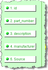
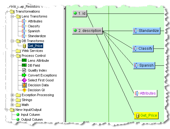
In the following example, the data lens using the DSA that contains this map classifies an item based on a description:
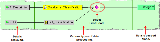
A database can also classify the same item based on its ID. The Select First Good decision uses the data lens classification over the database classification if they are both good because it is the top most transformation.
The Transformation Map possibilities are endless and are solely dependent on your input data and how you want to view and use the final output data. This chapter describes how to use the Transformation Map Builder to design your maps.
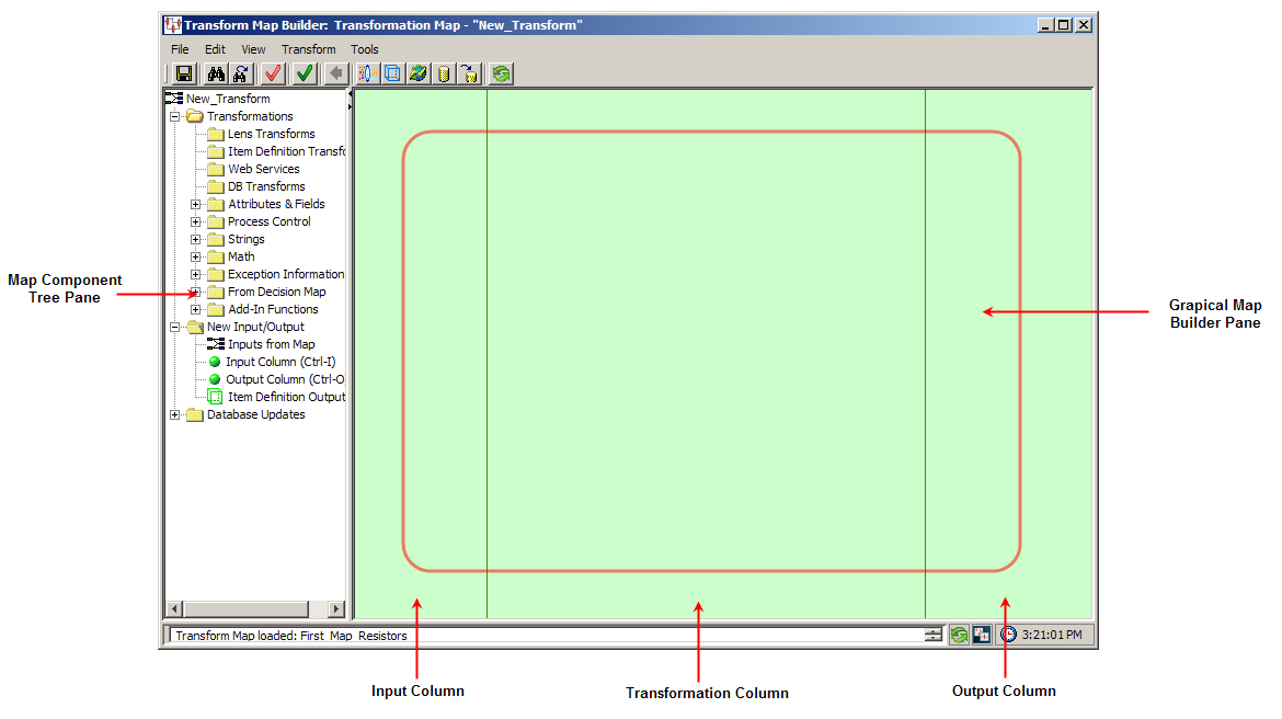
The Transformation Map client workspace is divided into two panes as follows:
This section describes the following Transformation Map client workspace functionality:
Transformation Map Menu and Toolbar Explained
Map Component Tree Task Pane
Graphical Map Builder Task Pane
The client workspace Frame Functionality is described on page 6.
The Transformation Map menus and toolbar are the alternate client workspace. The following briefly describes the DSA toolbar buttons from left to right:
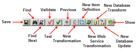
Many of the Transformation Map menus options and toolbar buttons behave the same way though on a transformation map rather than a DSA. For example, the Save command saves the open transformation map not the open DSA.
Tip:
The tooltips appear when you rest your mouse pointer on a menu item, button, tab, icon, or similar content.The following section briefly describes only the Transformation Map menu commands and corresponding buttons that are in addition to the DSA commands while all others are described in the DSA Menu and Toolbar Explained section on page 8:
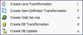
| Find…
Allows you to specify a search string (regular expression) and attempts to find it in your map. The text in the map that matches your search string is selected and highlighted in yellow Find Next Repeats the last search defined by a Find operation. Edit Map Description Allows you to edit the description for the open map. Create Lens Transformation |
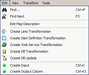 |
| Adds a data lens transformation to the map. Once a lens transformation is created, it appears in the Map Component Tree under the Lens Transform folder | |
| Create Item Definition Transformation
Adds an Item Definition transformation to the Map. Once the Item Definition transformation is created, it appears in the Map Component Tree under the Item Definitions Transformation folder. |
|
| Create Web Service Transformation
Adds a Web services call to the transformation map. |
|
| Create DB Transformation
Adds a database transformation to the map. Once a database base transformation is created, it appears in the Map Component Tree under the DB Transform folder. |
|
| Create DB Update
Adds a Database update to the transformation map |
|
| Create Input
Adds a new input node in the input column. |
|
| Create Output Column
Adds a new output node in the output column. |
|
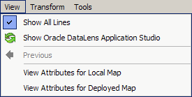
| Previous
Allows you to return to the parent or main Decision Map when you have navigated away from it. |
 |
| Test Map
Allows you to perform a quick test of the map with a single test line of data. For more information, see "Testing and Validating Transformation Maps". Validate DB Transformation Fields |
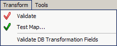 |
| Allows you to validate the database field's match what is being returned from the SQL query. For more information, see "Testing and Validating Transformation Maps". | |
| Map Options
Allows you to set options for the open map. For more information, see "Map Options". Options |
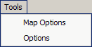 |
| Allows you to set options for global use in the Transformation Map workspace. For more information, see "Map Options". | |
The following table contains keyboard shortcuts that can help make the Transformation Map client workspace easier to use:
| Function | Shortcut Key |
|---|---|
| Save | Ctrl-S |
| Find | Ctrl-F |
| Find Next | F3 |
| Create Input | Ctrl-I |
| Create Output | Ctrl-O |
In addition, there may be single letter shortcuts that appear on context-sensitive menus that you can use to invoke the option quickly.
The Map Component Tree pane contains all of the components necessary to building a transformation or decision map and is used like the DSA Component Tree pane. These components are categorized into the hierarchical tree structure with the main folder indicting the name of the current map. These components are described in Transformation Map Builder Creation Components.
The Graphical Map Builder pane is a vertically ruled task pane divided into three building columns: input, transform, and output. These building columns represent the end-to-end transformation process.
You can use the Graphical Map Builder pane context-sensitive menu by right-clicking anywhere in this pane and use the options as follows.
| Show All Lines
Works as a toggle and when selected, all of the connecting lines between inputs, transformations, and outputs in the Graphical DSA/Map Builder pane are active. When this option is not selected, only the connecting lines for the selected node are active. Save Image |
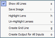 |
| Allows you to save an image of the Transformation Map as a JPEG file.
Highlight Lens Colorizes (or highlights) each transformation node that specifies a data lens or lens group to use the output of the transformation. You select the data lens that you are interested in for highlighting from the list of specified data lenses. It is not necessary to use the Un-Highlight Lenses option before repeating the use of the highlight, though you may not discern a change if the newly selected data lens also uses the transformation because it will already be highlighted. |
|
| Un-Highlight Lenses
Removes the highlighting from the nodes that became colorized with the Highlight Lens option. |
|
| Create/Delete Grid Line
Creates a yellow vertical grid line where the insertion point was resting when you right-clicked. This menu option changes to Delete Grid Line when you hover over a grid line that you have created so that it can be removed. You can differentiate the lines you have created and can remove those that are created by the Application Studio by the color; only yellow lines can be removed not black lines. |
|
| Create Output for All Inputs
Creates an output column node for each input column node. For more information, see "Creating Output Nodes from Input Nodes". |
|
| Check Parameters
Allows you to view the input data and SQL parameter counts of database transformation nodes and identifies any mismatches of these values. Edit Column Allows you to change the display name and column id of the selected input column node. |
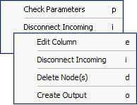 |
| Disconnect Incoming
Removes the connection between the selected node and any that precede it in the map. |
|
| Delete Node(s)
Removes one or more selected nodes from the map. You can use the Ctrl key to select more than one node out of sequence; use the Shift key to select nodes in a sequence. |
|
| Create Output
Creates an output column node for the selected input column node. |
|
| Create Outputs for Selected Inputs
Creates an output column node for each of the selected input column nodes. You can select multiple nodes as previously described. This option is active when several input column nodes are selected. For more information, see "Creating Output Nodes from Input Nodes". |
|
The creation of a Transformation Map depends on the existence of a processing step (core or alternative) in the calling DSA as in the following:
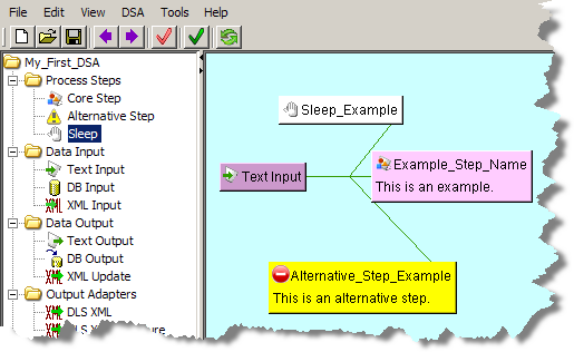
For more information, see "Processing Steps Folder".
To define a Transformation Map for a step (or open subsequently open one), you must double-click a step icon in the Graphical DSA Builder pane.
The name of the Transformation Map defaults to the name assigned to the calling step and cannot be changed.
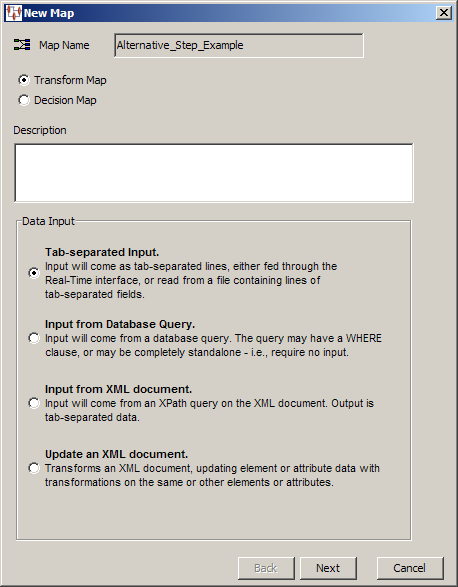
Use the New Map wizard as follows:
Select the type of map that you want to create using one of the options.
Enter a description for the new Transformation Map.
Select one of the four types of data input you want to use for this map.
Click Next to continue.
The next step varies depending on the type of map that you have chosen. Selecting Tab-separated Input results in a Finish dialog so you can click Finish to complete the wizard or Back to modify your choices. The remaining three data input options are described in the following sections.
When you select the Input from Database Query data input type, you must create the database query within the New Map wizard.
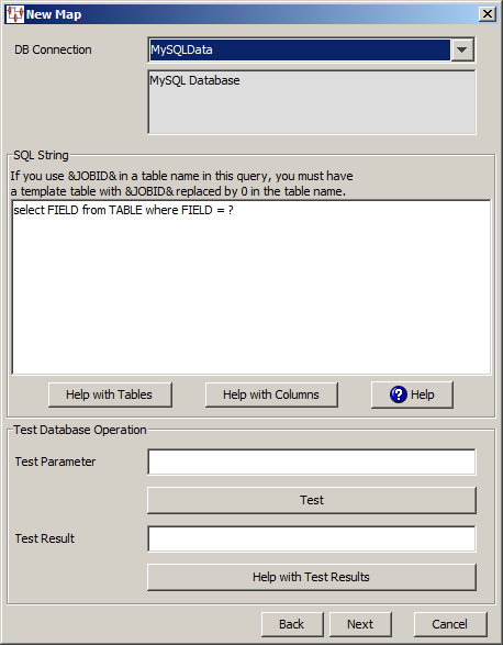
The New Map dialog box appears. Use this dialog box as follows:
You must select the type of database connection that you want to use. The list of database connections is populated based on those that you are configured in the Oracle DataLens Server. If the type of database connection is not listed, you must configure it in the Oracle DataLens Server so that it is available for selection when creating Transformation Maps.
Use the SQL String section to construct your database query with standard SQL query statements and syntax. For example, to determine if the inventory part numbers in your input data are an exact match to a standardized set of manufacturing part numbers you could use the following SQL statements:
SELECT 'Exact Match Mfg Std PN'||'|'|| inventory_item_id as match_type
FROM xyz_mfg_part_numbers_all_v
WHERE upper(mfg_part_num) = upper(&?3&)
AND upper(manufacturer_name) = upper(&?2&)
AND organization_id = &?1&
AND end_date is null;
This select clause must be compatible with your database. Optionally, you can use a question mark (?) in the select clause. At run-time, the question mark character is replaced with the transformation input data. This allows you to create a database transformation that varies with the content of the record being processed. Additionally, when database transforms are used to aggregate data fields from several different data sources, common access key information can be used across all data sources.
Use this button for assistance with the tables that are being used for the DB transformation.
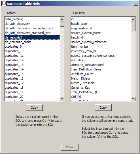
The Database Table Help dialog appears. You can select a table name in the Tables list and view the columns for that table in the Columns list. You can copy information from either list to paste into the SQL String field. One table can be copied in the Tables list; one or multiple columns can be selected in the Columns list. Click the appropriate Copy button for the information you want to copy to the clipboard and click Close. When you are returned to the Database Lookup Transformation dialog box, use Ctrl-V to insert the copied information into the SQL String field at the insertion point.
Use this button for assistance with the columns that are being used for the DB transformation.
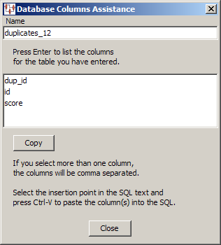
The Database Columns Assistance dialog appears. You can enter a table name in the Name field, click OK, and view the columns for that table. Then you can copy one or multiple columns names to the clipboard using the Copy button. Click Close to return to the Database Lookup Transformation dialog box and use Ctrl-V to insert the copied information into the SQL String field at the insertion point.
Select this button to view brief SQL query explanations and examples.
The Test Database section is provided to help you test the setup of the data source connection. You can test the data source definition by typing a data parameter value into the Test Parameter field and clicking the Test button. The test data value you entered is substituted for the question mark character(s) in the query string, and then the query is executed. The query results are displayed in the Test Result field.
When the query returns more than one record, the database transformation uses only the first record returned.
If there is an error in the connection definition, an information error message appears. Click the Help with Test Results button for help in interpreting error messages.
Note:
The following message indicates that the database connection tested good and is not an error message:Please check your database now
If an error message is received and there are no results in the Test Result field, the connection is good and the query is valid, but no matching results were returned.
When your input data is stored in an XML file, you should select the Input from XML Document option so that you can use XPath to retrieve the data.
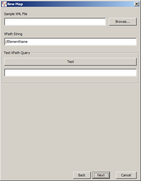
This allows you to locate and specify the XML file containing the input data. Then you enter an XPath expression to retrieve data from the specified XML file, which is then stored as tab-delimited output data.
You can test your XPath expression using the Test button; the results are displayed in the field below the button. For example, if your XML file contains 100 elements named description, you could select all of these elements with this expression:
//desc
Testing this expression would result in the following:
100 entries found
Tip:
Delete the contents of the test result field under the Test button to make it easier to differentiate between repeated testing attempts.You can use the Update an XML Document data input option when you want to update an existing XML file to update element or attribute data for transformations that use this same data.
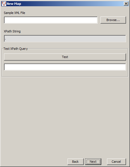
The functionality is the same as described in "XML Document Data Input" though you cannot specify the XPath expression, which is set to select the parent element thus selecting all elements. When you have selected the XML file and completed any testing, click Next to continue the wizard. To complete the new map, click Finish and the Transformation Map Builder opens.
All of the components (nodes and widgets) needed to design and maintain a transformation map are contained in the Map Component Tree pane and are described in this section.
The Transformations folder contains the nodes and widgets that are added to the Transformation Column to convert input data and ready it for output. The following sections describe each of these nodes and their associated functionality.
The following folders contain the Transformation Maps (by category) that you have created within the open DSA as follows:
Lens Transforms
Item Definition Transforms
Web Services
DB Transforms
This section describes the various attributes and field widgets that can be used in your Transformation Maps. For more information about using these controls in your map, see "Transforming Data Using Attributes and Fields".
Use with a defined lens transformation to extract the standardized data spanned by a phrase or term rule. The Lens Attribute widget uses one of the phrases or terms found in the selected data lens transformation.
The following is an example of the rules created in a data lens:
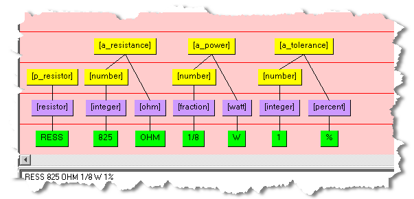
If a Lens Attribute is defined to extract text using the [a_resistance] phrase, then the resulting text is 825 OHM; no standardization is applied.
Use with a defined lens transformation that provides attributes to allow you to extract standardized data based on an Item Definition. The attributes are listed within their defined Item Definition for review and selection.
Use with a defined database transformation to allow you to incorporate several fields from the results of the database transformation query. The DB Field widget uses one of the fields found in the query of the selected database transformation.
Use with a defined lens transformation that provides classification information to allow you to define the Classification Code and Name and the Level of Classification to be used. Values can be Category and Level 1 - 5.
Use to retrieve the quality index from the transformation.
This section describes the various process control widgets that can be used in your Transformation Maps. For more information about using these controls in your map, see "Transforming Data Using Processing Controls".
Allows you to filter the results of a transformation based on a string match that you specify.
Allows you to select the first acceptable quality result, which is the first transformation result that meets or exceeds its quality indices, from several transformations. The data transformed by the selected transformation is passed on to the next step in the transformation process. This widget is only available in Transformation Maps.
Allows you to use numerical comparisons to identify the data to be output.
Allows you to employ the traditional 'If Then Else' conditional logic to direct data processing. This widget is only available in Transformation Maps.
Provides you with additional flexibility when dealing with record exceptions. Record exceptions occur when a record does not meet or exceed one or more of the transformation quality indices. The Convert Exceptions widget allows you ignore certain exceptions by setting a conversion text string. The default data output from this widget is an empty string.
Allows you to identify empty data records or database null values to force exception processing.
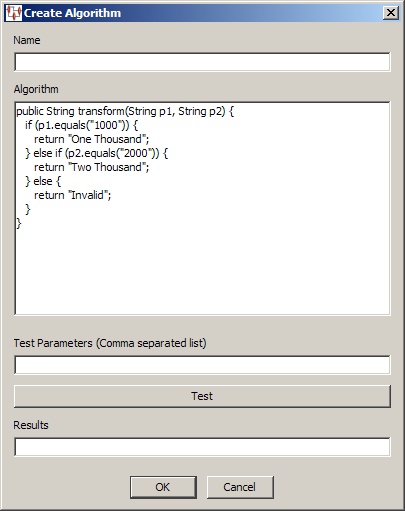
Allows you to process data using an algorithm that is Java-based processing, which you devise and enter. The algorithm can only include Java scripting employing the use of standard Java classes.
The Create Algorithm dialog box prompts you to enter a name for the widget and the algorithm. You can test the validity of your algorithm by entering testing parameters and clicking Test; the results appear in the Results field.
Allows you to run Windows or Linux system calls to use external processing in your Transformation Maps. This can be useful to use your custom scripts to process data that cannot be otherwise processed using the available transformation widgets. For example, you could run a shell script or command on Linux or a batch file or command on Windows.
The System Call dialog box prompts you to enter a name for the widget and a description of the process being called. You can select the check box to have the output that results from the system call returned or by default, the word Success is returned.
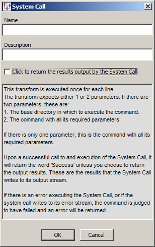
The parameters necessary for this node are the directory path of the system process you want to call and the command itself. These are provided using database input, literal string, text or other input nodes. Likewise, the Output nodes receive the results of the system call to be passed along in the processing.
This section describes the various string widgets that can be used in your Transformation Maps. For more information about using these controls in your map, see "Transforming Data Using String Operations".
Allows you to pass the data through the map without any changes.
Allows you to insert static text strings into your processing flow. This operator can be used to provide default text or labels for defined outputs.
Allows you to select a portion of an input string for processing. You select the starting position in the string, the number of characters to extract, and if any whitespace is automatically trimmed.
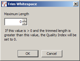
Allows you to trim leading and trailing spaces from the field it processes by selecting the Maximum Length the string will be after it is trimmed. If the data string is zero (0) and the maximum length is something other than zero then the Quality Index is set to zero.
Allows you to convert the case of the input into one of three different case control types: lower, upper, or proper.
Allows you to search for a string that you specify and replace it with the replacement string that you designate.
Allows you to search for strings that are empty (or null) or contain only spaces, and then replace it with the replacement string that you designate.
Allows you to compare string one with string two and can apply replacements for both the true and false results.
Allows you to use regular expressions to match and replace strings using standard Regular Expression syntax. Enter a name and the regular expression that you want to use. You can test the validity of your regular expression by entering the testing parameters and clicking Test; the results appear in the Results field
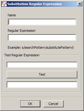
For more information, see "Regular Expressions".
Allows you to merge together two or more strings for further transformation. The strings are merged with a single space separating each input string
Allows you to extract the data in a specific field. Enter a name for the widget, the character that separates the input data fields, and select (or enter) the number of the field that contains the data to be extracted.
Allows you to prepare the input field to be split into two or more split fields; this widget is used in conjunction with the Split Field.
Use with the results of a Splitter widget to extract one or more characters intelligently respecting white space boundaries.
Allows you to build a regular expression to strip HTML tags or data and replace it with values you provide or a space.
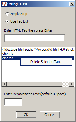
You can use a Simple Strip to replace anything between the less than (<) and greater than (>) symbols, or Use Tag List to provide the exact HTML tag you want to replace.
If you use the Use Tag List option, then you can enter a tag that you want to replace and press Enter. Repeat for each tag you want to replace. Selecting a tag in the list and right-clicking on it allows you to delete the tag from the replacement list.
Enter any replacement text or use the default replacement, which is a space.
An Ngram can be a single word (Unigram), two words (Bigram), or three words (Trigram). This widget allows you to output a pattern, unigram, bigram, trigram, RsIndex (the rsindex value is created with a Soundex algorithm to set a sounds like value), or to output dictionary status.
The valid pattern values are:
9 is used for numbersA is used for letters; uppercase A is always used not lowercase
All other characters, including special characters and spaces, remain unchanged.
When setting the dictionary status, the output values are:
1 means the pattern is in the dictionary0 (zero) means the pattern is not in the dictionary-1 means that no there is no dictionaryAll the arithmetic functions produce record exceptions if the input values are not appropriate for the function. Each can be set to a desired decimal precision in which to return the results. For more information, see "Transforming Data Using Math Operations".
This widget allows you to select one of four arithmetic operations: Add, Subtract, Multiple, or Divide two values. You can assign the number of decimal digits the results will be calculated to or accept the default of zero.
This widget allows you to select one of three rounding operations, Round Up, Round Down, or Round to Nearest. You can assign the number of decimal digits the results will be calculated to or accept the default of zero.
Allows you to select whether the data is set to the minimum or maximum of the numerical input value.
These widgets are used to receive information about exceptions from previous maps in the map flow. When used in a map, these widgets receive information about the Transformation Map that received the exception, the Transformation inside the map that received the exception, and the data lens involved in the Transformation (if any) that received the exception.
This widget receives the Transformation Map that created the exception upstream in the map flow.
This widget receives the name of the data lens, DB, Web service, or processing step inside the Transformation Map that created the exception received by this map.
Receives the name of the data lens inside the Exception Transform (if any) that created the exception received by the map.
These widgets pass results from a parent Decision Map to a child map. For more information, see "Decision Map Builder".
Passes decision data results. This eliminates the need to transform fields in the same record multiple times.
Passes data quality index results to the next widget. This allows for analysis of results from parent decisions maps so that you can identify why the decision was made.
Passes all of the Item Definition attribute information from a previous decision map. This allows attributes to be passed from one map to another and provides all attributes defined within an Item Definition.
These widgets provide specialized functions for your use.
Integrates an Oracle database with Enterprise DQ for Product. To activate this functionality you must contact Oracle Consulting Services.
Allows you to retrieve one specific field from an input data record. The widget that you connect the Get Field widget to must pass the specified string from a field. The field index, field separator, and default value are specified in the fixed parameters. Typically, this is used in a logic decision in a map.
The nodes in this folder vary depending on the type of map that you have selected, text, database, or XML. The following is a comprehensive list of all input nodes included in the Application Studio:
An input node is a placeholder that indicates that the input data is from another map.
An input column node is a placeholder that indicates the type of input data to be used for the map.
An output column node receives data from an input or transform node to pass to another DSA step.
An Item Definition node receives attribute data from an Item Definition transform node to pass to another DSA step.
A database field input node receives data from the fields in the input database to pass to transformation or output column nodes.
An input node that receives data from a field in an XML input data file.
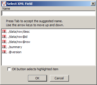
Enter a name for the node. As you type, the letters are matched against the XML Fields in the list. If a match is found, it is automatically selected and you can press Tab to accept the selection. If you click OK, your entry in the Name field is used unless the check box is selected, in which case the automatically selected XML Field is used rather than the text you entered.
Additionally, you can select the XML field containing the data using the arrow keys, and then press Tab to select that field.
An output column node that passes data from a transformation node to a field in an XML data file. The same Select XML Field dialog box is used as previously described.
These widgets enable you to find and match data records, or create an output table.
This widget is described in Advanced Mapping and DSA Concepts on page 153.
Note:
The matching capability, which includes the following database update widgets, is an additional Enterprise DQ for Product component that is purchased and licensed. If this widget is not activated (an error occurs with attempted use), this functionality may not be activated. For more information, see Oracle Enterprise Data Quality for Product Data Oracle DataLens Server Administration Guide. To purchase this additional component, contact Oracle Sales.These widgets are described in Advanced Mapping and DSA Concepts on page 153.
This widget is described in Advanced Mapping and DSA Concepts on page 153
This widget is described in Advanced Mapping and DSA Concepts on page 153.
These widgets are described in Advanced Mapping and DSA Concepts on page 153.
Define the input column by adding input nodes to the map to be connected to a transformation column node or an output column node. Input nodes are essentially placeholders that indicate the type of data input.
The nodes that appear in the New Input/Output folder of the Map Component Tree pane vary depending on the type of map input that you selected when creating the map as described in "Creating Transformation Maps".
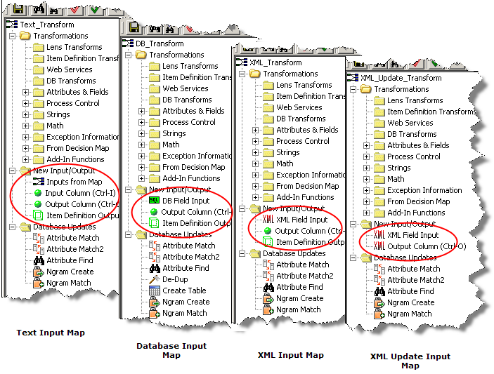
The Application Studio intuitively changes the types of nodes (input, output, and database update) needed for each map and only those nodes are available for ease of use.
You can add nodes to the input column of your map by double-clicking on the Input Column node in the Map Component Tree pane, or dragging a node and dropping it in the Graphical Map Builder pane, or by using Ctrl-I.
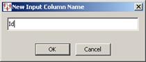
Enter a descriptive name for the node and click OK.
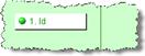
The new input node is now ready to be connected to a transformation node to supply data to it. The number of input nodes that you create is solely dependent on your input data though typically there are several input nodes to effectively process data.
Tip:
All unconnected nodes in Transformation Maps are colored white, connected nodes are green, and selected nodes are yellow.You can automatically create and connect output nodes for one or more input nodes.
To create an output node for a single input node, right-click on the input node, and then select Create Output.
The output node is created with the same name as the input node and the nodes are connected.
You can select multiple input nodes and then create output nodes using use the Shift (selecting continuously) or the Ctrl (selecting discontinuously) keys while selecting the nodes, right-clicking on one of them, and then selecting Create Outputs for Selected Inputs.
Output nodes are created for the selected input nodes appear and are logically connected to the input data.
The following sections explain how to define the nodes in the Transformation Column of your Transformation Maps.
Lens transformations are defined by the data lenses that have been created using the Knowledge Studio.
To create a Lens Transform, from the Edit menu, select Create Lens Transformation or use the button of the same name.
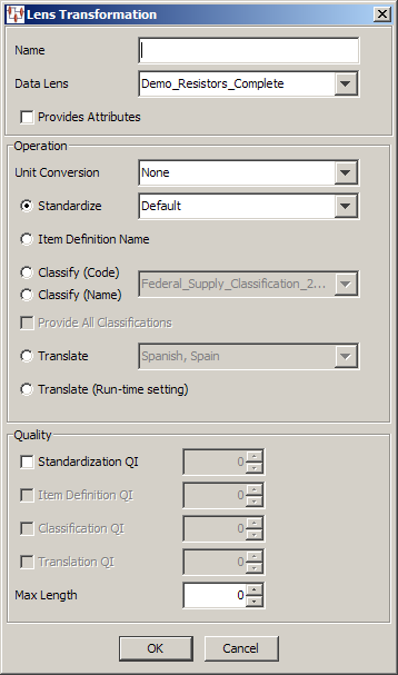
Complete the Lens Transformation dialog as follows:
Use this field to name your transformation. This name is displayed in the Map Component Tree pane and in the Graphical Map Builder pane.
Use this list to select the data lens to use for this transformation. This list of available data lenses is built from the data lenses selected into the Oracle DataLens Server.
Use this check box when the Lens transformation will be used to extract terms and phrases defined within the data lens. When this check box is selected, only dialog fields associated with standardization are enabled. Lens Attribute controls in the Process Control folder of the Map Component Tree pane only work with data lens transformations defined to provide attributes.
Select one of the following operations for this lens transform:
Use this list to transform the input data using the selected unit conversion. The list of available unit conversions is defined by the selected data lens project.
Select this option if the input data is to be standardized, and then select one of the available standardization types from the list. This list is populated by the standardization types contained in the selected data lens.
Select one of these options if the input data is to be classified, and then select one of the available classification types from the list. This list is populated by classification types contained in the selected data lens. For more information, see "Classification Outputs Tab".
Select this option if the input data is to be translated to a target locale, and then select the translation language. The list of available translation languages is populated by the selected data lens.
Select this option if the input data is to be translated to a target locale, and you want the target locale to be selected at run-time. This function allows you to use the same map to translate the input data set into multiple languages by selecting the target locale for each transformation job.
Modify this section as follows:
When this check box is selected, the value in the adjacent value field is used to control the quality of the output records. Records that meet or exceed the standardization quality index are routed to the output records. Records that do not meet the standardization quality index setting are routed to the exception records file. The Standardization QI can range from 0-100.
The Standardization QI is very valuable in determining the overall quality of the transformation result. Because of this, the Standardization QI is always available no matter what transformation operation is selected in the Operation section. The Standardization QI value encodes how much of the input text is recognized by the data lens. When the Standardization QI is very high, 80 to 100, the data lens used in the transformation recognizes most or all of the input data. When a data lens recognizes all of the input data, its transformation will be highly accurate. The Standardization QI is often used in conjunction with the other quality indices to ensure the highest possible quality results.
When this check box is selected, the value in the adjacent value field is used to control the quality of the output records. Records that meet or exceed the classification quality index are routed to the output records. Records that do not meet the classification quality index setting are routed to the exception records file. The Classification QI can range from 0-100.
These controls are only active if a translation operation is selected. When the Translation QI check box is selected, the value in the adjacent value field is used to control the quality of the output records. Records that meet or exceed the translation quality index are routed to the output records. Records that do not meet the translation quality index setting are routed to the exception records file. The Translation QI can range from 0-100.
This field is used to control the length of the transformation result. Records that are less than or equal to the Max Length value are routed to the output records. Records that are greater than the Max Length value are routed to the exception records file. A Max Length of zero (0) means that no length limitation applies.
Item Definitions provide the Item Definition name and attributes based on the Name, Text, Value, and Number for use with both the DB Update and Item Definition Output nodes.
To create an Item Definition Transform, from the Edit menu, select Create Lens Transformation or use the button of the same name.
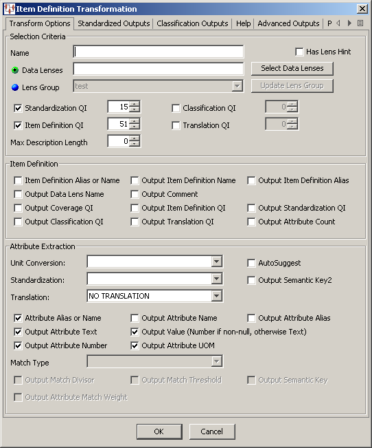
The Item Definition Transformation dialog box appears. To navigate the tabs, you can click the left and right Scroll Arrows at the right to scroll to the right or back to the left. In addition, you can click the Show Tab List button, as shown in following figure, to see a list of all tabs to select them individually:
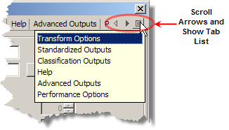
Use this dialog box as described in the following sections.
Modify this section as follows:
Enter a name for this transformation. This name is displayed in the Map Component Tree pane and in the Graphical Map Builder pane.
Select this check box to set the data lens that will be used first in the transformation. This feature optimizes the processing of data when your Lens Transformation has multiple data lenses or a Lens Group to use during processing by setting the data lens that is used first. This data lens is the one most likely to process the data successfully therefore the remaining data lenses do not have to be used for processing. The data lens that is first in the selected list of multiple data lenses (created using the Select Data Lens button) is set as the lens hint.
Enter the data lens to use for this transformation. To use multiple data lenses or a lens group, use the Select Data Lens button to select data lenses.
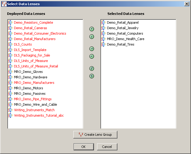
The Select Data Lenses dialog box appears. The list of available (deployed) data lenses is populated based on the data lenses deployed into the DataLens Administrator.
Data Lenses are moved between list boxes using the right and left arrows or by double-clicking on a data lens. The up and down arrows are used to change the data lens processing order. Any deployed data lenses that appear in red are not compatible with the selected data lens because the Unit Conversion, Standardization, or Match types are different.
If the Has Lens Hint check box is selected, the first data lens in the list of Selected Data Lenses is used first to process the data.
You can create a specific group of data lenses for use with all Item Definition transformations in your DSA instead of selecting them individually in each transform. A lens group can be used in one or multiple DSA steps and in multiple DSAs
Lens groups allow you to update the lens group in one transformation that automatically updates all other transformations using the lens group, which avoids the need for each Transformation Map throughout the DSA when you want to add or remove a data lens. This feature greatly increases consistency and reduces errors in DSAs.
To create an Item Definition transformation lens group:
Click the Select Data Lens button.
Add the first of the data lenses that you want to group to the Selected Data Lenses list.
Click OK to return to the Item Definition Transformation dialog box. This allows the Application Studio to determine the other data lens that are compatible with your selection.
Click Select Data Lens.
Add the remaining data lenses that you want to include in this lens group.
Click Create Lens Group.
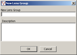
Enter a descriptive name for the new lens group and a description that indicates its purpose. Both of these fields must be completed.
Click OK. An informational message appears to alert you that the new lens group has been created.
The Oracle DataLens Server is updated to include this data lens. You can view and delete all lens groups from the Oracle DataLens Server though you must edit them in the Application Studio.
Click OK to return to the Item Definition Transformation dialog box.
The Lens Group field is updated to display the lens group that you just created though it is not active.
Click the Lens Group option to activate this field and the Update Lens Group button.
Note:
To use this lens group in other Item Definition transformations, you must edit each transformation and select it using the Lens Group controls.Select this option to activate the field and the Update Lens Group button. You can select one of the listed lens groups to use for this transformation. If there are no lens groups listed, you can create them as previously described.
Update Lens Group
You can edit your lens group by editing any one of the Item Definition transformations that use it. Updating a lens group in one transformation permeates throughout the DSA in one simple action.
Clicking the Update Lens Group button displays the Select Lenses for Lens Group: Lens Group Name dialog box. This dialog box operates identically to the Select Data Lenses dialog box previously described. You can add or remove data lenses to reconfigure the lens groups.
Note:
Lens groups can only be deleted using the Oracle DataLens Server. For more information, see Oracle Enterprise Data Quality for Product Data Oracle DataLens Server Administration Guide.When this check box is selected, the value in the adjacent value field is used to control the quality of the output records. Records that meet or exceed the standardization QI are routed to the output records. Records that do not meet the standardization quality index setting are routed to the exception records file. The Standardization QI range that can be defined is 0-100.
When this check box is selected, the value in the adjacent value field is used to control the quality of the output records. The Item Definition QI encodes how much of the input text is recognized by the data lens based on the Required and Scoring Attributes that have been defined within each of the Item Definition values. The range that can be defined is 0-100.
When this field is used, the transformation verifies that the Description Length, based on either the Non-Item Definition Standardized Description or the Item Definition Standardization Description, does not exceed the value defined in this field. The Maximum Description Length that can be defined is 0-500.
When this field is used, the transform provides an understanding about whether that record has been classified. The value is 100 if classified once or 100 divided by the number of classifications found. The range that can be defined is 0-100.
When this field is used, the transform provides an understanding of how many attributes have been translated correctly. The range that can be defined is 0-100.
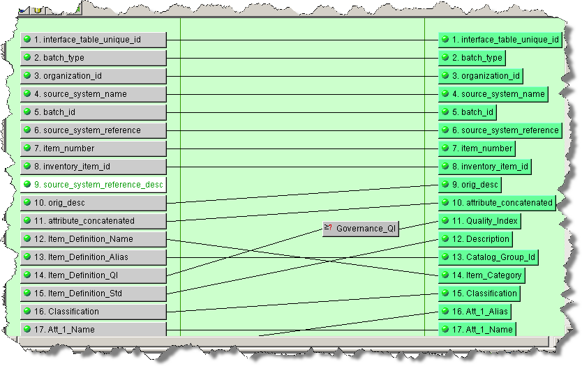
The following tables describe the Item Definition dialog box output check boxes and provide brief descriptions, the output column order, and the output name. The tables are in a top to bottom, then left to right order. The order is based on all of the outputs being selected. If there are fewer outputs selected then the order will be adjusted accordingly.
| Check box | Description | Output Column Order | Output Name |
|---|---|---|---|
| Item Definition Alias or Name | Select to output either the Item Definition Alias or Name. The Alias is output if present; otherwise, the Name is output. You can select this check box or the Output Data Lens Name check box not both. | 1 | Item_Definition_Name
|
| Output Data Lens Name | Select to output the data lens name. You can select this check box or the Item Definition Alias or Name check box not both. This option must be set to use the attribute search functionality provided by the Attribute Find control. | 2 | Lens_Name |
| Output Coverage QI | Select to output the Coverage QI, which is the percentage of non-white space characters that are recognized (covered) and placed into attribute in an Item Definition. This includes optional attributes. | 9 | Coverage_QI |
| Output Classification QI | Select to output the Classification QI. | 12 | Cls_QI |
| Output Item Definition Name | Select to output the Item Definition name. This option must be set to use the attribute search functionality provided by the Attribute Find control. | 1 | Item_Definition_Name |
| Output Comment | Select to output the Item Definition description. | 3 | Comment |
| Output Item Definition QI | Select to output the Item Definition QI; it must be at least 51. | 10 | Item_Definition_QI |
| Output Translation QI | Select to output the Translation QI. | 13 | Trn_QI |
| Output Item Definition Alias | Select to output the Item Definition alias. | 1 | Item_Definition_Alias |
| Output Standardization QI | Select to output the Standardization QI. | 11 | Std_QI |
| Output Attribute Count | Select to output the Attribute Count. | 4 | Attribute_Count |
| Control | Description | Output Column Order | Output Name |
|---|---|---|---|
| Unit Conversion | Select the appropriate Unit of Measure type for use with unit of measure conversions for standardized values for the attributes that are being transformed. | N/A | N/A |
| Standardization | Select the appropriate Standardization for the attributes that are being transformed. | N/A | N/A |
| Translation | Select the appropriate Translation for the attributes that are being transformed. | N/A | N/A |
| AutoSuggest | Select to output suggestions as an XML structure in the Attribute Text field where a suggestion is available. The output is generated in a format for use in the Governance Studio to display in AutoSuggest tabs. | 18 | Att_Number_Text |
| Output Semantic Key2 | Select to output the Semantic Key2. | 8 | Semantic_Key2 |
| Attribute Alias or Name | Select to output the Attribute Name. | 15 | Att_Number_Name |
| Output Attribute ID | Select to output the Attribute ID. | Att_Number_ID |
|
| Output Attribute Text | Select to output the Attribute text. | 18 | Att_Number_Text |
| Output Attribute Number | Select to output the Attribute number. | 19 | Att_Number_Number |
| Output Attribute Name | Select to output the Attribute name. | 15 | Att_Number_Name |
| Output Attribute Group ID | Select to output the Attribute Group ID. | Att_Number_Group_ID |
|
| Output Value (Number if non-null; otherwise Text) | Select to output the Attribute value. | 17 | Att_Number_Value |
| Output Attribute UOM | Select to output the Attribute Unit of Measure. | 20 | Att_Number_UOM |
| Output Attribute Alias | Select to output the Attribute alias. | 16 | Att_Number_Alias |
| The following matching controls are not active unless a Match Type has been defined in your data lens. | |||
| Match Type | Select the appropriate Match type for the attributes that are being transformed. | N/A | |
| Output Match Divisor | Select to output the Match Divisor. | 6 | Match_Divisor |
| Output Attribute Match Weight | Select to output the Match Weight. This option must be set to use the attribute matching functionality provided by the Attribute Match controls. | 21 | Att_Number_Weight |
| Output Match Threshold | Select to output the Match Threshold. This option must be set to use the attribute matching functionality provided by the Attribute Match controls. | 7 | Match_Threshold |
| Output Semantic Key | Select to output the Semantic Key. | 8 | Semantic_Key |
The Standardized Outputs tab is no longer actively used and will be deprecated in a future release. For further information, contact Oracle Consulting Services.
Use the Standardized Outputs tab as follows.
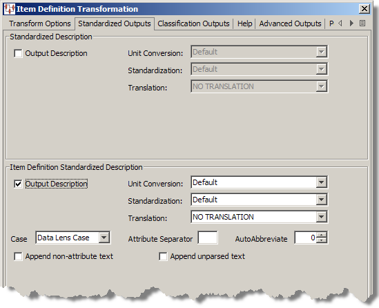
The Standardized Description section of this tab is no longer actively used and will be deprecated in a future release. For further information, contact Oracle Consulting Services.
| Control | Description | Output Column Order | Output Name |
|---|---|---|---|
| Output Description | Select to output the Item Definition Standard Description. | 13 | Item_Definition_Std |
The Output Description is based on the selection of the following controls:
Select the appropriate Unit of Measure type that should be used for unit of measure conversions for standardized values.
Select the appropriate Standardization type to be used for the Standardized Description.
Select the correct case to be used with the standardized description. You can select one of the following options: DataLens case, uppercase, lower case, or proper case. Setting a standard case in the transform overrides the case settings in a data lens.
DataLens case is the case that is defined within the data lens itself and can be viewed in the rewrite rule for the attribute in the Knowledge Studio on the Standardize Items tab, on the Standardize Attributes sub-tab.
Enter a character value when a separator is required between each of the attributes defined within the Order Attributes for each of the Item Definitions.
Enter a value for the number of characters to be shown in the standardized description. The Application Studio uses an algorithm to intelligently shorten the description to the desired length while maintaining readability. The following are not abbreviated:
Required attributes
Attributes containing numbers, such as units of measure, part numbers, and model numbers
Individual words that would be shorter than three characters if abbreviated
Select this check box when the standard description should include the defined attributes within the Item Definition and any other attributes that have been identified within the data lens.
Select this check box when the standard description should include the defined attributes within the Item Definition and all other unparsed text.
Note:
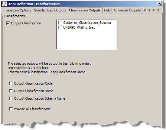
When selected, both of these appending options place the values at the end of the attributes defined within the Item Definitions for the specific Standardization Type selected.This tab is not active unless a Classification Type has been defined in your data lens.
You can classify data using multiple secondary classification schemas in one Lens Transform, which simplifies your DSAs.
Use the Classification Outputs tab as follows.
| Control | Description | Output Column Order | Output Name |
|---|---|---|---|
| Output Classification | Select this check box, and then the classification schemas you want to use to classify your data from the list. This list is populated by the Classification Types that are defined in the data lenses or Lens Group. | 14 | Classification |
The output is in a single output field that is vertical bar (|) delimited based on your selection of the check boxes. The following figure shows the types of classification information you can output:
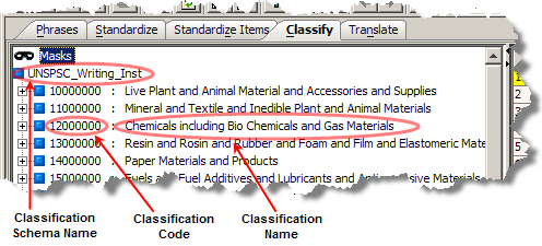
Select to include the code used to classify the input data.
Select to include the name of the classification code used to classify the input data.
Select to include the name of the selected classification schemas used to classify the input data.
Select this to include all of the preceding classifications.
It is not necessary to select any XML outputs on this tab as this data is automatically generated. The automatic generation of the XML outputs allows you to use the attribute search functionality provided by the Attribute Find control.
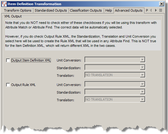
If you want to use this tab, it is recommended that you contact Oracle Consulting Services for assistance because this functionality is applicable only in special circumstances.
By clicking on this tab, and then clicking the Show Help button, you can view the order in which fields are output.
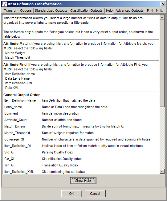
The information remains active until you close the Item Definition Transformation dialog. In other words, if you close the dialog and reopen it, you must click Show Help to activate the information for viewing.
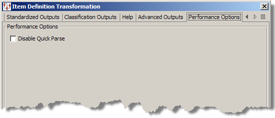
By default, the Quick Parse functionality is enabled. Quick Parse optimizes the parsing speed by parsing only the required attributes of all data lenses that are participating in the classification of the input data. This is applicable to both Lens Groups and when multiple data lenses are applied.
When your input data text contains no spaces or punctuation to aid parsing (conjoined), the possibility exists that some of the data may not be parsed because there are no logical text breaks so the Quick Parse function does not parse data preceding a match that could further classify the data. If your input data is conjoined, you should create an identical Lens Transform step with Quick Parse disabled that immediately follows the first to ensure that all data that was not parsed initially is parsed. You can still realize the parsing optimization even though there are two parsing steps in your DSA.
Select the Disable Quick Parse check box to stop the Application Studio from using Quick Parse.
The fields of data that you have configured to be output from an Item Definition transformation when your DSA is used to process input data are provided in the following order:
| Item_Definition_Name | Item Definition that matched the data |
|---|---|
Lens_Name |
Name of Data Lens that recognized the data |
Comment |
Item definition description |
Attribute_Count |
Number of attributes found |
Match_Divisor |
Divide sum of found match weights by this for Match QI |
Match_Threshold |
Sum of weights required for match |
Coverage_QI |
Number of characters in data spanned by required and scoring attributes |
Item_Definition_QI |
Intuitive index of Item Definition match quality used in visual interface |
Std_QI |
Parsing Quality Index |
Cls_QI |
Classification Quality Index |
Trn_QI |
Translation Quality Index |
Item_Definition_XML |
XML containing the attributes |
Rule_XML |
XML containing the parsing rules |
Non_Item_Definition_Std |
Standardized text (non-attribute-based) |
Item_Definition_Std |
Standardized text (attribute based) |
Classification |
Classification code or name |
Att_1_Name |
Name of first attribute |
Att_1_Value |
Attribute value, number if numeric; otherwise text |
Att_1_Text |
Attribute text (includes number & UOM if numeric) |
Att_1_Number |
Numeric value of attribute, if numeric |
Att_1_UOM |
Unit of measure of attribute, if numeric |
Att_1_Weight |
Relative importance of attribute |
Att_2_Name |
Name of second attribute, and so on for all subsequent attributes. |
Att_2_Value |
Second attribute value, and so on for all subsequent attributes. |
Att_2_Text |
Second attribute text, and so on for all subsequent attributes |
Att_2_Number |
Second attribute number, and so on for all subsequent attributes |
Att_2_UOM |
Second attribute unit of measure, and so on for all subsequent attributes |
Att_2_Weight |
Second attribute relative importance, and so on for all subsequent attributes |
Web services are defined to support inoperable machine-to-machine interaction over a network.
To create a Web Service Transform, from the Edit menu, select Create Web Service or use the button of the same name.
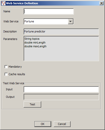
The Web Service Definition dialog box appears. Use this dialog box as follows:
Enter a name for your transformation. This name is displayed in the Map Component Tree pane and in the Graphical Map Builder pane.
Select the Web service that you want to use for this transformation. This list is populated with the RPC Web Services that are configured in the Oracle DataLens Server.
Populated with the description of the selected Web service from the Oracle DataLens Server.
Populated with the parameters of the selected Web service from the Oracle DataLens Server
Selecting this option results in an empty return from the Web service being considered an error condition.
Selecting this option results in the Web service caching the results of calls to it. If the same result is required, the result is retrieved from cache and an additional call to the Web service is not made. The cache remains in effect for the duration of the DSA job run.
The Test Web Service controls are provided to help you test the Web service connection. After adding a name for the transform, you can test the data source definition by typing a data value into the Input field then clicking Test. The test input should be entered with spaces separating multiple parameters. If the parameter is embedded, spaces use double quotes around the parameter. The results are displayed in the Output field.
Database transforms are defined by the database used. The Transformation Map Builder supports input from existing Oracle, MySQL, PostgreSQL, or SQL Server databases. Coupled with Lens and Item Definition transforms, this capability allows multiple data sources to be appropriately aggregated.
Transformation Maps can access information stored in a database and use that information to transform data. This database information can also be merged into the transformation flow, which allows you to aggregate several separate data sources.
To create a DB Transform, from the Edit menu, select Create DB Transformation or use the button of the same name.
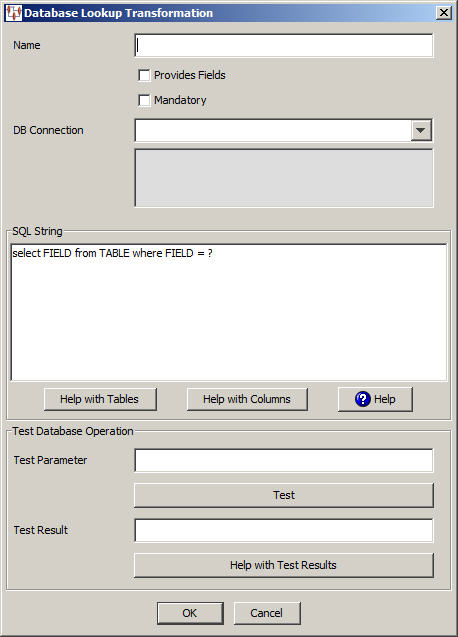
The Database Lookup Transformation dialog box appears. Use this dialog as follows.
Enter a name for your transformation. This name is displayed in the Map Component Tree pane and in the Graphical Map Builder pane.
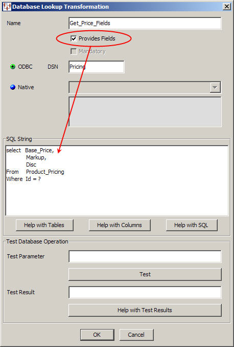
Select this check box to indicate that this database query returns multiple fields to the map. When selected, the Mandatory check box is not active because the fields that are returned are determined by those in the database.
Select this check box to define the quality of the database transformation. At run-time this transformation is success if the query returns a result, otherwise the record being processed is routed to the exception file.
You must select the type of database connection that you want to use. The list of database connections is populated based on those that you are configured in the Oracle DataLens Server. If the type of database connection is not listed, you must configure it in the Oracle DataLens Server so that it is available for selection when creating Transformation Maps.
Use the SQL String section to construct your database query with standard SQL query statements and syntax. For example, to determine if the inventory part numbers in your input data are an exact match to a standardized set of manufacturing part numbers you could use the following SQL statements:
SELECT 'Exact Match Mfg Std PN'||'|'|| inventory_item_id as match_type
FROM xyz_mfg_part_numbers_all_v
WHERE upper(mfg_part_num) = upper(&?3&)
AND upper(manufacturer_name) = upper(&?2&)
AND organization_id = &?1&
AND end_date is null;
This select clause must be compatible with your database. Optionally, you can use a question mark (?) in the select clause. At run-time, the question mark character is replaced with the transformation input data. This allows you to create a database transformation that varies with the content of the record being processed. Additionally, when database transforms are used to aggregate data fields from several different data sources, common access key information can be used across all data sources.
Use this button for assistance with the tables that are being used for the DB transformation.
The Database Table Help dialog appears. You can select a table name in the Tables list and view the columns for that table in the Columns list. You can copy information from either list to paste into the SQL String field. One table can be copied in the Tables list; one or multiple columns can be selected in the Columns list. Click the appropriate Copy button for the information you want to copy to the clipboard and click Close. When you are returned to the Database Lookup Transformation dialog box, use Ctrl-V to insert the copied information into the SQL String field at the insertion point.
Use this button for assistance with the columns that are being used for the DB transformation.
The Database Columns Assistance dialog appears. You can enter a table name in the Name field, click OK, and view the columns for that table. Then you can copy one or multiple columns names to the clipboard using the Copy button. Click Close to return to the Database Lookup Transformation dialog box and use Ctrl-V to insert the copied information into the SQL String field at the insertion point.
Select this button to view brief SQL query explanations and examples.
The Test Query fields are provided to help you test the setup of the data source connection. After you have entered a name, you can test the data source definition by typing a data value into the Test Parameter field and clicking the Test Query button. The test data value you entered is substituted for the question mark character(s) in the query string, and then the query is executed. The query results are displayed in the Test Result field.
When the query returns more than one record, the database transformation uses only the first record returned.
If there is an error in the connection definition, an information error message appears. Click the Help with Test Results button for help in interpreting error messages.
Note:
The following message indicates that the database connection tested good and is not an error message:Please check your database now
If an error message is received and there are no results in the Test Result field, the connection is good and the query is valid, but no matching results were returned.
This example shows how to configure a DB Transformation whose query returns only one field. It selects the price of an item from a database based on its ID. This DB transformation example is named Get_Price. It uses the data source named Pricing, and a query string that selects the base price from a database using the input ID column. The input ID column is represented in the query string as a question mark (?). At run-time, Application Studio uses the ID value from the record being process to access the database per the Map definition.
Create a DB Transform, right-click in the Map Component Tree pane, select Create DB Transformation.
Click OK.
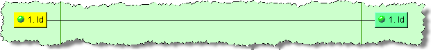
This DB Transform is placed in the Map, and then connected to the input ID column by dragging it and dropping it on a node in that column.
To connect single-field database transformations to the input column, you simply drag-and-drop the database transformation onto the target node in the Map to use the field output from the database query.
You can use several fields from a database transformation by simply selecting the Provides Fields check box as previously described. You must setup your query string to select the required multiple fields. This example retrieves the base price, markup, and discount from a pricing database.
Create a DB Transform, right-click in the Map Component Tree pane, select Create DB Transformation.
Select Provides Fields.
Click OK.
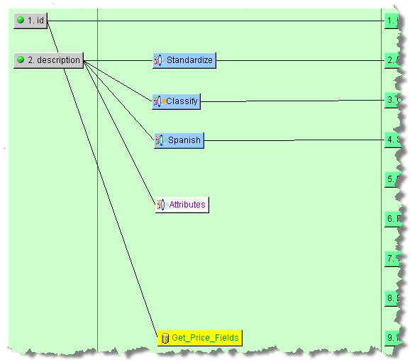
The resulting database transformation is placed in the map and connected to the ID input node.
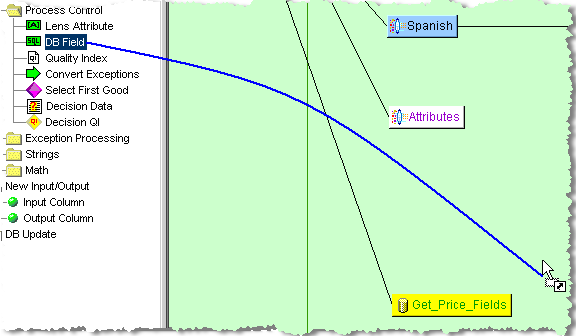
The DB Field control is used to extract the query results from the database transformation.
To add DB Field controls, you must first select the database transformation that will be automatically connected to it by clicking on it.
In this case, the Get_Price_Fields transform is selected in the Graphical Map Builder pane and is colored yellow.
Drag and drop the DB Control from the Map Component Tree pane into the Transformation column of the Graphical Map Builder pane.
The Select Database Attribute dialog appears listing all of the database fields available from the define query.
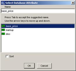
Note:
Because Application Studio attempts to read the list of fields directly from the defined database connection and query, an error occurs if your database connection and query are not correctly setup. If you are having trouble with your database connection, contact your IT professional.Creating connections between the database fields and the data source is done by selecting the attribute in this dialog and clicking OK.
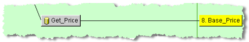
The selected DB node is automatically connected to its data source. In this example, the base_price node is automatically connected the Get_Price_Fields DB node.
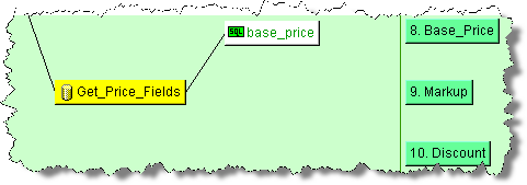
All DB Fields can be connected to other nodes in your map in this manner.
The Output column is the final step in defining a Transformation Map and defines the data that will be passed to the other applications within Enterprise DQ for Product.
One of the ways you can create an output node is using an input node as the basis. For more information, see "Creating Output Nodes from Input Nodes". These output nodes contain a single piece of data in either a text or SQL database field.
Alternatively, you can manually create output nodes by dragging the Output Column node from the Map Component Tree pane into the Output column of the Graphical Map Builder pane or pressing Ctrl-O anywhere in the map. The output type is selected automatically based on the type of map: text, database, or XML. For information about how use Item Definition output nodes, see "Creating Item Definition Output Nodes".
You are prompted for a name for the node and when you click OK the new node appears in the Output column of your map ready to be connected to an input or transformation node.
Note:
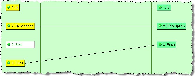
Similar to other naming restrictions, output column names cannot contain spaces or special characters.Once you have created an output node, you connect it to an input or a transformation node by dragging one of these nodes and dropping it onto the output node.
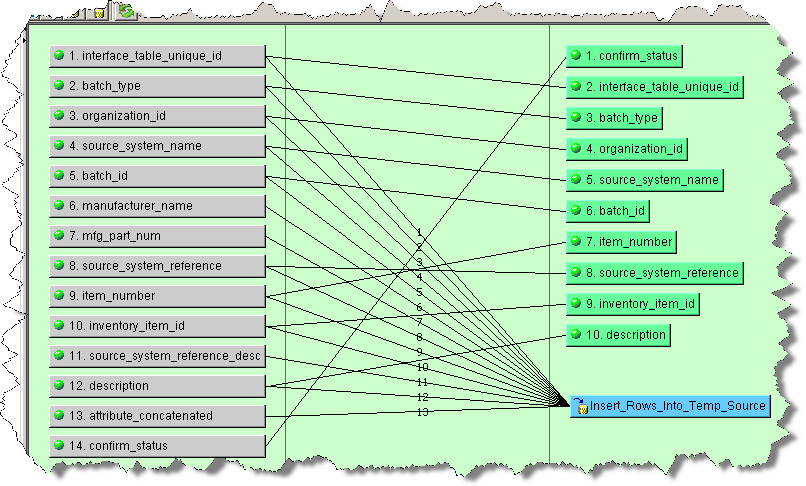
When you connect two or more nodes to one node, the connection lines are sequentially numbered. This allows you to discern the connections between nodes easily, which is particularly useful when there are numerous nodes in your map.
To create an Item Definition Output, expand the New Input/Output folder in the Map Component Tree pane, then drag and drop Item Definition Output node onto the Transformation Map in the Output column of the Graphical Map Builder pane.
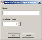
Enter a name for the output node, select (or enter) the number of attributes that this output node will create, and then click OK. You should enter a value in this field that exceeds the maximum number of attributes defined within the Item Definition. If only the first attribute should be created, enter a 1 as the attribute count. It is not necessary for Output node names to match Input node names.
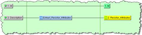
Once connected, the Item Definition Output node might look like the following:
The nodes that you have added to the transformation map columns can be modified using the functions described in this section.
Column nodes are placed in the map in the order in which they are created (automatically or manually) and can be moved by dragging and dropping a node to a different position in the column. This does not change the connections to other nodes; these connections remain intact and the connection lines are moved accordingly.

Though the example depicts moving output nodes, you can move any of the nodes in any column. The position number of the effected nodes changes to reflect the repositioning of a moved node.
You can edit the name and the field position number of existing input or output column nodes.
You can edit a node in any column, right-click on it, and then select Edit Column.
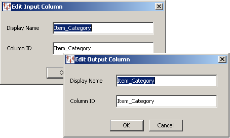
You can change the name that is displayed in the column using the Display field. The position label number can be changed using the Name field. Click OK to effect the changes and update the map column.
The connections to input and transformation nodes can be removed so that you can connect a transformation or Output node to another node.
You can disconnect a node from its incoming nodes, right-click on the node, and then select Disconnect Incoming. The lines connecting the selected node to any incoming nodes disappear, as well as the connections to the incoming data.
You can select a node or nodes and delete them if they are not required on the Transformation Map.
Delete one node by right-clicking on it, and then select Delete Node(s).
To select more than one input node, use the Shift (selecting continuously) or the Ctrl (selecting discontinuously) keys while selecting the nodes to be deleted. When all nodes are selected, right-click on one of the selected nodes and select Delete Node(s). The nodes are removed from the map.
This section details various examples of how you can process your data using some of the numerous transformation operations available.
The various attribute and field widgets are described in Attributes& Fields Widgets. These widgets are directly connected to a particular Lens Transform to process the data.
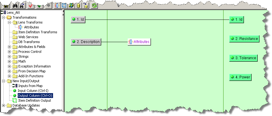
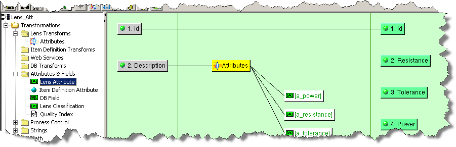
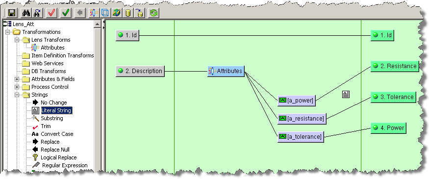
In this example, a Lens Transform named Attributes has been defined with the Provides Attributes option set to populate the Resistance, Power, and Tolerance output column nodes. Data lens attributes are directly associated with Lens Transforms, unlike DB Fields that are associated with a defined database transformation.
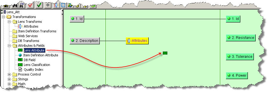
The next step in extracting the attribute text into the correct output columns is to add data lens attribute controls to the map. When adding data lens attribute controls, you must first select the data lens transformation associated with the data lens attribute control.
To make this association, click the Attributes transform in the Graphical Map Builder pane to select it; it changes color to yellow. Next, from the Map Component Tree pane, drag-and-drop the Lens Attribute node into the transformation column of the Graphical Map Builder pane.
The Select Attribute for Lens dialog box appears. This dialog lists all of the phrases and terms found in the data lens used by the selected Lens Transform. In this case, the Attributes transformation attributes are listed.
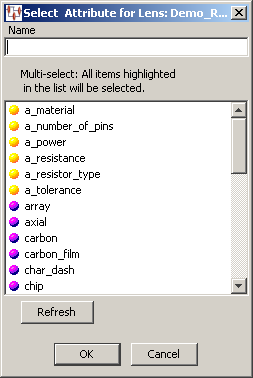
As you enter text in the Name field, the Application Studio automatically selects the closest phrase or term match from the list and takes you to that item. You can use the Tab key to complete the phrase or term name you have begun in the Name field.
You select one or more items from the list to add attributes to your map; selecting multiple items creates a Lens Attribute node for each.
Tip:
If the data lens has been updated and selected into the DataLens Administrator since you started your Transformation Map Builder session, you may need to use the Refresh button on this dialog to update your list of phrases and terms supplied by the data lens.Click OK to add the selected phrase or term rules to your map as a data lens attributes and connect them to the selected lens transformation.
The final step is to connect these attributes to their respective output columns as previously described, and then to save your map.

The various processing control widgets are described in Process Control Widgets. One of the most frequently used processing operations is to match data. For example, you may have data that you want to confirm whether it was found to be a match for a phrase rule. To do this you would use a match processing operation, which uses regular expressions to determine matching data.
From the Map Component Tree pane, drag and drop a Match widget into the transformation column of the Graphical Map Builder pane.
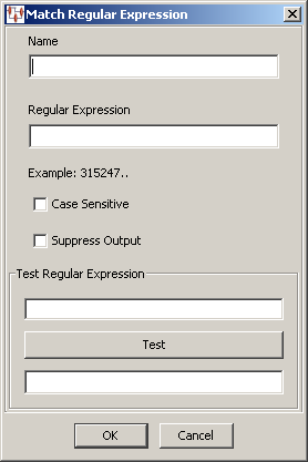
The Match Regular Expression dialog box appears. You provide the widget name, regular expression that you want to use for matching. Additionally, you can set the matching operation to be case sensitive or suppress any output results from being stored using the check boxes.
After you have entered defined the options, you can test the regular expression by entering a data value into the Test Regular Expression field and clicking Test. The test results are displayed in the Test Result field.
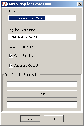
In the following example, the Check_Confirmed_Match Match widget is being created that identifies the data as a match if the uppercase expression CONFIRMED MATCH is encountered. It is set not to retain output data because the input data is processed by a subsequent DSA step.
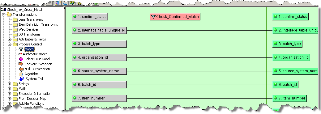
Once the Match widget is connected to the input and output nodes, it looks similar to the following:
The various string operators are described in Strings Widgets on page 76. This section provides some examples of how you might use string operators in your Transformation Maps.
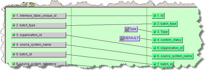
Literal Strings are used to add static text to your map transformation process. For example, if you want to add a label field for an attribute that was extracted by a Lens Transform, as in the Transforming Data Using Attributes and Fields example, you would use a Literal String widget and a corresponding Output node.
From the Map Component Tree pane, drag and drop a Literal String widget into the transformation column of the Graphical Map Builder pane.
The Literal String dialog box appears.
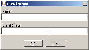
You are prompted for a Name and the static text that you want used. Next, you add an Output node to the Output column of the map and connect the two. In the following example, a label was created for the Resistance attribute column:
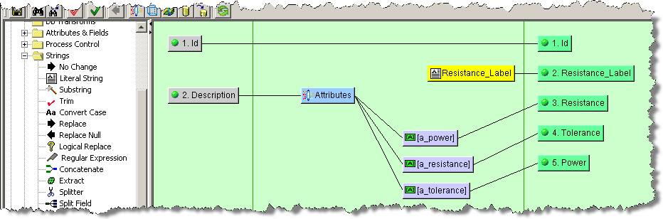
Another way to use the Literal String widget is simply to assign a specific string of static text to an Output node. The process is the same and may look similar to the following:
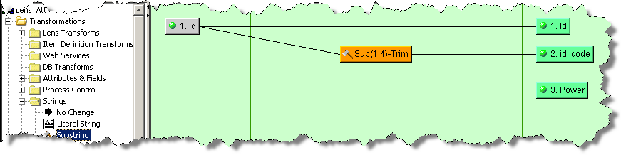
Substrings are used to extract a specific sub-set of characters from the input string. For example, if the first four characters of your ID column contain an important code that needs to be routed to a separate output column, you would use the substring operation to accomplish this.
From the Map Component Tree pane, drag and drop a Substring widget into the transformation column of the Graphical Map Builder pane.
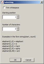
The Substring dialog box appears. Select the start position for the substring and number of characters you want to be in it. You can also trim any whitespace using the check box. Click OK, and then connect the Substring widgets to both the input and output nodes.
In the following example, the substring that will be created will start with the first character, contain four characters, and will not contain any whitespace if it is present within the four characters:
You can use this widget to replace any text using a logical expression. It is a powerful tool, particularly when using regular expressions.
From the Map Component Tree pane, drag and drop a Logical Replace widget into the transformation column of the Graphical Map Builder pane.
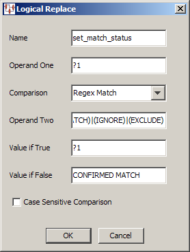
The logical replace compares value of Operand One against the value of Operand Two using the selected comparison. If the result is true, the value entered into the Value if True field is use as the output of this widget. Conversely, if the result is false the Value if False value is the output. These values can:
be literal (string or number) so are replaced with the entered values, or
indicate an input parameter in the form of ?1, ?2, ?3 and so on. This syntax forces the replace to use the first, second, and third inputs to the transformation during the comparison and generating the output. The ?number syntax can be used in any of the operand or value fields.
The comparison is a numeric comparison if both operands are numeric, or a string comparison if either operands are non-numeric. If a Regex Match comparison is selected, Operand Two is expected to be a valid regular expression, or the second run-time input must be a regular expression.
Tip:
Tooltips are available when hovering over one of the operand or value field names.In this example, Operand One indicates that the input data is going to be compared against the value of Operand Two using a regular expression. Because this is a regular expression comparison, the following delimited list was entered to see if the input data matched anything in the list:
(CONFIRMED CROSS REFERENCE)|(CONFIRMED NEW)|(CONFIRMED MATCH)|(IGNORE)|(EXCLUDE)
If the value is false, it is replaced with CONFIRMED MATCH; otherwise, the value remains unchanged so that it can be processed with perhaps a subsequent transformation column node.
For more information, see "Regular Expressions".
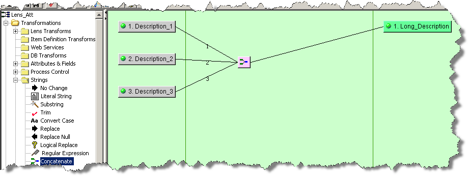
The Concatenate widget is used to merge multiple input strings to create one output string. The connected string inputs are merged top to bottom with a space between each string.
From the Map Component Tree pane, drag and drop a Concatenate widget into the transformation column of the Graphical Map Builder pane.
Connect the Concatenate widget to one or more input nodes and just one output node to create a concatenated string as in the following example:
The Extract widget can be used to retrieve a specific field to pass as output data.
From the Map Component Tree pane, drag and drop an Extract widget into the transformation column of the Graphical Map Builder pane.
The Extract Field dialog box appears.
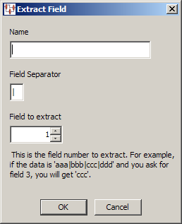
Enter a name for the widget, the symbol used to separate the fields, and the number of the field that you want extracted. Click OK to complete and add the Extract widget to the map, and then connect it to an output node to complete its use.
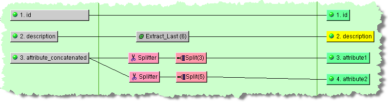
As in the preceding example, you can use the Splitter and Split Field widgets in conjunction to split the input data into chunks for multiple output nodes. They must be used in pairs for the output to operate correctly. You add the Splitter widget first then the Split widget, which allows you to select the number of characters of data that will be retrieved. These nodes are connected together, and to the input node. Each of the Split widgets is connected to the appropriate output nodes.
Note:
The count selected for each of the Extract and Split widgets, the number of fields, and number of characters respectively, appear next to the widget name in parenthesis for quick identification.The various string operators are described in Math Widgets on page 79. All of the math operators function in a similar manner by transforming the input numbers to a different output number using a designated math operator.
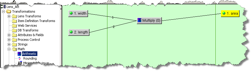
From the Map Component Tree pane, drag and drop a Math widget into the transformation column of the Graphical Map Builder pane.
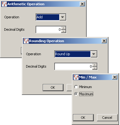
The selected math operation dialog box appears. Select the arithmetic operation you want to use and the number of decimal digits that the output will be calculated to, or select minimum or maximum. Click OK to add the Math widget to the map, and then connect the input and output nodes to it as in the following example:
During the design of a map and upon completion, you should test and validate it to ensure that it will operate properly. This section describes these two functions.
To test the open map, select Test Map from the Transform menu or click the button of the same name on the toolbar.
Note:
If you have unsaved changes or errors are found when the save is attempted, you are alerted and can choose to correct these errors by clicking No or Cancel.Note:
Maps that contain decision Item Definitions cannot be tested.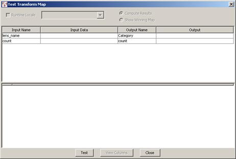
This Test Transformation Map dialog box appears.
Click Test to review your testing results.
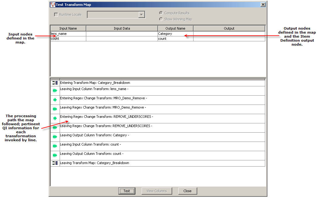
You can enter data into any of the Input Data fields then click the Test button to view the results in the corresponding Output field. This can help you verify the operation of the map and isolate any errors that may exist. Click Close to conclude testing.
Validating a Transformation Map ensures that the map steps and all columns connect properly; this is internal to the map. Any errors that require correction are identified with a brief explanation in an informational pop-up message.
To validate the open map, select Validate Map from the Transform menu or click the button of the same name on the toolbar. A message is displayed only if there are errors to be corrected in the map.
Transformation Maps that are defined in a DSA can be exported for use in other DSAs. This enables you to reuse a map repeatedly and avoids recreating the same function across various DSAs. For example, you could create one Transformation Map that queries a database for a given set of attributes and reuse it across a set of DSAs that are based on the same input data.
You can export a Transformation Map by selecting it in the DSA Component Tree pane and right-clicking on it, and then selecting Export Transform Map. The map is automatically saved to your DataLens\data\map directory and the file is named the same as the map.
Tip:
The Status Field shows you the full pathname of the Transform Map file that was saved.The Import Referenced Transformation Map option tells Application Studio to check its export directory for a transform of the same name. If one is found, that transform is imported to the current map. This is a very handy technique for copying Transformation Maps from one DSA to another: open the source DSA, export the desired transform, then open the destination map and select Import Referenced Transformation Maps.
The initial options that you set when defining a new Transformation Map may be changed when necessary as described in this section. Though the map options vary for the different Transformation Map types, they are accessed in the same manner.
From the Tools menu, select Map Options.
The text input (tab-separated files) Transformation Maps do not have configurable options.
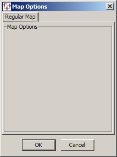
You can modify the original database query that you configured when creating your database map.
From the Tools menu, select Map Options.
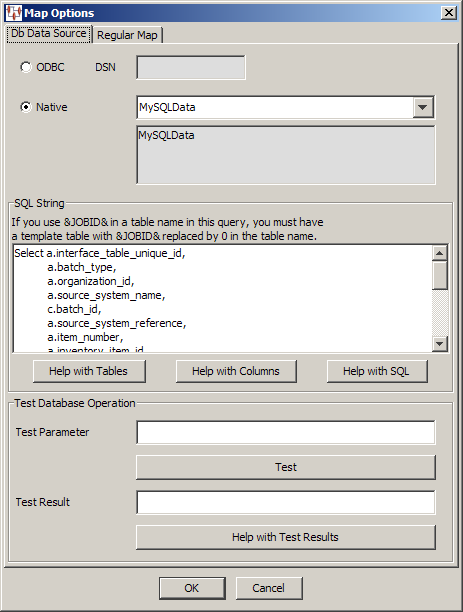
The Map Options dialog box is used as described in "Database Query Data Input". The Regular Map tab does not contain any options.
You can modify the original database query that you configured when creating your database map.
From the Tools menu, select Map Options.
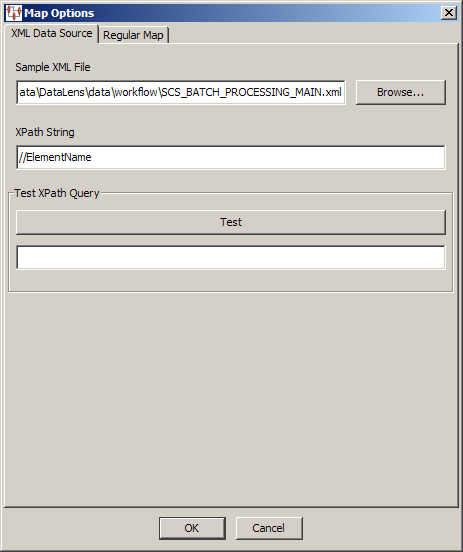
The Map Options dialog box is used as described in "XML Document Data Input". The Regular Map tab does not contain any options.
|
Copyright © 2001, 2011, Oracle and/or its affiliates. All rights reserved. Legal Notices |
|