| Skip Navigation Links | |
| Exit Print View | |

|
Sun Server X2-8 (formerly Sun Fire X4800 M2) Installation Guide Sun Server X2-8 (formerly Sun Fire X4800 M2) Documentation Library |
| Skip Navigation Links | |
| Exit Print View | |

|
Sun Server X2-8 (formerly Sun Fire X4800 M2) Installation Guide Sun Server X2-8 (formerly Sun Fire X4800 M2) Documentation Library |
Front and Back Features and Components
Unpacking the Server and Identifying the Rack Mounting Hardware
How to Identify Your Rack Mounting Kit
Installing the Server In the Rack Using the Standard Rack Mounting Kit
Contents of the Standard Rack Mounting Kit
Location of the Rack Mounting Kit and the Shipping Bracket Kit
Installing the Server In a Rack Using the Standard Rack Mounting Kit
Removing and Installing the Standard Rack Mounting Kit Shipping Brackets
Installing the Server in the Rack Using the Universal Rack Mounting Kit
Contents of the Universal Rack Mounting Kit
Installing the Server in a Rack Using the Universal Rack Mounting Kit
Installing and Removing the Universal Shipping Brackets
Removing the Server from the Rack
How to Remove the Server from the Rack
How to Remove the Rackmounting Hardware from the Rack
Attaching Administration (SP) Cables
Powering the Server On and Off
Getting Service for Your Server
How to Find the Server's Serial Number
Determining Your Server Management Strategy
Oracle Integrated Lights Out Manager
Oracle Hardware Management Pack
Oracle Hardware Installation Assistant
Configuring the Preinstalled Solaris Operating System
Configuring the Preinstalled Oracle Solaris OS
How to Connect to the Server Using the Server's IP Address
(Optional) How to Redirect the Console Output to the Video Port
How to Connect to the Server Using a Serial Capture Program
Oracle Solaris OS Information Products and Training
Configuring the Preinstalled Oracle Linux Operating System
Oracle Linux Configuration Worksheet
Configure the Preinstalled Oracle Linux OS
Register and Update Your Oracle Linux OS
Configuring the Preinstalled Oracle VM Software
Getting Started With Oracle VM
Communicating With Oracle ILOM and the System Console
About Oracle ILOM SP IP Addresses and the Oracle ILOM Interfaces
Connecting to the System Console
I/O and Interrupt Resource Allocation
Option ROM and I/O Space Allocation
How to Determine Whether You Need to Allocate Option ROM and I/O Space
Allocating MSI Interrupt Space (Oracle Solaris OS Only)
How to Identify and Fix Interrupt Resource Shortages
Sun Server X2-8 Specifications
Physical Specifications for the Sun Server X2-8
Power Specifications for the Sun Server X2-8
How to Request Physical Media Online
Before You Begin
Identify the devices on which you need to configure option ROM and/or I/O space allocation. See How to Determine Whether You Need to Allocate Option ROM and I/O Space.
F2 if you’re connected through a Java console.
Control-E if you’re connected through a serial console.
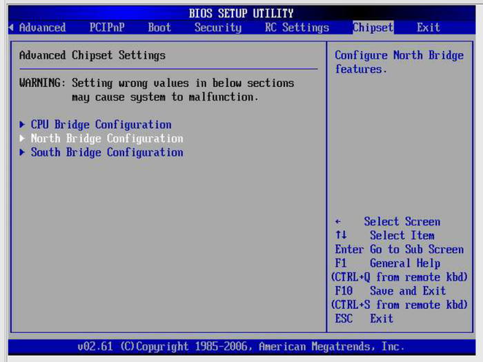
The BIOS setup menu appears.
Use the arrow and tab keys to navigate through the BIOS setup utility.
Use the Enter key to make selections.
When you are done, press F10, or navigate to the Exit menu screen to exit and save your changes.
The Advanced Chipset Settings screen appears.

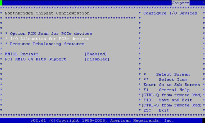
The NorthBridge Chipset Configuration screen appears.

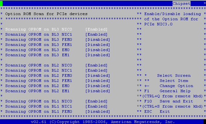
The Option ROM Scan appears.

Use the arrow keys to scroll down the list.
Use the Enter key to toggle your selections.
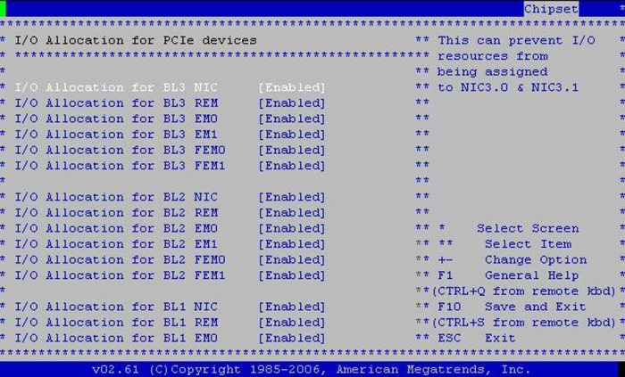
BIOS displays the I/O Allocation for all PCIe devices.

Enable any device you wish to boot from, and disable any device you do not wish to boot from.
Use the arrow keys to scroll down the list.
Use the Enter key to toggle your selections.
Note - This display includes all possible devices, including those that are not present.
The BIOS reallocates I/O space the next time the server boots.