| Skip Navigation Links | |
| Exit Print View | |

|
Sun Blade X3-2B Product Documentation |
Sun Blade X3-2B Model Name Change
Getting the Latest Firmware and Software
Hardware Installation and Product Notes
About the Chassis Monitoring Module (CMM)
Replaceable Server Module Components
Replaceable Components (FRUs and CRUs)
Preparing the Sun Blade X3-2B for Service
Obtaining the Server Module Serial Number
Powering Off the Server Module
Graceful Power Off Using the Power Button
Immediate Power Off Using the Power Button
Remote Power Off Using Oracle ILOM SP CLI
Remote Power Off Using Oracle ILOM SP Web Interface
Performing ESD and Antistatic Prevention Measures
Manage the Locate LED Remotely From Oracle ILOM SP Web Interface
Manage the Locate LED Remotely From Oracle ILOM CLI
Remove the Server Module from the Sun Blade Chassis
Remove the Server Module Top Cover
Removing or Inserting Filler Panels
Remove Server Module Filler Panels
Insert Server Module Filler Panels
Servicing Sun Blade X3-2B Components
Servicing a Storage Drive (CRU)
Identifying Storage Drive LEDs and Mechanical Components
About Storage Drive Failure and RAID
Remove Storage Drive Filler Panels
Insert Storage Drive Filler Panels
DIMM Population Rules and Guidelines
Remove Optional DIMM Filler Panels
Install Optional DIMM Filler Panels
Replace the System Battery (CRU)
Servicing USB Flash Drives (CRU)
Servicing a Fabric Expansion Module (CRU)
Servicing a RAID Expansion Module (CRU)
Replace a REM Battery on the REM Card
Remove the REM Storage Drive Cable
Install the REM Storage Drive Cable
Servicing a Processor and Heat Sink Assembly (FRU)
Processor Fault Remind Circuit
Clear Server Module Processor Faults
Servicing the Motherboard Assembly (FRU)
Remove and Install a Processor Cover Plate
Motherboard Assembly Replacement
Returning Sun Blade X3-2B to Operation
Install the Server Module Top Cover
Power On Using Oracle ILOM SP CLI
Power On Using Oracle ILOM SP Web Interface
Troubleshooting the Sun Blade X3-2B
Diagnosing Server Module Hardware Faults
Troubleshooting Using LED Status Indicators
Using the DIMM and Processor Test Circuit
Troubleshooting Server Module Power States
Troubleshoot Server Module Power Issues
Firmware and Software Troubleshooting
Recovering from Corrupted Service Processor Firmware
BIOS Power-On Self-Test (POST) Checkpoints
About POST Code Checkpoint Memory Testing
View BIOS POST Code Checkpoints Using Oracle ILOM Web Interface
View BIOS POST Code Checkpoints Using Oracle ILOM CLI
POST Code Checkpoint Reference
Getting Server Firmware and Software
Firmware and Software Access Options
Available Software Release Packages
Accessing Firmware and Software
Download Firmware and Software Using My Oracle Support
 | Caution - Component damage or personal injury. Blades can weigh up to 22 lbs (10kg). Use two hands to install or remove the blade from the chassis. |
Pull the lever out and eject the server module filler panel.
Do not discard the server module filler panel.
 | Caution - Over-temperature condition. Do not operate the chassis with empty slots. Always insert a server module filler panel into an empty slot within 60 seconds to reduce the possibility of server module shutdown due to overheating. |
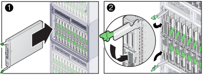
The following illustration shows the server module being inserted into the Sun Blade 6000 chassis. Your chassis might differ.

Note - After the server module is inserted into a powered-on chassis, all front panel LEDs blink three times.
The server module is now flush with the chassis, and the ejectors are locked.
If the chassis is powered on, the server module comes up to standby power. The green OK LED on the front panel blinks (0.2 seconds on, 2.8 seconds off).
Next Steps