2 Deploying the Connector
Deploying the connector involves the following steps:
Note:
In this guide, PeopleSoft Campus is referred to as the target system.
2.1 Preinstallation
Preinstallation information is divided across the following sections:
2.1.1 Determining the Version of PeopleTools and the Target System
You might want to determine the versions of PeopleTools and the target system you are using to check whether this release of the connector supports that combination. To determine the versions of PeopleTools and the target system:
2.1.2 Files and Directories on the Installation Media
Table 2-1 lists the files and directories on the installation media.
Table 2-1 Files and Directories on the Installation Media
| File in the Installation Media Directory | Description |
|---|---|
|
configuration/PSFT_Campus_Reconciliation-CI.xml |
This XML file contains configuration information that is used during connector installation. |
|
javadoc |
This directory contains information about the Java APIs used by the connector. |
|
lib/PSFT_CS-oim-integration.jar |
This JAR file contains the class files that are specific to integration of the connector with PeopleSoft target systems. During connector deployment, this file is copied to the Oracle Identity Manager database. |
|
lib/PSFTCommon.jar |
This JAR file contains PeopleSoft-specific files common to Campus, Employee Reconciliation, and User Management versions of the connector. During connector deployment, this file is copied to the Oracle Identity Manager database. |
|
The following files and directories in the listener directory: base directory lib/deploytool.jar build.xml deploy.properties README.txt |
The base directory contains the class files for the PeopleSoftOIMListener.ear file. This Enterprise Archive (EAR) file contains one or more entries representing the modules of the Web application to be deployed onto an application server. During connector deployment, the PeopleSoft listener is deployed as an EAR file. The deploytool.jar file contains the class files required for deploying the listeners. The build.xml file is the deployment script, which contains configurations to deploy the listener. The deploy.properties file contains Oracle Identity Manager connection details. The README.txt file contains instructions to deploy, remove, and redeploy the listener. |
|
Files in the resources directory |
Each of these resource bundles contains language-specific information that is used by the connector. During connector deployment, this file is copied to the Oracle Identity Manager database. Note: A resource bundle is a file containing localized versions of the text strings that are displayed on the Administrative and User Console. These text strings include GUI element labels and messages. |
|
test/config/log.properties test/config/reconConfig.properties |
These files are used by the InvokeListener.bat file. The reconConfig.properties file contains configuration information for running the InvokeListener.bat file. The log.properties file contains logger information. |
|
test/lib/PSFTTest.jar |
This JAR file is used by the testing utility for reconciliation. |
|
test/scripts/InvokeListener.bat test/scripts/InvokeListener.sh |
This BAT file and the UNIX shell script call the testing utility for reconciliation. |
|
xml/PeoplesoftCampus-ConnectorConfig.xml |
This XML file contains definitions for the connector components.
|
2.1.3 Preinstallation on the Target System
Permission lists, roles, and user profiles are building blocks of PeopleSoft security. Each user of the system has an individual User Profile, which in turn is linked to one or more Roles. To each Role, you can add one or more Permission Lists, which defines what a user can access. So, a user inherits permissions through the role that is attached to a User Profile.
You must create limited rights users who have restricted rights to access resources in the production environment to perform PeopleSoft-specific installation or maintenance operations.
The preinstallation steps consist of creating a user account with limited rights. Permission lists may contain any number of accesses, such as the Web libraries permission, Web services permissions, page permissions, and so on. You attach this permission list to a role, which in turn is linked to a user profile.
This section describes the following procedure, which has to be performed on the target system to create a user account with limited rights:
2.1.3.1 Creating a Target System User Account for Connector Operations
You must create a target system account with privileges required for connector operations. The user account created on the target system has the permission to perform all the configurations required for connector operations. This includes configuring the PeopleSoft Integration Broker for full reconciliation and incremental reconciliation. This account cannot access pages or components that are not required by the connector.
The following sections describe the procedures to create this target system account:
Note:
For creating the target system account, you must log in to PeopleSoft Internet Architecture with administrator credentials.
2.1.3.1.1 Creating a Permission List
To create a permission list:
-
Open a Web browser and enter the URL for PeopleSoft Internet Architecture. The URL is in the following format:
http://IPADDRESS:PORT/psp/ps/?cmd=loginFor example:
http://172.21.109.69:9080/psp/ps/?cmd=login
-
In the PeopleSoft Internet Architecture window, click PeopleTools, Security, Permissions & Roles, and then click Permission Lists.
-
Click Add a new Value. On the Add a New Value tab, enter the permission list name, for example,
OIMCS,and then click Add. -
On the General tab, enter a description for the permission list in the Description field.
-
On the Pages tab, click the search icon for Menu Name and perform the following:
-
Click the plus sign (+) to add a row for Menu Name. Click the search icon for Menu Name. In the Menu Name lookup, enter
IB_PROFILEand then click Lookup. From the list, select IB_PROFILE. The application returns to the Pages tab. Click Edit Components. -
On the Component Permissions page, click Edit Pages for each of the following component names:
IB_GATEWAY
IB_MESSAGE_BUILDER
IB_MONITOR_QUEUES
IB_NODE
IB_OPERATION
IB_QUEUEDEFN
IB_ROUTINGDEFN
IB_SERVICE
IB_SERVICEDEFN
IB_MONITOR
-
Click Select All, and then click OK for each of the components. Click OK on the Components Permissions page.
-
On the Pages tab, click the plus sign (+) to add another row for Menu Name.
-
In the Menu Name lookup, enter
PROCESSMONITORand then click Lookup. From the list, select PROCESSMONITOR. The application returns to the Pages tab. Click Edit Components. -
On the Component Permissions page, click Edit Pages for the PROCESSMONITOR component name.
-
Click Select All, and then click OK. Click OK on the Components Permissions page.
-
On the Pages tab, click the plus sign (+) to add another row for Menu Name.
-
In the Menu Name lookup, enter
PROCESS_SCHEDULERand then click Lookup. From the list, select PROCESS_SCHEDULER. The application returns to the Pages tab. Click Edit Components. -
On the Component Permissions page, click Edit Pages for the PRCSDEFN component name.
-
Click Select All, and then click OK. Click OK on the Components Permissions page.
-
On the Pages tab, click the plus sign (+) to add another row for Menu Name.
-
In the Menu Name lookup, enter
MANAGE_INTEGRATION_RULESand then click Lookup. From the list, select MANAGE_INTEGRATION_RULES. The application returns to the Pages tab. Click Edit Components. -
On the Component Permissions page, click Edit Pages for the EO_EFFDTPUB component name.
-
Click Select All, and then click OK. Click OK on the Components Permissions page. The application returns to the Pages tab.
-
-
On the People Tools tab, select the Application Designer Access check box and click the Definition Permissions link. The Definition Permissions page is displayed.
-
On this page, grant full access to the following object types by selecting Full Access from the Access list:
-
App Engine Program
-
Message
-
Component
-
Project
-
Application Package
-
-
Click OK.
-
Click the Tools Permissions link. The Tools Permissions page is displayed. On this page, grant full access to the SQL Editor tool by selecting Full Access from the Access list.
-
Click OK. The application returns to the People Tools tab.
-
On the Process tab, click the Process Group Permissions link. The Process Group Permission page is displayed.
-
In the Process Group lookup, click the search icon. From the list, select TLSALL.
-
On the Process Group Permission page, click the plus sign (+) to add another row for Process Group.
-
In the Process Group lookup, click the search icon. From the list, select STALL. The application returns to the Process Group Permission page.
-
Click OK.
-
On the Web Libraries tab, click the search icon for the Web Library Name field and perform the following:
-
In the Web Library Name lookup, enter
WEBLIB_PORTALand then click Lookup. From the list, select WEBLIB_PORTAL. The application returns to the Web Libraries tab. Click the Edit link. -
On the WebLib Permissions page, click Full Access(All).
-
Click OK and then click Save.
-
Click the plus sign (+) to add a row for the Web Library Name field and repeat Steps a through c for the WEBLIB_PT_NAV library.
-
Click Save to save all the settings specified for the permission list.
-
2.1.3.1.2 Creating a Role for a Limited Rights User
To create a role for a limited rights user:
-
Open a Web browser and enter the URL for PeopleSoft Internet Architecture. The URL is in the following format:
http://IPADDRESS:PORT/psp/ps/?cmd=loginFor example:
http:/172.21.109.69:9080/psp/ps/?cmd=login
-
In the PeopleSoft Internet Architecture window, click PeopleTools, Security, Permissions & Roles, and then click Roles.
-
Click Add a new Value. On the Add a New Value tab, enter the role name, for example,
OIMCS,and then click Add. -
On the General tab, enter a description for the role in the Description field.
-
On the Permission Lists tab, click the search icon and perform the following:
-
In the Permission Lists lookup, enter
OIMCSand then click Lookup. From the list, select OIMCS. -
Click the plus sign (+) to add another row.
-
In the Permission Lists lookup, enter
EOEI9000and then click Lookup. From the list, select EOEI9000.Note:
Permission list EOEI9000 is not available in PeopleTools 8.53, and is hence not applicable.
-
Click the plus sign (+) to add another row.
-
In the Permission Lists lookup, enter
EOCO9000and then click Lookup. From the list, select EOCO9000.
-
-
Click Save.
2.1.3.1.3 Assigning the Required Privileges to the Target System Account
To assign the required privileges to the target system account:
-
Open a Web browser and enter the URL for PeopleSoft Internet Architecture. The URL is in the following format:
http://IPADDRESS:PORT/psp/ps/?cmd=loginFor example:
http://172.21.109.69:9080/psp/ps/?cmd=login
-
In the PeopleSoft Internet Architecture window, click PeopleTools, Security, User Profiles, and then click User Profiles.
-
Click Add a new Value. On the Add a New Value tab, enter the user profile name, for example,
OIMCS,and then click Add. -
On the General tab, perform the following:
-
From the Symbolic ID list, select the value that is displayed. For example, SYSADM1.
-
Enter valid values for the Password and Confirm Password fields.
-
Click the search icon for the Process Profile permission list.
-
In the Process Profile lookup, enter
OIMCSand then click Lookup. From the list, select OIMCS. The application returns to the General tab.
-
-
On the ID tab, select none as the value of the ID type.
-
On the Roles tab, click the search icon:
-
In the Roles lookup, enter
OIMCSand then click Lookup. From the list, select OIMCS. -
Click the plus sign (+) to add another row.
-
In the Roles lookup, enter
ProcessSchedulerAdminand then click Lookup. From the list, select ProcessSchedulerAdmin. -
Click the plus sign (+) to add another row.
-
In the Roles lookup, enter
EIR Administratorand then click Lookup. From the list, select EIR Administrator.Note:
Role EIR Administrator is not available in PeopleTools 8.53, and is hence not applicable.
-
Click Save to save this user profile. This profile is also used for a person with limited rights in PeopleSoft for performing all reconciliation-related configurations.
-
2.2 Installation
Installation information is divided across the following sections:
2.2.1 Installation on Oracle Identity Manager
Installation on Oracle Identity Manager consists of the following procedures:
2.2.1.1 Running the Connector Installer
Note:
In this guide, the term Connector Installer has been used to refer to the Connector Installer feature of the Administrative and User Console.
To run the Connector Installer:
-
Create a directory for the connector, for example, PSFT_CS-11.1.1.5.0, in the OIM_HOME/server/ConnectorDefaultDirectory directory.
-
Copy the contents of the connector installation media directory into directory created in Step 1.
-
Depending on the Oracle Identity Manager release you are using, perform one of the following steps:
-
For Oracle Identity Manager release 11.1.1:
-
Log in to the Administrative and User Console by using the user account described in Creating the User Account for Installing Connectors in Oracle Fusion Middleware Administering Oracle Identity Manager.
-
On the Welcome to Identity Manager Advanced Administration page, in the System Management region, click Manage Connector.
-
-
For Oracle Identity Manager release 11.1.2.x:
-
Log in to Oracle Identity System Administration by using the user account described in Creating the User Account for Installing Connectors in Oracle Fusion Middleware Administering Oracle Identity Manager.
-
In the left pane, under System Management, click Manage Connector.
-
-
-
In the Manage Connector page, click Install.
-
From the Connector List list, select PeopleSoft Campus 11.1.1.5.0. This list displays the names and release numbers of connectors whose installation files you copy into the default connector installation directory in Step 1.
If you have copied the installation files into a different directory, then:
-
In the Alternative Directory field, enter the full path and name of that directory.
-
To repopulate the list of connectors in the Connector List list, click Refresh.
-
From the Connector List list, select PeopleSoft Campus 11.1.1.5.0.
-
-
Click Load.
-
To start the installation process, click Continue.
The following tasks are performed, in sequence:
-
Configuration of connector libraries
-
Import of the connector XML files (by using the Deployment Manager)
-
Compilation of adapter definitions
On successful completion of a task, a check mark is displayed for the task. If a task fails, then an X mark and a message stating the reason for failure is displayed. Depending on the reason for the failure, make the required correction and then perform one of the following steps:
-
Retry the installation by clicking Retry.
-
Cancel the installation and begin again from Step 1.
-
-
If all three tasks of the connector installation process are successful, then a message indicating successful installation is displayed. In addition, a list of steps that you must perform after the installation is displayed. These steps are as follows:
-
Configuring the IT resource for the connector
See Configuring the IT Resource for more information.
-
Configuring the scheduled tasks
See Configuring Scheduled Jobs for more information.
-
When you run the Connector Installer, it copies the connector files and external code files to destination directories on the Oracle Identity Manager host computer. These files are listed in Table 2-1.
2.2.1.2 Copying the Connector Files and External Code Files
Table 2-2 lists the files that you must copy manually and the directories on the Oracle Identity Manager host computer to which you must copy them.
If the connector files are extracted to the OIM_HOME/server/ConnectorDefaultDirectory/PSFT_CS-11.1.1.5.0/ directory on the Oracle Identity Manager host computer, then there is no need to copy these files manually.
Note:
-
The directory paths given in the first column of this table correspond to the location of the connector files in the PeopleSoft Campus directory on the installation media. See Files and Directories on the Installation Media for more information about these files.
If a particular destination directory does not exist on the Oracle Identity Manager host computer, then create it.
Table 2-2 Files to Be Copied to the Oracle Identity Manager Host Computer
| File in the Installation Media Directory | Destination for Oracle Identity Manager |
|---|---|
|
lib/PeopleSoftOIMListener.ear |
OIM_HOME/server/ConnectorDefaultDirectory/PSFT_CS-11.1.1.5.0/listener |
|
Files in the test/scripts directory |
OIM_HOME/server/ConnectorDefaultDirectory/PSFT_CS-11.1.1.5.0/scripts |
|
Files in the test/config directory |
OIM_HOME/server/ConnectorDefaultDirectory/PSFT_CS-11.1.1.5.0/config |
2.2.1.3 Configuring the IT Resource
The IT resource for the target system contains connection information about the target system. Oracle Identity Manager uses this information during reconciliation.
When you run the Connector Installer, the PSFT Campus IT resource is automatically created in Oracle Identity Manager. You must specify values for the parameters of this IT resource as follows:
-
Depending on the Oracle Identity Manager release you are using, perform one of the following steps:
-
For Oracle Identity Manager release 11.1.1:
Log in to the Administrative and User Console
-
For Oracle Identity Manager release 11.1.2.x:
Log in to Oracle Identity System Administration
-
-
If you are using Oracle Identity Manager release 11.1.1, then:
-
On the Welcome page, click Advanced in the upper-right corner of the page.
-
On the Welcome to Oracle Identity Manager Advanced Administration page, in the Configuration region, click Manage IT Resource.
-
-
If you are using Oracle Identity Manager release 11.1.2.x, and if you want to create a sandbox, then create application instance as follows:
See Also:
Oracle Fusion Middleware Developing and Customizing Applications for Oracle Identity Manager for more information about application instance and sandbox
-
On the upper navigation bar, click Sandboxes. The Manage Sandboxes page is displayed.
-
On the toolbar, click Create Sandbox. The Create Sandbox dialog box is displayed.
-
In the Sandbox Name field, enter a name for the sandbox. This is a mandatory field.
-
In the Sandbox Description field, enter a description of the sandbox. This is an optional field.
-
Click Save and Close. A message is displayed with the sandbox name and creation label.
-
Click OK. The sandbox is displayed in the Available Sandboxes section of the Manage Sandboxes page.
-
Select the sandbox that you created.
-
On the toolbar, click Activate Sandbox.
The table refreshes and a marker in the Active column is displayed. In addition, the Sandboxes link on the upper navigation bar also displays the active sandbox name in parentheses.
-
In the left pane, under Configuration, click Application Instances. The Application Instances page is displayed.
-
From the Actions menu, select Create. Alternatively, click Create on the toolbar. The Create Application Instance page is displayed.
-
Enter the values of the attributes. For example:
Name:
PeopleSoftInstanceDisplay Name:
PeopleSoftInstanceResource Object:
AffiliationIT Resource Instance:
PSFT Campus -
Click Save. The application instance is created, and the details of the application instance is displayed in a page.
-
To create a form to be associated with the application instance, open the Create Application Instance page or the Attributes tab of the Application Instance details page.
-
Adjacent to the Forms field, click Create. The Create Form page is displayed.
-
Enter values for the form attributes. For example:
Resource Type:
AffiliationForm Name:
CampusForm -
Click Create. A message is displayed stating that the form is created.
-
In the Create Application Instance page or the Attributes tab of the Application Instance details page, click Refresh adjacent to the Form field. The newly created form is available for selection in the Form list.
-
Select the new form from the drop-down list and click Apply.
The application instance is created.
-
Before publishing the sandbox, close all the open tabs and pages.
-
From the table showing the available sandboxes in the Manage Sandboxes page, select the sandbox that you created.
-
On the toolbar, click Publish Sandbox. A message is displayed asking for confirmation.
-
Click Yes to confirm. The sandbox is published and the customizations it contained are merged with the main line.
-
Search for and run the Catalog Synchronization Job scheduled job to sync the application instance with the catalog. See Configuring Scheduled Jobs for more information about configuring and running scheduled jobs.
-
-
In the left pane, under Configuration, click IT Resource.
-
In the IT Resource Name field on the Manage IT Resource page, enter
PSFT Campusand then click Search. Alternatively, from the IT Resource Type menu, select PSFT Campus, and then click Search. -
Click the edit icon for the IT resource.
-
From the list at the top of the page, select Details and Parameters.
-
Specify values for the parameters discussed in Table 2-3. The remaining parameters of IT resource are not applicable for this connector.
-
To save the values, click Update.
2.2.1.4 IT Resource Parameters
Specify values for the parameters discussed in Table 2-3.s
Table 2-3 IT Resource Parameters
| Parameter | Description |
|---|---|
|
Configuration Lookup |
This parameter holds the name of the lookup definition that contains configuration information. Default value: Note: You must not change the value of this parameter. However, if you create a copy of all the connector objects, then you can specify the unique name of the copy of this lookup definition as the value of the Configuration Lookup Name parameter in the copy of the IT resource. |
|
IsActive |
This parameter is used to specify whether the specified IT Resource is in use or not. Enter one of the following as the value of the IsActive parameter: Enter Enter Default value: |
2.2.1.5 Deploying the PeopleSoft Listener
The PeopleSoft listener is a Web application that is deployed on an Oracle Identity Manager host computer. The PeopleSoft listener parses the XML message and creates a reconciliation event in Oracle Identity Manager.
Note:
-
If you have already deployed a listener for the PeopleSoft User Management or Employee Reconciliation connector, then you must remove that listener and deploy the listener from the installation media of the PeopleSoft Campus connector.
-
The PeopleSoft Campus, PeopleSoft Employee Reconciliation, and PeopleSoft User Management connectors have different IT resources. Therefore, you must configure separate HTTP nodes for messages of the Campus, Employee Reconciliation, and User Management connectors.
Even if an existing node is configured to the PeopleSoft listener on Oracle Identity Manager, a separate node is required for messages of the PeopleSoft Campus connector.
-
If you are using IBM WebSphere Application Server, perform the procedure described in Deploying the PeopleSoft Listener on WebSphere Application Server.
This section contains the following topics:
-
Setting the Prerequisites of Deploying the PeopleSoft Listener
-
Deploying the PeopleSoft Listener on Oracle Identity Manager
-
Setting the Prerequisites of Deploying the PeopleSoft Listener on WebSphere Application Server
-
Deploying the PeopleSoft Listener on WebSphere Application Server
-
Importing Oracle Identity Manager CA Root Certificate into PeopleSoft WebServer
2.2.1.5.1 Setting the Prerequisites of Deploying the PeopleSoft Listener
Before deploying the PeopleSoft listener, perform the following steps:
-
Ensure Apache Ant 1.7 or later and JDK 1.6 or later are installed.
-
Set the following environment values in ant.properties:
-
ORACLE_HOME maps to the Oracle Identity Manager installation directory. For example,
/ps1/beahome/Oracle_IDM1 -
ORACLE_COMMON maps to the common directory in ORACLE_HOME. For example,
/ps1/beahome/Oracle_IDM1/common -
WLS_HOME maps to the WebLogic Server directory. For example,
/middleware/wlserver_10.3 -
JAVA_HOME maps to your JDK environment. For example,
/usr/local/packages/jdk16/ -
PATH must include the JAVA_HOME/bin directory. You can set the PATH variable using the
SET PATH=$JAVA_HOME/bin:$PATHcommand.
-
-
Build the wlfullclient.jar file in Oracle WebLogic server, for example, in the WLS_HOME/server/lib directory:
-
Change directories to WLS_HOME/server/lib.
-
Run the following command:
java -jar ../../../modules/com.bea.core.jarbuilder_1.3.0.0.jar
Note:
The exact jar file version can be different based on the WebLogic Server. Use the corresponding file with the name as
com.bea.core.jarbuilderat the WLS_HOME/../modules/ directory.
-
-
Start Oracle Identity Manager and the Admin Server.
2.2.1.5.2 Deploying the PeopleSoft Listener on Oracle Identity Manager
To deploy the PeopleSoft listener on Oracle Identity Manager:
Note:
If you need to deploy the listener in an Oracle Identity Manager cluster, then:
-
Specify the name of the cluster for the
oim.server.nameproperty in the listener/deploy.properties file. -
Update the following configurations appropriately with the URL of the listener, /PeopleSoftOIMListener:
-
Front-end web server
-
Load balancer
-
PeopleSoft nodes
-
-
Copy the connector package into the OIM_HOME/server/ConnectorDefaultDirectory directory of every node.
2.2.1.5.3 Setting the Prerequisites of Deploying the PeopleSoft Listener on WebSphere Application Server
Before deploying the PeopleSoft listener, ensure Apache Ant 1.7 or later and JDK 1.6 or later are installed. Then, set the following environment values in the ant.properties file:
-
OIM_ORACLE_HOME maps to the Oracle Identity Manager installation directory. For example,
/ps1/was/Oracle_IDM1You can set this variable using the
setenv OIM_ORACLE_HOME <value>command. -
JAVA_HOME maps to your JDK environment. For example,
/usr/local/packages/jdk16/You can set this variable using the
setenv JAVA_HOME <value>command. -
PATH must include the JAVA_HOME/bin directory. You can set this variable using the
setenv PATH $JAVA_HOME/bin:$PATHcommand.
2.2.1.5.4 Deploying the PeopleSoft Listener on WebSphere Application Server
To deploy the PeopleSoft listener on IBM WebSphere Application Server:
2.2.1.5.5 Importing Oracle Identity Manager CA Root Certificate into PeopleSoft WebServer
If you have configured SSL in Oracle Identity Manager, for the PeopleSoft listener to work in SSL you must import Oracle Identity Manager CA root certificate into PeopleSoft WebServer.
To do so, perform one of the following procedures depending on the PeopleSoft WebServer you are using:
-
For Oracle WebLogic Server:
-
Identity the certificate of issuing authority, the root CA for Oracle Identity Manager.
If you use the default demo certificate, then the root certificate is located in the following location:
MW_HOME/wlserver_10.3/server/lib/CertGenCA.der
If the certificate is issued by an external entity, then you must import the corresponding root certificate.
-
Use pskeymanager to import the root certificate into PeopleSoft WebServer keystore.
-
-
For IBM WebSphere Application Server:
-
Identity the certificate of issuing authority, the root CA for Oracle Identity Manager.
In the WebSphere Admin console, navigate to Security, SSL certificate and key management, Key stores and certificates, CellDefaultTrustStore, and Signer certificates. Then, select root and click Extract.
If the certificate is issued by a different entity, then you must import the corresponding root certificate.
-
Use pskeymanager to import the root certificate into PeopleSoft WebServer keystore.
-
2.2.1.6 Removing the PeopleSoft Listener
This section contains the following topics:
Note:
-
This section is not a part of installation on Oracle Identity Manager. You might need this procedure to extend the connector.
-
If you uninstall the connector, you must also remove the listener. Installing a new connector over a previously deployed listener creates discrepancies.
-
Do not remove the listener if the PeopleSoft User Management connector is installed and if it is using the listener.
2.2.1.6.1 Removing the PeopleSoft Listener for IBM WebSphere Application Server
To remove the PeopleSoft listener:
2.2.2 Installation on the Target System
During this stage, you configure the target system to enable it for reconciliation. This information is provided in the following sections:
2.2.2.1 Configuring the Target System for Full Reconciliation
As described in About the Connector, full reconciliation is used to reconcile all existing person data into Oracle Identity Manager.
Configuring the target system for full reconciliation involves creation of XML files for full reconciliation by performing the following procedures:
2.2.2.1.1 Configuring the PeopleSoft Integration Broker
The following sections explain the procedure to configure PeopleSoft Integration Broker:
2.2.2.1.1.1 Configuring PeopleSoft Integration Broker Gateway
PeopleSoft Integration Broker is installed as part of the PeopleTools installation process. The Integration Broker Gateway is a component of PeopleSoft Integration Broker, which runs on the PeopleSoft Web Server. It is the physical hub between PeopleSoft and the third-party system. The integration gateway manages the receipt and delivery of messages passed among systems through PeopleSoft Integration Broker.
To configure the PeopleSoft Integration Broker gateway:
2.2.2.1.1.2 Configuring PeopleSoft Integration Broker
PeopleSoft Integration Broker provides a mechanism for communicating with the outside world using XML files. Communication can take place between different PeopleSoft applications or between PeopleSoft and third-party systems. To subscribe to data, third-party applications can accept and process XML messages posted by PeopleSoft using the available PeopleSoft connectors. The Integration Broker routes messages to and from PeopleSoft.
To configure PeopleSoft Integration Broker:
-
Create a remote node as follows:
-
In PeopleSoft Internet Architecture, expand PeopleTools, Integration Broker, Integration Setup, and then click Nodes.
-
On the Add a New Value tab, enter the node name, for example,
OIM_FILE_NODE,and then click Add. -
On the Node Definition tab, provide the following values:
In the Description field, enter a description for the node.
In the Default User ID field, enter
PS. -
Make this node a remote node by deselecting the Local Node check box and selecting the Active Node check box.
-
Ensure that the Node Type is PIA.
-
On the Connectors tab, search for the following information by clicking the Lookup icon:
Gateway ID: LOCAL
Connector ID: FILEOUTPUT
-
On the Properties page in the Connectors tab, enter the following information:
Property ID: HEADER
Property Name: sendUncompressed
Required value: Y
Property ID: PROPERTY
Property Name: Method
Required value: PUT
Property ID: PROPERTY
Property Name: FilePath
Required value: Any location writable by the Integration Broker. This location is used to generate the full data publish files.
Property ID: PROPERTY
Property Name: Password
Required value: Same value as of ig.fileconnector.password in the integrationGateway.properties file
Note:
To locate the intergrationGateway.properties file, perform the following steps using the PeopleSoft administrator credentials:
-
In PeopleSoft Internet Architecture, expand PeopleTools, Integration Broker, Configuration, and then click Gateways.
-
In the Integration Gateway ID field, enter
LOCAL,and then click Search. -
Click the Gateway Setup Properties link.
You are prompted to enter the user ID and password.
-
Specify the following values:
In the UserID field, enter the appropriate user ID.
In the Password field, enter the appropriate password.
-
-
Click Save.
-
Click Ping Node to check whether a connection is established with the specified IP address.
-
2.2.2.1.2 Configuring the SCC_CONSTITUENT_FULLSYNC Service Operation
The SCC_CONSTITUENT_FULLSYNC message contains the basic personal information about all the persons. This information includes the ID, First Name, Last Name, Affiliation Type, and other contact information.
To configure the SCC_CONSTITUENT_FULLSYNC service operation, perform the following procedures:
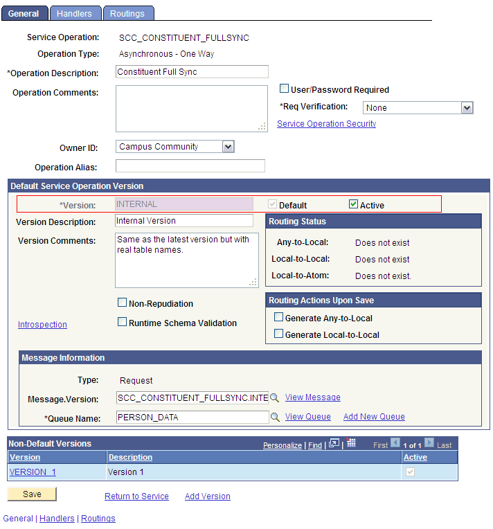
2.2.2.1.2.1 Activating the SCC_CONSTITUENT_FULLSYNC Service Operation
The service operation is a mechanism to trigger, receive, transform, and route messages that provide information about updates in PeopleSoft or an external application. You must activate the service operation to successfully transfer or receive messages.
To activate the SCC_CONSTITUENT_FULLSYNC service operation:
2.2.2.1.2.2 Verifying the Queue Status for the SCC_CONSTITUENT_FULLSYNC Service Operation
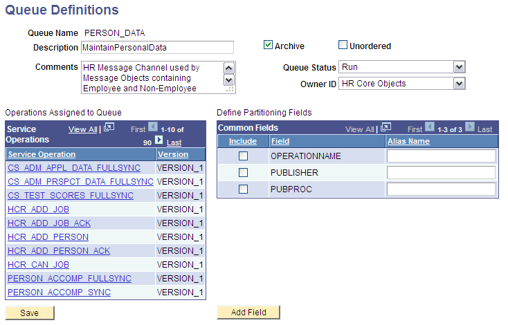
All messages in PeopleSoft are sent through a queue. This is done to ensure that the messages are delivered in a correct sequence. Therefore, you must ensure that the queue is in the Run status.
To ensure that the status of the queue for the SCC_CONSTITUENT_FULLSYNC service operation is Run:
-
In PeopleSoft Internet Architecture, expand PeopleTools, Integration Broker, Integration Setup, and then click Queues.
-
Search for the PERSON_DATA queue.
-
In the Queue Status list, ensure that Run is selected.
Note:
If the queue status is not Run:
-
From the Queue Status list, select Run.
-
Click Save.
The queue status is highlighted in the following screenshot:
-
-
Click Return to Search.
2.2.2.1.2.3 Setting Up the Security for the SCC_CONSTITUENT_FULLSYNC Service Operation
A person on the target system who has permission to modify or add personal or job information of a person might not have access to send messages regarding these updates. Therefore, it is imperative to explicitly grant security to enable operations.
To set up the security for SCC_CONSTITUENT_FULLSYNC service operation:
-
In PeopleSoft Internet Architecture, expand PeopleTools, Integration Broker, Integration Setup, and then click Service Operations.
-
Search for and open the SCC_CONSTITUENT_FULLSYNC service operation.
-
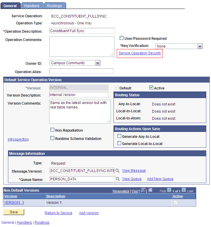
On the General tab, click the Service Operation Security link.
The link is highlighted in the following screenshot:
-
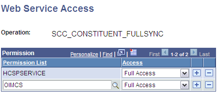
Attach the OIMCS permission list to the SCC_CONSTITUENT_FULLSYNC service operation. This list is created in Step 3 of the preinstallation procedure discussed in Creating a Permission List.
To attach the permission list:
-
Click the plus sign (+) to add a row to the Permission List field.
-
In the Permission List field, enter
OIMCSand then click the Look up Permission List icon.The OIMCS permission list appears.
-
From the Access list, select Full Access.
The following screenshot displays the preceding steps:
-
Click Save.
-
Click Return to Search.
-
2.2.2.1.2.4 Defining the Routing for the SCC_CONSTITUENT_FULLSYNC Service Operation
Routing is defined to inform PeopleSoft about the origin and intended recipient of the message. You might have to transform the message being sent or received according to the business rules.
To define the routing for SCC_CONSTITUENT_FULLSYNC service operation:
-
On the Routing tab, enter
SCC_CONSTITUENT_FULLSYNC_CS_FILEas the routing name and then click Add. -
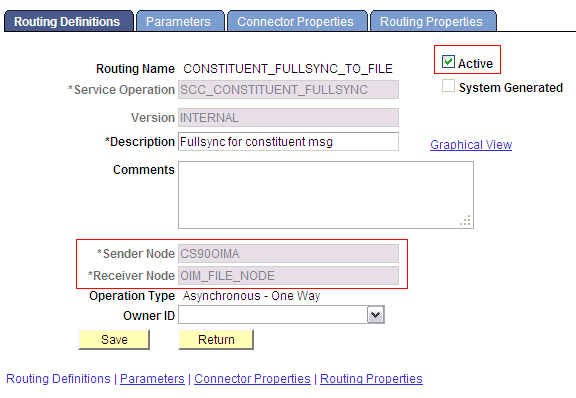
On the Routing Definitions tab, enter the following:
Sender Node:
PSFT_CSNote:
The Sender Node is the default active local node. To locate the sender node:
-
Click the Look up icon.
-
Click Default to sort the results in descending order.
The default active local node should meet the following criteria:
Local Node: 1
Default Local Node: Y
Node Type: PIA
Only one node can meet all the above conditions at a time.
-
Select the node.
-
Click Save.
Receiver Node:
OIM_FILE_NODEThe following screenshot displays the Sender and Receiver nodes:
-
-
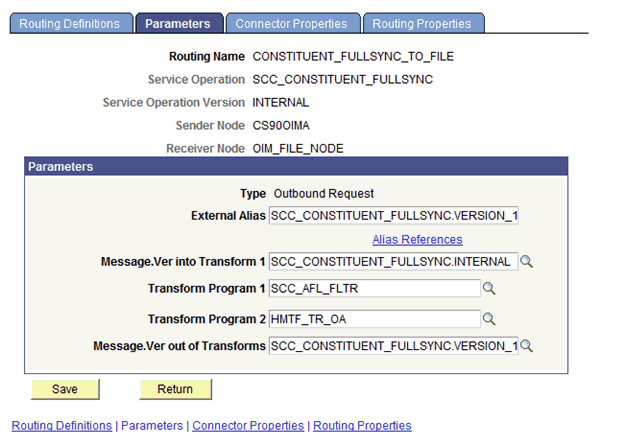
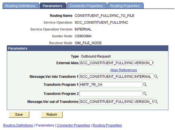
Click the Parameters tab and enter the following details in the fields:
-
External Alias:
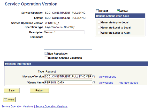
SCC_CONSTITUENT_FULLSYNC.VERSION_1 -
Message.Ver into Transform 1:
SCC_CONSTITUENT_FULLSYNC.INTERNAL -
Transform Program 1:
HMTF_TR_OAClick Cancel on the warning box that is displayed.
-
Message.Ver out of Transforms:
SCC_CONSTITUENT_FULLSYNC.VERSION_1
The following screenshot displays the Parameters tab:
-
-
Click Save.
-
Click Return to go back to the Routings tab of the service operation, and verify whether your routing is active.
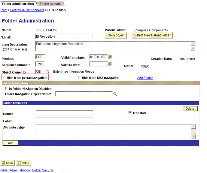
2.2.2.1.2.5 Displaying the EI Repository Folder
EI Repository is a hidden folder in PeopleSoft. Therefore, you must display this folder.
To display the EI Repository folder:
Note:
Perform this procedure using the PeopleSoft administrator credentials.
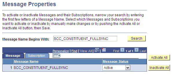
2.2.2.1.2.6 Activating the SCC_CONSTITUENT_FULLSYNC Message
You must activate the SCC_CONSTITUENT_FULLSYNC message so that it can be processed.
To activate the SCC_CONSTITUENT_FULLSYNC message:
2.2.2.1.2.7 Activating the Full Data Publish Rule
You must define and activate the Full Data Publish rule, because it acts as a catalyst for the full reconciliation process. This rule provides the full reconciliation process the desired information to initiate reconciliation.
To activate the full data publish rule:
-
In the PeopleSoft Internet Architecture, expand Enterprise Components, Integration Definitions, and then click Full Data Publish Rules.
-
Search for and open the SCC_CONSTITUENT_FULLSYNC message.
-
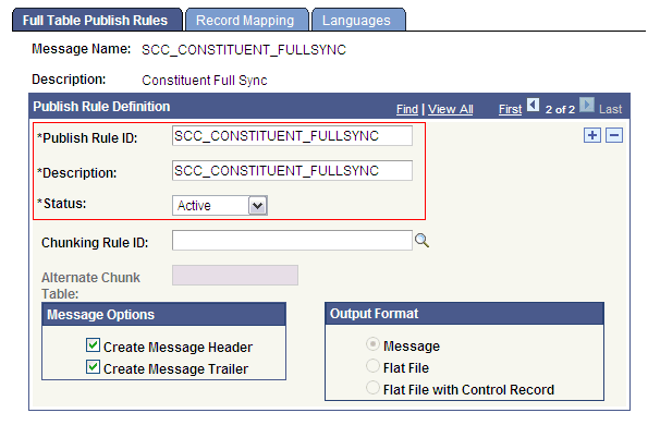
In the Publish Rule Definition region:
-
In the Publish Rule ID field, enter
SCC_CONSTITUENT_FULLSYNC. -
In the Description field, enter
SCC_CONSTITUENT_FULLSYNC. -
From the Status list, select Active.
The following screenshot displays the preceding steps:
-
-
Click Save.
2.2.2.2 Enabling Content-based Filtering for Full Reconciliation in SCC_CONSTITUENT_FULLSYNC Message
Content-based filtering uses PeopleSoft Campus Solutions Affiliations codes for publishing rules. Affiliation Codes represent the relationship(s) a person has with an institution. This section assumes that you have already configured the SCC_CONSTITUENT_FULLSYNC message by following the procedure described in Configuring the SCC_CONSTITUENT_FULLSYNC Service Operation.
The following procedures are discussed in this section:
2.2.2.2.1 Setting Affiliation Routing Rules
Using content-based filtering for the SCC_CONSTITUENT_FULLSYNC message requires that you define valid Affiliation Codes that you wish to include in the data sent to Oracle Identity Manager. Selecting Affiliation Codes allows you to define the scope of persons which will be included in the generated XML files.
Note:
Affiliation Codes are defined and set appropriately for persons in the PeopleSoft Campus Solutions target system. See PeopleSoft Campus Solutions documentation for more information about defining and using Affiliations.
To set Affiliate Routing rules:
2.2.2.2.2 Setting the Routing Transformation Parameters for the SCC_CONSTITUENT_FULLSYNC message
You will transform the message being sent by enabling an additional transform program on the Affiliation Routing parameters.
To define the routing for SCC_CONSTITUENT_FULLSYNC service operation:
2.2.2.2.3 Activating the Full Data Publish Rule with Content-based Filtering
You must define and activate the Full Data Publish rule that uses the Affiliation Routing settings you defined. This rule provides the full reconciliation process the desired information to initiate reconciliation.
To activate the full data publish rule:
-
In the PeopleSoft Internet Architecture, expand Enterprise Components, Integration Definitions, and then click Full Data Publish Rules.
-
Search for and open the SCC_CONSTITUENT_FULLSYNC message.
-
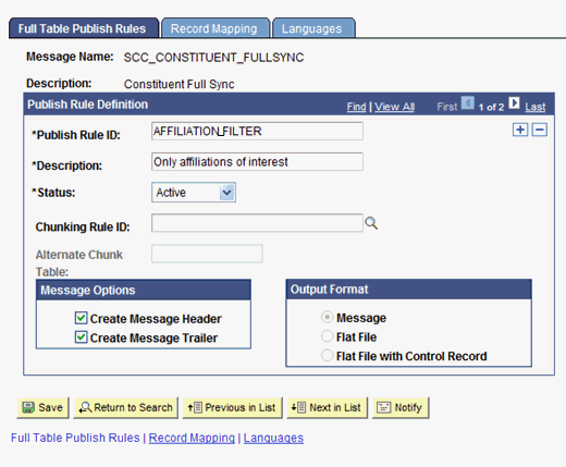
In the Publish Rule Definition region:
-
In the Publish Rule ID field, enter
AFFILIATION_FILTER. -
In the Description field, enter
Only affiliations of interest. -
From the Status list, select Active.
-
Verify in the Message Options box that Create Message Header and Create Message Trailer are selected.
The following screenshot displays the preceding steps:
-
-
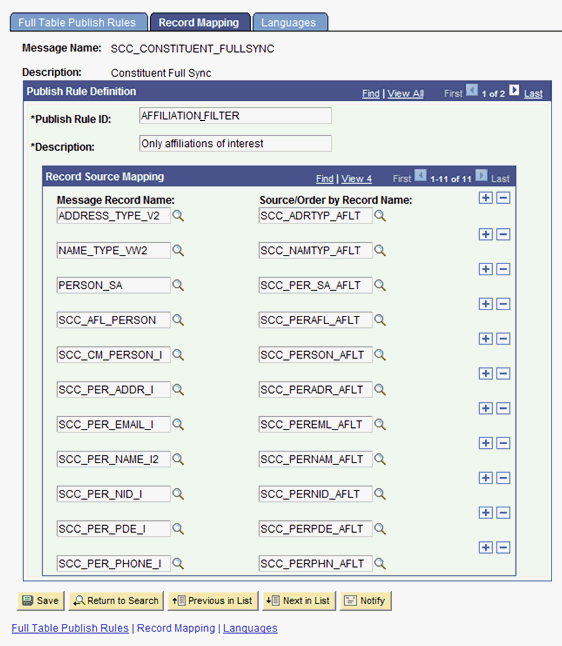
Click the Record Mapping tab.
-
In the Record Source Mapping region, enter the following values:
Message Record Name Source/Order by Record Name ADDRESS_TYPE_V2
SCC_ADRTYP_AFLT
NAME_TYPE_VW2
SCC_NAMTYP_AFLT
PERSON_SA
SCC_PER_SA_AFLT
SCC_AFL_PERSON
SCC_PERAFL_AFLT
SCC_CM_PERSON_I
SCC_PERSON_AFLT
SCC_PER_ADDR_I
SCC_PERADR_AFLT
SCC_PER_NAME_I2
SCC_PERNAM_AFLT
SCC_PER_NID_I
SCC_PERNID_AFLT
SCC_PER_PDE_I
SCC_PERPDE_AFLT
SCC_PER_PHONE_I
SCC_PERPHN_AFLT
The following screenshot displays the preceding steps:
-
Click Save.
2.2.2.3 Configuring the Target System for Incremental Reconciliation
Configuring the target system for incremental reconciliation involves configuring PeopleSoft Integration Broker and configuring the SCC_CONSTITUENT_SYNC messages.
A message is the physical container for the XML data that is sent from the target system. Message definitions provide the physical description of data that is sent from the target system. This data includes fields, field types, and field lengths. A queue is used to carry messages. It is a mechanism for structuring data into logical groups. A message can belong to only one queue.
Setting the PeopleSoft Integration Broker gateway is mandatory when you configure PeopleSoft Integration Broker. To subscribe to XML data, Oracle Identity Manager can accept and process XML messages posted by PeopleSoft by using PeopleSoft connectors located in the PeopleSoft Integration Broker gateway. These connectors are Java programs that are controlled by the PeopleSoft Integration Broker gateway.
This gateway is a program that runs on the PeopleSoft Web server. It acts as a physical hub between PeopleSoft and PeopleSoft applications (or third-party systems, such as Oracle Identity Manager). The gateway manages the receipt and delivery of messages to external applications through PeopleSoft Integration Broker.
To configure the target system for incremental reconciliation, perform the following procedures:
Note:
You must use an administrator account to perform the following procedures.
2.2.2.3.1 Configuring PeopleSoft Integration Broker
To configure PeopleSoft Integration Broker:
Note:
-
SectionConfiguring PeopleSoft Integration Broker Gateway describes the procedure to configure the PeopleSoft Integration Broker gateway.
-
The PeopleSoft Campus, PeopleSoft Employee Reconciliation, and PeopleSoft User Management connectors have different IT resources. Therefore, you must configure separate HTTP nodes for messages of the Campus, Employee Reconciliation, and User Management connectors.
Even if an existing node is configured to the PeopleSoft listener on Oracle Identity Manager, a separate node is required for messages of the PeopleSoft User Management connector.
-
A single listener is sufficient for all the connectors. However, you must remove any existing listeners and deploy the listener from the installation media of the PeopleSoft Campus connector. You can configure the nodes to point to the same listener with different IT resource names.
-
Create a remote node by performing the following steps:
-
In PeopleSoft Internet Architecture, expand PeopleTools, Integration Broker, Integration Setup, and then click Nodes.
-
On the Add a New Value tab, enter the node name, for example,
OIM_CS_NODE,and then click Add. -
On the Node Definition tab, enter a description for the node in the Description field. In addition, specify the SuperUserID in the Default User ID field. For example,
PS. -
Make this node a remote node by deselecting the Local Node check box and selecting the Active Node check box.
-
Ensure Node Type is PIA.
-
On the Connectors tab, search for the following information by clicking the Lookup icon:
Gateway ID: LOCAL
Connector ID: HTTPTARGET
-
On the Properties page in the Connectors tab, enter the following information:
Property ID: HEADER
Property Name: sendUncompressed
Required value: Y
Property ID: HTTP PROPERTY
Property Name: Method
Required value: POST
Property ID: HEADER
Property Name: Location
Required value: Enter the value of the IT Resource name as configured for PeopleSoft Campus
Sample value: PSFT Campus
Property ID: PRIMARYURL
Property Name: URL
Required value: Enter the URL of the PeopleSoft listener that is configured to receive XML messages. This URL must be in the following format:
http://ORACLE_IDENTITY_MANAGER_SERVER_IPADDRESS:PORT/PeopleSoftOIMListener
The URL depends on the application server that you are using. For an environment on which SSL is not enabled, the URL must be in the following format:
For IBM WebSphere Application Server:
http://10.121.16.42:9080/PeopleSoftOIMListener
For Oracle WebLogic Server:
http://10.121.16.42:7001/PeopleSoftOIMListener
For an environment on which SSL is enabled, the URL must be in the following format:
https://COMMON_NAME:PORT/PeopleSoftOIMListener
For IBM WebSphere Application Server:
https://example088196:9443/PeopleSoftOIMListener
For Oracle WebLogic Server:
https://example088196:7002/PeopleSoftOIMListener
Note:
The ports may vary depending on the installation that you are using.
-
Click Save to save the changes.
-
Click the Ping Node button to check whether a connection is established with the specified IP address.
Note:
Ping also validates the target authentication, in this case, the IT resource name.
-
Before the XML messages are sent from the target system to Oracle Identity Manager, you must verify whether the PeopleSoft node is running. You can do so by clicking the Ping Node button in the Connectors tab. To access the Connectors tab, click PeopleTools, Integration Broker, Integration Setup, and then Nodes.
Note:
You might encounter the following error when you send a message from PeopleSoft Integration Broker over HTTP PeopleTools 8.50 target system:
HttpTargetConnector:PSHttpFactory init or setCertificate failed
You might also encounter the following error when you ping the node:
Cannot establish HTTP connection
This happens because the Integration Broker Gateway Web server tries to access the keystore even if SSL is not enabled using the parameters defined in the integrationgateway.properties file as follows:
secureFileKeystorePath=<path to pskey>
secureFileKeystorePasswd=password
To find the integrationgateway.properties file, go to PeopleTools, Integration Broker, Configuration, Gateways, and then click Gateway Setup Properties.After logging in, click on the Advanced Properties Page link
If either the <path to pskey> or the password (unencrypted) is incorrect, you will receive the preceding error message. Perform the following steps to resolve the error:
-
Verify if
secureFileKeystorePathin the integrationgateway.properties file is correct. -
Verify if
secureFileKeystorePasswdin the integrationgateway.properties file is correct. -
Then, find the
secureFileKeystorePasswdoption and copy the password down to the Password Encryption box. Next, click Encrypt to get your encrypted version. -
Finally, copy the encrypted version back up to the setting.
-
Save and exit.
Usually, a new PeopleTools 8.50 instance throws the preceding error when you message over the HTTP target connector. The reason is that the default password is not in the encrypted format in the integrationgateway.properties file.
For more information, see https://support.oracle.com/epmos/faces/ui/km/DocumentDisplay.jspx?id=1270683.1
2.2.2.3.2 Configuring the SCC_CONSTITUENT_SYNC Service Operation
The SCC_CONSTITUENT_SYNC message contains the updated information about a particular person. This information includes the Employee ID and the information that is added or modified.
To configure the SCC_CONSTITUENT_SYNC service operation perform the following procedures:
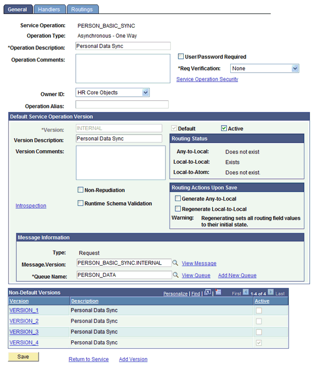
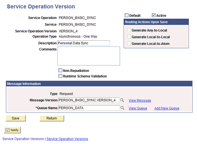
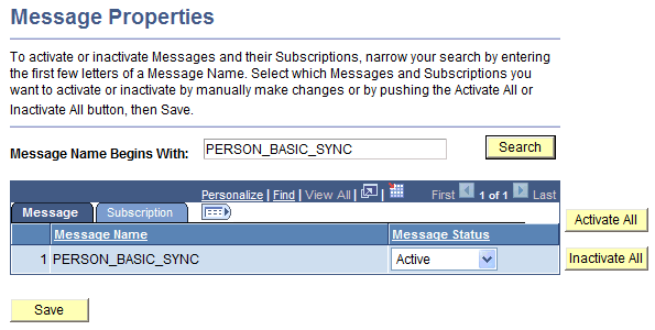
2.2.2.3.2.1 Activating the PERSON_BASIC_SYNC Service Operation
To activate the PERSON_BASIC_SYNC service operation:
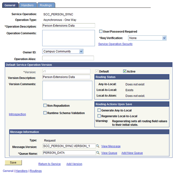
2.2.2.3.2.2 Activating the SCC_PERSON_SYNC Service Operation
To activate the SCC_PERSON_SYNC service operation:
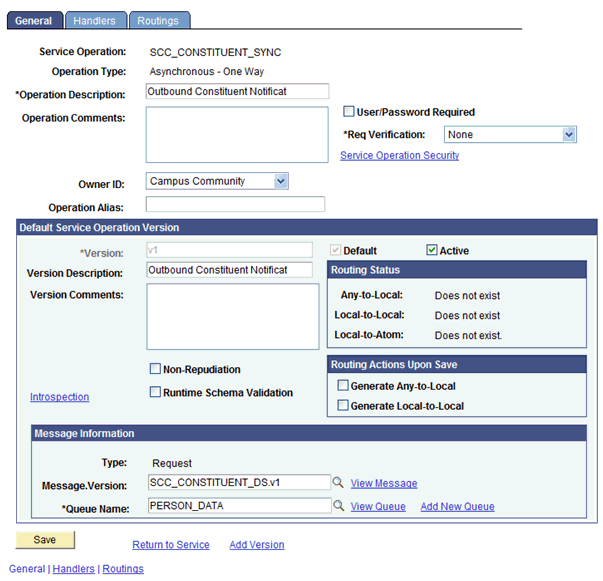
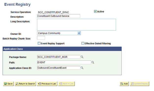
2.2.2.3.2.3 Activating the SCC_CONSTITUENT_SYNC Service Operation
To activate the SCC_CONSTITUENT_SYNC service operation:
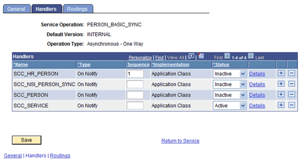
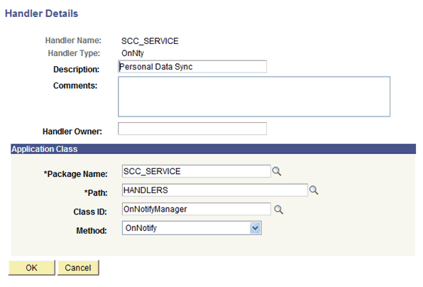
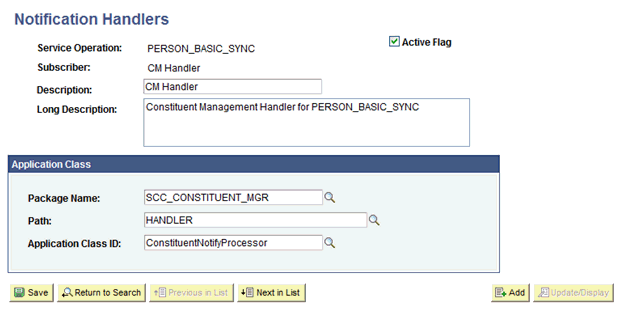
2.2.2.3.2.5 Activating the PERSON_BASIC_SYNC Notification Handler
To activate PERSON_BASIC_SYNC notification handler:
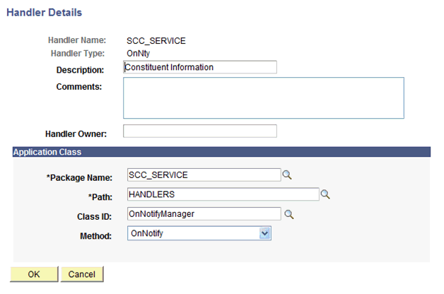
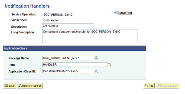
2.2.2.3.2.6 Activating the SCC_PERSON_SYNC Notification Handler
To activate SCC_PERSON_SYNC notification handler:
2.2.2.3.2.7 Verifying the Queue Status for the SCC_CONSTITUENT_SYNC Service Operation
To ensure that the status of the queue for the SCC_CONSTITUENT_SYNC service operation is Run:
-
In PeopleSoft Internet Architecture, expand PeopleTools, Integration Broker, Integration Setup, and then click Queues.
-
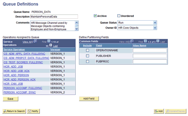
Search for the PERSON_DATA queue.
-
In the Queue Status list, ensure that Run is selected.
Note:
If the queue status is not Run:
-
From the Queue Status list, select Run.
-
Click Save.
The PERSON_BASIC_SYNC and SCC_PERSON_SYNC service operations also use this queue.
The queue status is shown in the following screenshot:
-
-
Click Return to Search.
2.2.2.3.2.8 Setting Up the Security for Service Operations
Perform this procedure for each of the following service operations:
-
PERSON_BASIC_SYNC
-
SCC_PERSON_SYNC
-
SCC_CONSTITUENT_SYNC
To set up the security for the PERSON_BASIC_SYNC service operation:
-
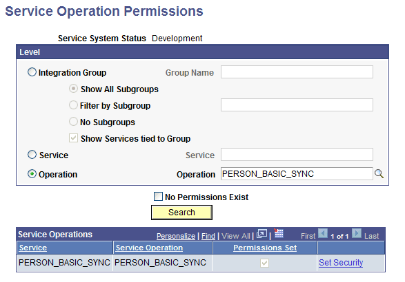
In PeopleSoft Internet Architecture, expand PeopleTools, Integration Broker, Service Utilities, and then click Service Operation Permissions.
-
In the Operation field, enter
PERSON_BASIC_SYNCand click Search. -
In the Service Operations region, click the Set Security link, as shown in the following screenshot:
-
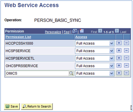
Attach the OIMCS permission list to the PERSON_BASIC_SYNC service operation. This list is created in Step 3 of the preinstallation procedure discussed in Creating a Permission List.
To attach the permission list:
Note:
This procedure describes how to grant access to the OIMCS permission list. The OIMCS permission list is used as an example. But, to implement this procedure you must use the permission list (attached through a role) to the user profile that has the privilege to modify personal data in the target system.
-
Click the plus sign (+) to add a row for the Permission List field.
-
In the Permission List field, enter
OIMCSand then click the Look up Permission List icon.The OIMCS permission list appears.
-
From the Access list, select Full Access.
The following screenshot displays the permission list with Full Access:
-
Click Save.
-
Click Return to Search.
-
-
Repeat the Steps 1 to 4 for the SCC_PERSON_SYNC and SCC_CONSTITUENT_SYNC service operations.
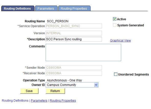
2.2.2.3.2.9 Defining the Routing for the SCC_CONSTITUENT_SYNC Service Operation
To define the routing for the SCC_CONSTITUENT_SYNC service operation:
-
On the Routing tab, enter
SCC_CONSTITUENT_SYNC_CS_OIMas the routing name and then click Add. -
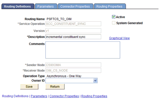
On the Routing Definitions tab, enter the following:
Sender Node:
PSFT_CSNote:
The Sender Node is the default active local node. To locate the sender node:
-
Click the Look up icon.
-
Click Default to sort the results in descending order.
The default active local node should meet the following criteria:
Local Node: 1
Default Local Node: Y
Node Type: PIA
Only one node can meet all the above conditions at a time.
-
Select the node.
-
Click Save.
Receiver Node:
OIM_CS_NODEThe following screenshot displays the Sender and Receiver nodes:
-
-
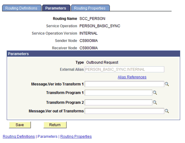
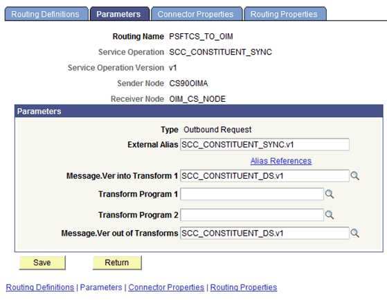
On the Parameters tab, verify that the following values are set as default:
-
In the External Alias field, enter
SCC_CONSTITUENT_SYNC.v1. -
In the Message.Ver into Transform 1 field, enter
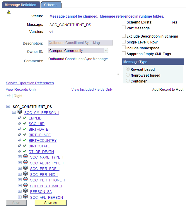
SCC_CONSTITUENT_DS.v1.The following screenshot displays the preceding steps:
-
In the Message.Ver out of Transforms field, enter
SCC_CONSTITUENT_DS.v1. -
Click Save.
-
Click Return to go back to the Routings tab of the Service Operation, and verify whether your routing is active.
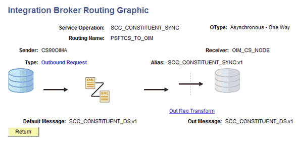
The following graphic displays the routing SCC_CONSTITUENT_SYNC_CS_OIM and its transformation:
-
2.2.2.3.2.10 Displaying the EI Repository Folder
To display the EI Repository folder:
Note:
-
If you have performed this procedure as described in Displaying the EI Repository Folder, then you can skip this section.
-
Perform this procedure using the PeopleSoft administrator credentials.
2.2.2.3.3 Preventing Transmission of Unwanted Fields During Incremental Reconciliation
This section contains the following topics:
2.2.2.3.3.1 About Preventing Transmission of Unwanted Fields During Incremental Reconciliation
By default, PeopleSoft messages contain fields that are not needed in Oracle Identity Manager. If there is a strong use case that these fields should not be published to Oracle Identity Manager, then do the following:
Locate if there are any local-to-local or local-to-third party PeopleSoft active routings for the service operations using the message under study.
-
If none, then you can safely remove the unwanted fields at message level. See Removing Unwanted Fields at Message Level section for more information.
-
If active routings exist, analyze the subscription or handler code of the routing to determine the fields they are utilizing and the ones not needed in Oracle Identity Manager. If so, remove the unwanted fields at message level. See Removing Unwanted Fields at Message Level section for more information.
-
Lastly, if there are active routings that use these sensitive fields that you do not want to transmit to Oracle Identity Manager, then you need to write a transformation.
For more information about implementing transformation, refer to Chapter 21 of Integration Broker PeopleBook on Oracle Technology Network at the following location
http://download.oracle.com/docs/cd/E13292_01/pt849pbr0/eng/psbooks/tibr/book.htmIn addition, refer to Chapter 43 of PeopleCode API Reference PeopleBook on Oracle Technology Network at the following location
http://download.oracle.com/docs/cd/E13292_01/pt849pbr0/eng/psbooks/tpcr/book.htm
2.2.2.4 Enabling Content-based Routing for Incremental Reconciliation in SCC_CONSTITUENT_SYNC Message
This section contains the following topics:
2.2.2.4.1 About Content-based Routing with Affiliations
The assumption is that other routings and service operations are properly configured. When person data is added or updated, a PERSON_BASIC_SYNC message triggers an SCC_CONSTITUENT_SYNC message to publish. Before that message routes to any target nodes, it runs through the OnRoute Send handler to determine the list of nodes to which it will route. It starts with the list of current routings for that service operation and winnows it down. If the node is not found in the Affiliation Routing table, it will not route to that node. If it is found, then it checks to see if the Send Blank Affiliations option is enabled. If it is and there are no affiliation codes in the message (and in this case there are not), then it sends it on through. If it is not enabled (not checked), then it does not send it through. You will be leaving it unchecked.
When an affiliation is added, changed or deleted for a person, an SCC_CONSTITUENT_SYNC message is published. The OnRoute Send grabs this one and looks to see if any of the affiliations in the message are in the Affiliation Routing table. If they are, the message is sent on through. If they are not, then the message skips that node.
Next if the message is going on through, it gets to the routing transformation. The transformation program checks to see if the person data is blank in this message. If it is, then it fills it in with data from the database and sets the PSCAMA AUDIT_ACTN to 'A' (add). Then it lets it go out to the target node.
2.2.2.4.2 Enabling Content-Based Routing With Affiliations
To enable content-based routing with affiliations:
-
Set affiliation routings as follows:
-
Navigate to Set Up SACR, Common Definitions, Affiliations, and Affiliation Routing.
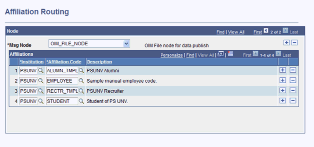
-
Add the Oracle Identity Manager target node.
-
Add the affiliation codes for which you want to receive SCC_CONSTITUENT_SYNC messages.
-
-
Enable affiliation content-based routing as follows:
-
Navigate to PeopleTools, Integration Broker, Integration Setup, and Service Operations.
-
Select service operation SCC_CONSTITUENT_SYNC.
-
Select the Handlers tab.
-
Add a new row with the following details:
Handler name:
ROUTERSENDHDLR.*Type:
OnRouteImplementation:
Application ClassStatus:
Active -
Click Details and enter the following information:
Description:
Affiliations FilterComments:
Affiliations FilterHandler Owner:
SCCPackage Name:
SCC_AFFILIATIONSPath:
HANDLERClass ID:
AffiliationOnRouteSendMethod:
OnRouteSend -
Click OK and Save.
-
Click the Routings tab.
-
Click the link for the routing name that corresponds to the outbound routing from PeopleSoft Campus to the Oracle Identity Manager target node.
-
Click the Parameters tab and add the following details:
Transform Program 1:
SCC_AFL_RICH(this may clear defaults.)The External Alias:
SCC_CONSTITUENT_SYNC.v1Message.Ver into Transform 1:
SCC_CONSTITUENT_DS.v1Message.Ver out of Transforms:
SCC_CONSTITUENT_DS.v1Transform Program: blank
-
Click Save, Return, and then Save.
-
Note:
No matter what you name this handler, the system always automatically renames it to ROUTESENDHDLR. This means that you can only have one OnRoute Send handler for a given service operation.
2.2.3 Installation with Other PeopleSoft Connectors
If you want to use the PeopleSoft Campus connector along with the PeopleSoft Employee Reconciliation and PeopleSoft User Management connectors, then consider the following points:
-
Installing the Campus connector after installing the Employee Reconciliation and PeopleSoft User Management connectors
When installing the Campus connector after the Employee Reconciliation or the User Management connector, you must remove the existing listener (PeopleSoftOIMListener) and deploy the new listener shipped with the Campus connector. This is required because the listener uses the PSFTCommon.jar file, which has been modified to include Campus specific classes.You must also ensure that the PSFTCommon.jar file has been updated in the Oracle Identity Manager database during the connector installation.
-
Installing the Employee Reconciliation or User Management connector after installing the Campus connector
When the Employee Reconciliation or User Management connector is installed after the Campus connector, you must continue to use the existing listener shipped with the Campus connector.
During installation, the PSFTCommon.jar file in the Oracle Identity Manager database would be replaced with the PSFTCommon.jar file shipped with the Employee Reconciliation or User Management connector. To restore the PSFTCommon.jar file shipped with the Campus connector, run the UpdateJars utility shipped with Oracle Identity Manager. This file has some Campus connector specific additions.
2.3 Postinstallation
Postinstallation information is divided across the following sections:
2.3.1 Configuring Oracle Identity Manager
Note:
In an Oracle Identity Manager cluster, you must perform this step on each node of the cluster.
2.3.1.1 Enabling Logging
This section contains the following topics:
2.3.1.1.1 Log Levels and ODL Message Types
Oracle Identity Manager uses Oracle Java Diagnostic Logging (OJDL) for logging. OJDL is based on java.util.logger. To specify the type of event for which you want logging to take place, you can set the log level to one of the following:
-
SEVERE.intValue()+100
This level enables logging of information about fatal errors.
-
SEVERE
This level enables logging of information about errors that may allow Oracle Identity Manager to continue running.
-
WARNING
This level enables logging of information about potentially harmful situations.
-
INFO
This level enables logging of messages that highlight the progress of the application.
-
CONFIG
This level enables logging of information about fine-grained events that are useful for debugging.
-
FINE, FINER, FINEST
These levels enable logging of information about fine-grained events, where FINEST logs information about all events.
These message types are mapped to ODL message type and level combinations as shown in Table 2-4.
Table 2-4 Log Levels and ODL Message Type:Level Combinations
| Java Level | ODL Message Type:Level |
|---|---|
|
SEVERE.intValue()+100 |
INCIDENT_ERROR:1 |
|
SEVERE |
ERROR:1 |
|
WARNING |
WARNING:1 |
|
INFO |
NOTIFICATION:1 |
|
CONFIG |
NOTIFICATION:16 |
|
FINE |
TRACE:1 |
|
FINER |
TRACE:16 |
|
FINEST |
TRACE:32 |
The configuration file for OJDL is logging.xml, which is located at the following path:
DOMAIN_HOME/config/fmwconfig/servers/OIM_SERVER/logging.xml
Here, DOMAIN_HOME and OIM_SEVER are the domain name and server name specified during the installation of Oracle Identity Manager.
2.3.1.1.2 Enabling Logging on Oracle WebLogic Server
To enable logging on Oracle WebLogic Server:
-
Edit the logging.xml file as follows:
-
Add the following blocks in the file:
<log_handler name='psft-cs-handler' level='[LOG_LEVEL]' class='oracle.core.ojdl.logging.ODLHandlerFactory'>
<property name='logreader:' value='off'/>
     <property name='path' value='[FILE_NAME]'/>
     <property name='format' value='ODL-Text'/>
     <property name='useThreadName' value='true'/>
     <property name='locale' value='en'/>
     <property name='maxFileSize' value='5242880'/>
     <property name='maxLogSize' value='52428800'/>
     <property name='encoding' value='UTF-8'/>
   </log_handler>
<logger name="ORACLE.IAM.CONNECTORS.PSFT" level="[LOG_LEVEL]" useParentHandlers="false">
     <handler name="psft-cs-handler"/>
     <handler name="console-handler"/>
   </logger>
<logger name="ORACLE.IAM.CONNECTORS.PSFT.CAMPUS" level="[LOG_LEVEL]" useParentHandlers="false"> <handler name="psft-cs-handler"/> <handler name="console-handler"/> </logger> -
Replace all occurrences of [LOG_LEVEL] with the ODL message type and level combination that you require. Table 2-4 lists the supported message type and level combinations.
Similarly, replace [FILE_NAME] with the full path and name of the log file in which you want log messages to be recorded.
The following blocks show sample values for [LOG_LEVEL] and [FILE_NAME]:
<log_handler name='psft-cs-handler' level='NOTIFICATION:1' class='oracle.core.ojdl.logging.ODLHandlerFactory'>
<property name='logreader:' value='off'/>
     <property name='path' value='F:\MyMachine\middleware\user_projects\domains\base_domain1\servers\oim_server1\logs\oim_server1-diagnostic-1.log'/>
     <property name='format' value='ODL-Text'/>
     <property name='useThreadName' value='true'/>
     <property name='locale' value='en'/>
     <property name='maxFileSize' value='5242880'/>
     <property name='maxLogSize' value='52428800'/>
     <property name='encoding' value='UTF-8'/>
   </log_handler>
<logger name="ORACLE.IAM.CONNECTORS.PSFT" level="NOTIFICATION:1" useParentHandlers="false">
     <handler name="psft-cs-handler"/>
     <handler name="console-handler"/>
   </logger>
<logger name="ORACLE.IAM.CONNECTORS.PSFT.CAMPUS" level="NOTIFICATION:1" useParentHandlers="false"> <handler name="psft-cs-handler"/> <handler name="console-handler"/> </logger>With these sample values, when you use Oracle Identity Manager, all messages generated for this connector that are of a log level equal to or higher than the NOTIFICATION:1 level are recorded in the specified file.
Note:
The logging level for console-handler must be as fine as the level set in the loggers.For example, if the
NOTIFICATION:1level is specified in theORACLE.IAM.CONNECTORS.PSFTlogger, and the console-handler hasERROR:1level, then only logs atERROR:1or coarser levels would be available.
-
-
Save and close the file.
-
Set the following environment variable to redirect the server logs to a file:
For Microsoft Windows:
set WLS_REDIRECT_LOG=FILENAMEFor UNIX:
export WLS_REDIRECT_LOG=FILENAMEReplace FILENAME with the actual name of the file to which you want to redirect the output.
-
Restart the application server.
2.3.1.2 Setting Up the Lookup.PSFT.Campus.Configuration Lookup Definition
Every standard PeopleSoft message has a message-specific configuration defined in the Lookup.PSFT.Campus.Configuration lookup definition. See Lookup.PSFT.Campus.Configuration for more information about this lookup definition.
For example, the mapping for the SCC_CONSTITUENT_SYNC message in this lookup definition is defined as follows:
Code Key: SCC_CONSTITUENT_SYNC
Decode: Lookup.PSFT.Message.SccConstituentSync.Configuration
You can configure the message names, such as SCC_CONSTITUENT_SYNC and SCC_CONSTITUENT_FULLSYNC defined in this lookup definition.
Consider a scenario in which the target system sends the SCC_CONSTITUENT_SYNC.VERSION_3 message. You must change the Code Key value in this lookup definition to implement the message sent by the target system.
To modify or set the Code Key value:
2.3.1.3 Setting Up the Lookup.PSFT.Campus.ExclusionList Lookup Definition
In the Lookup.PSFT.Campus.ExclusionList lookup definition, enter the user IDs of target system accounts for which you do not want to perform reconciliation. See Lookup.PSFT.Campus.ExclusionList for more information about this lookup definition.
2.3.1.4 Configuring SSL
The following sections describe the procedure to configure SSL connectivity between Oracle Identity Manager and the target system:
2.3.1.4.1 Configuring SSL on IBM WebSphere Application Server
You can configure SSL connectivity on IBM WebSphere Application Server with either a self-signed certificate or a CA certificate. Perform the procedure described in one of the following sections:
2.3.1.4.1.1 Configuring SSL on IBM WebSphere Application Server with a Self-Signed Certificate
To configure SSL connectivity between Oracle Identity Manager on IBM WebSphere Application Server and the target system with a self-signed certificate, you must perform the following tasks:
2.3.1.4.1.2 Configuring SSL on IBM WebSphere Application Server with a CA Certificate
To configure SSL connectivity between Oracle Identity Manager on IBM WebSphere Application Server and the target system with a CA certificate, you must perform the following tasks:
-
Log in to the WebSphere Integrated Solutions Console. The URL may be similar to the following:
https://localhost:9043/ibm/console/logon.jsp
-
Click Security, SSL certificate and key management, Related items, Key stores and certificates, NodeDefaultKeyStore.
-
On the Additional Properties tab, click Personal certificate requests.
-
Click New.
-
In the File for certificate request field, enter the full path where the certificate request is to be stored, and a file name. For example:
c:\servercertreq.arm(for a computer running on Microsoft Windows). -
In the Key label field, enter an alias name. You specify the alias name to identify the certificate request in the keystore.
-
In the CN field, enter a value for common name. The common name must be the fully-qualified DNS host name or the name of the computer. The CN of the certificate must match the domain name of your community. For example, if the name of your domain is us.example.com, then the CN of the SSL certificate that you create for your community must also be us.example.com.
-
In the Organization field, enter an organization name.
-
In the Organization unit field, specify the organization unit.
-
In the Locality field, enter the locality.
-
In the State or Province field, enter the state.
-
In the Zip Code field, enter the zip code.
-
From the Country or region list, select the country code.
-
Click Apply and then Save. The certificate request is created in the specified file location in the keystore. This request functions as a temporary placeholder for the signed certificate until you manually receive the certificate in the keystore.
Note:
Keystore tools such as iKeyman and keyTool cannot receive signed certificates that are generated by certificate requests from IBM WebSphere Application Server. Similarly, IBM WebSphere Application Server cannot accept certificates that are generated by certificate requests from other keystore utilities.
-
Send the certification request arm file to a CA for signing.
-
Create a backup of your keystore file. You must create this backup before receiving the CA-signed certificate into the keystore. The default password for the keystore is WebAS. The Integrated Solutions Console contains the path information for the location of the keystore. The path to the NodeDefaultKeyStore is listed in the Integrated Solutions Console as:
was_profile_root\config\cells\cell_name\nodes\node_name\key.p12Now you can receive the CA-signed certificate into the keystore to complete the process of generating a signed certificate for IBM WebSphere Application Server.
-
To receive a signed certificate issued by a CA, perform the following tasks:
-
In the WebSphere Integrated Solutions Console, click Security, SSL certificate and key management, Related items, Key stores and certificates, NodeDefaultKeyStore, and then click Personal Certificates.
-
Click Receive a certificate from a certificate authority.
-
Enter the full path and name of the certificate file.
-
Select the default data type from the list.
-
Click Apply and then Save.
The keystore contains a new personal certificate that is issued by a CA. The SSL configuration is ready to use the new CA-signed personal certificate.
-
2.3.1.4.2 Configuring SSL on Oracle WebLogic Server
You can configure SSL connectivity on Oracle WebLogic Server with either a self-signed certificate or a CA certificate. Perform the procedure described in one of the following sections:
See Also:
2.3.1.4.2.1 Configuring SSL on Oracle WebLogic Server with a Self-Signed Certificate
To configure SSL connectivity between Oracle Identity Manager on Oracle WebLogic Server and the target system with a self-signed certificate, you must perform the following tasks:
2.3.1.4.2.1.2 Configuring Oracle WebLogic Server
After generating and importing the keystore, start Oracle WebLogic Server. To configure Oracle WebLogic Server:
-
Log in to the Oracle WebLogic Server console at
http://localhost:7001/consoleand perform the following:-
Expand the servers node and select the oim server instance.
-
Select the General tab.
-
Select the SSL Listen Port Enabled option.
-
Ensure that a valid port is specified in the SSL Listen Port field. The default port is 7002.
-
Click Apply to save your changes.
-
-
Click the Keystore & SSL tab, and then click Change.
-
From the Keystores list, select Custom identity And Java Standard Trust, and then click Continue.
-
Configure the keystore properties. To do so:
-
In the Custom Identity Key Store File Name column, specify the full path of the keystore generated in Step 1 of Generating Keystore, for example,
c:\temp\keys\keystore.jks. In the Custom Identity Key Store Type column, specify the type of keystore, for example,JKS. In the Custom Identity Key Store Pass Phrase and Confirm Custom Identity Key Store Pass Phrase columns, specify the keystore password. -
Provide the Java standard trust keystore pass phrase and the Confirm Java standard trust keystore pass phrase. The default password is
changeit, unless you change the password. -
Click Continue.
-
-
Specify the private key alias, pass phrase and the confirm pass phrase as the keystore password. Click Continue.
-
Click Finish.
-
Restart Oracle WebLogic Server. If the server starts successfully with the SSL configuration, then lines similar to the following are recorded in the startup log:
<Apr 21, 2008 2:35:43 PM GMT+05:30> <Notice> <WebLogicServer> <BEA-000355> <Thread "ListenThread.Default" listening on port 7001, ip address *.*>
<Apr 21, 2008 2:35:43 PM GMT+05:30> <Notice> <WebLogicServer> <BEA-000355> <Thread "SSLListenThread.Default" listening on port 7002, ip address *.*>
Note:
7002 is the default SSL port for Oracle WebLogic Server.
2.3.1.4.2.2 Configuring SSL on Oracle WebLogic Server with a CA Certificate
To configure SSL connectivity between Oracle Identity Manager on Oracle WebLogic Server and the target system with a CA certificate, you must perform the following tasks:
Note:
Although this is an optional step in the deployment procedure, Oracle strongly recommends that you configure SSL communication between the target system and Oracle Identity Manager.
2.3.1.4.2.2.1 Generating Keystore
The connector requires Certificate Services to be running on the host computer. To generate the keystore:
2.3.1.4.2.2.2 Configuring Oracle WebLogic Server
After creating and importing the keystore to the system, start Oracle WebLogic Server. To configure Oracle WebLogic Server:
-
Log in to the Oracle WebLogic Server console ((http://localhost:7001/console) and perform the following:
-
Expand the server node and select the server instance.
-
Select the General tab.
-
Select the SSL Port Enabled option.
-
Ensure that a valid port is specified in the SSL Listen Port field. The default port is 7002.
-
Click Apply to save your changes.
-
-
Click the Keystore & SSL tab, and click the Change link.
-
From the Keystores list, select Custom Identity And Custom Trust, and then click Continue.
-
Configure the keystore properties. To do so:
-
In the Custom Identity Key Store File Name column, specify the full path of the keystore generated in Step 1 of Generating Keystore, for example,
c:\temp\keys\keystore.jks. In the Custom Identity Key Store Type column, specify the type of keystore, for example,JKS. In the Custom Identity Key Store Pass Phrase and Confirm Custom Identity Key Store Pass Phrase columns, specify the keystore password. -
In the Custom Trust and Custom Trust Key Store File Name column, specify the full path of the keystore generated in Step 1 of Generating Keystore, for example,
c:\temp\keys\rootkeystore.jks. In the Custom Trust Key Store Type column, specify the type of keystore, for example,JKS. In the Custom Trust Key Store Pass Phrase and Confirm Custom Trust Key Store Pass Phrase columns, specify the keystore password. -
Provide the Java standard trust keystore password. The default password is
changeit, unless you change the password. -
Click Continue.
-
-
Specify the alias name and private key password. Click Continue.
-
Click Finish.
-
Restart Oracle WebLogic Server. If the server starts successfully with the SSL configuration, then lines similar to the following are recorded in the startup log:
<Apr 21, 2008 2:35:43 PM GMT+05:30> <Notice> <WebLogicServer> <BEA-000355> <Thread "ListenThread.Default" listening on port 7001, ip address *.*>
<Apr 21, 2008 2:35:43 PM GMT+05:30> <Notice> <WebLogicServer> <BEA-000355> <Thread "SSLListenThread.Default" listening on port 7002, ip address *.*>
Note:
7002 is the default SSL port for Oracle WebLogic Server.
2.3.1.5 Creating an Authorization Policy for Campus ID
Note:
Perform this procedure only if you are using Oracle Identity Manager release prior to 11.1.2.
To create an authorization policy for Campus ID, refer to the instructions given in Oracle Fusion Middleware User's Guide for Oracle Identity Manager. The following instructions are specific to individual steps of the procedure described in Creating an Authorization Policy for User Management. For detailed information on the individual steps, see http://docs.oracle.com/cd/E21764_01/doc.1111/e14316/auth_policy.htm#BGBHGHJI.
-
When you reach Step 3, then:
In the Policy Name field, enter
Campus ID Authorization Policy. -
When you reach Step 4, then:
In the Description field, enter
Campus ID Authorization Policy. -
When you reach Step 7, then:
In the Permissions table, select the following check boxes in the Enable column:
-
Modify User Profile
-
Search User
-
View User Details
Click Edit Attributes.
On the Attribute Settings page, clear all the check boxes and select Campus ID.
-
-
When you reach Step 14 c, then:
From the Available Roles list, select System Administrator, and then click the Move button to move the selected role to the Organizations to Add list.
2.3.1.6 Displaying UDFs in Oracle Identity Manager 11.1.2 or Later
In Oracle Identity Manager release 11.1.2 or later, some user-defined attributes (UDFs), such as Campus ID, that are included in the connector are created only in the backend. If you want to display these attributes as form fields in the Oracle Identity Manager user interface (UI), then you must customize the associated pages on the UI to add the custom form fields. To do so:
2.3.1.7 Localizing Field Labels in UI Forms
Note:
Perform the procedure described in this section only if you are using Oracle Identity Manager release 11.1.2.x or later and you want to localize UI form field labels.
To localize field label that you add to in UI forms:
-
Log in to Oracle Enterprise Manager.
-
In the left pane, expand Application Deployments and then select oracle.iam.console.identity.sysadmin.ear.
-
In the right pane, from the Application Deployment list, select MDS Configuration.
-
On the MDS Configuration page, click Export and save the archive to the local computer.
-
Extract the contents of the archive, and open one of the following files in a text editor:
-
For Oracle Identity Manager 11g Release 2 PS2 (11.1.2.2.0) and later:
SAVED_LOCATION\xliffBundles\oracle\iam\ui\runtime\BizEditorBundle_en.xlf
-
For releases prior to Oracle Identity Manager 11g Release 2 PS2 (11.1.2.2.0):
SAVED_LOCATION\xliffBundles\oracle\iam\ui\runtime\BizEditorBundle.xlf
-
-
Edit the BizEditorBundle.xlf file in the following manner:
-
Search for the following text:
<file source-language="en"
original="/xliffBundles/oracle/iam/ui/runtime/BizEditorBundle.xlf"
datatype="x-oracle-adf">
-
Replace with the following text:
<file source-language="en" target-language="LANG_CODE"
original="/xliffBundles/oracle/iam/ui/runtime/BizEditorBundle.xlf"
datatype="x-oracle-adf">
In this text, replace LANG_CODE with the code of the language that you want to localize the form field labels. The following is a sample value for localizing the form field labels in French:
<file source-language="en" target-language="fr"
original="/xliffBundles/oracle/iam/ui/runtime/BizEditorBundle.xlf"
datatype="x-oracle-adf">
-
Search for the application instance code. This procedure shows a sample edit for PSFTCampus application instance. The original code is:
<trans-unit id="${adfBundle['oracle.adf.businesseditor.model.util.BaseRuntimeResourceBundle']['persdef.sessiondef.oracle.iam.ui.runtime.form.model.user.entity.userEO.UD_AFFLN_CODE__c_description']}"> <source>Affiliation Code</source> <target/> </trans-unit> <trans-unit id="sessiondef.oracle.iam.ui.runtime.form.model.PSFTCampus.entity.PSFTCampusEO.UD_AFFLN_CODE__c_LABEL"> <source>Affiliation Code</source> <target/> </trans-unit> -
Open the resource file from the connector package, for example PSFT-CS_fr.properties and get the value of the attribute from the file, for example, global.udf.UD_AFFLN_CODE=Code d'affiliation.
-
Replace the original code shown in Step 6.c with the following:
<trans-unit id="${adfBundle['oracle.adf.businesseditor.model.util.BaseRuntimeResourceBundle']['persdef.sessiondef.oracle.iam.ui.runtime.form.model.user.entity.userEO.UD_AFFLN_CODE__c_description']}"> <source>Affiliation Code</source> <target>Code d'affiliation</target> </trans-unit> <trans-unit id="sessiondef.oracle.iam.ui.runtime.form.model.PSFTCampus.entity.PSFTCampusEO.UD_AFFLN_CODE__c_LABEL"> <source>Affiliation Code</source> <target>Code d'affiliation</target> </trans-unit> -
Repeat Steps 6.a through 6.d for all attributes of the process form.
-
Save the file as BizEditorBundle_LANG_CODE.xlf. In this file name, replace LANG_CODE with the code of the language to which you are localizing.
Sample file name: BizEditorBundle_fr.xlf.
-
-
Repackage the ZIP file and import it into MDS.
See Also:
Deploying and Undeploying Customizations in Oracle Fusion Middleware Developing and Customizing Applications for Oracle Identity Manager, for more information about exporting and importing metadata files
-
Log out of and log in to Oracle Identity Manager.
2.4 Postcloning Steps
You can clone the PeopleSoft Campus connector by setting new names for some of the objects that comprise the connector. The outcome of the process is a new connector XML file. Most of the connector objects, such as Resource Object, Process Definition, Process Form, IT Resource Type Definition, IT Resource Instances, Lookup Definitions, Adapters, Reconciliation Rules and so on in the new connector XML file have new names.
See Also:
Managing Connector Lifecycle in Oracle Fusion Middleware Administering Oracle Identity Manager for detailed information about cloning connectors and the steps mentioned in this section
After a copy of the connector is created by setting new names for connector objects, some objects might contain the details of the old connector objects. Therefore, you must modify the following Oracle Identity Manager objects to replace the base connector artifacts or attribute references with the corresponding cloned artifacts or attributes:
-
Lookup Definition
If the lookup definition contains the old lookup definition details, then you must modify it to provide the new cloned lookup definition names. If the Code Key and Decode values are referring the base connector attribute references, then replace these with new cloned attributes.
-
Scheduled Task
You must replace the base connector resource object name in the scheduled task with the cloned resource object name. If the scheduled task parameter has any data referring to the base connector artifacts or attributes, then these must be replaced with the new cloned connector artifacts or attributes.
-
Localization Properties
You must update the resource bundle of a user locale with new names of the process form attributes for proper translations after cloning the connector. You can modify the properties file of your locale in the resources directory of the connector bundle.
For example, the process form attributes are referenced in the Japanese properties file, Campus_ja.properties, as
global.udf.UD_CAMPUS_ALIASNAME.During cloning, if you change the process form name fromUD_CAMPUStoUD_CAMPUS1,then you must update the process form attributes toglobal.udf.UD_CAMPUS1_ALIASNAME.
