| StorageTek SL500 Systems Assurance Guide E21060-07 |
|


 Previous |
 Next |
The SL500 library is a modular system that allows the customer to select the required capacity. This chapter outlines the key capacity options of the library.
The SL500 library includes the Capacity on Demand feature, which separates physical capacity from activated capacity. Capacity on Demand allows a client to incrementally pay for and activate desired capacity. As the client's storage needs grow, the client can add modules and activate the necessary capacity.
To expand capacity within an already purchased module, the client only needs to purchase and install an activation file for the new capacity, and then restart the library.
|
Note: Starting with SL500 firmware version 1300 and SLConsole version FRS_4.00, storage capacity upgrades must be installed through the SL500 activation utility. This feature controls cartridge storage cells only. All installed tape drives are available by default. All cells in CAPs configured for enter and eject operations are available if the module containing the CAP has any activated storage cells. |
Important features and restrictions of Capacity on Demand are:
Physical capacity versus Active capacity
Only activated storage cells can be used for tape cartridge storage. Inactivated cells cannot be used for cartridge storage, nor can they be accessed by any hosts.
LTO-only capacity versus Mixed-media capacity
Do not mix LTO and mixed-media arrays and magazines within the same library.
The minimum capacity is 30 storage cells for LTO-only libraries, and 24 storage cells for mixed-media libraries.
The capacity activation increments differ between the two drive types (see below).
Capacity activation is incremental
Full Base - For LTO only, the full base capacity is Base 30-50, which enables the additional 20 slots in the Base Module. For mixed media, the full base capacity is Base 24-42, which enables 18 additional slots.
FullCEM –Enables all storage cells in a cartridge expansion module (CEM).
1/3 DEM –Enables one-third of the storage cells in a DEM. For two-thirds of a DEM, you would install two 1/3 DEM files. For a full DEM, you would install three 1/3 DEMs
Hardware activation files are required
These files activate capacity within the library. See "Hardware Activation Files" for more details on how to download and install these files.
The order that capacity activation files are installed is not significant (that is, it does not need to match the order of the modules in the SL500 frame).
After installing additional capacity, you must restart the library. Once verified by the library controller, the additional storage cells are available for use.
Storage capacity is cumulative
Total capacity is equal to the sum of the capacities specified in each activation file installed on the library.
All storage cells must be contiguous
Gaps in activated capacity are unsupported.
You can begin adding capacity to a module only if the module directly above it is at full capacity. A FullBase capacity base unit is required, either from the initial order or with the upgrade conversion bill, before an expansion module can be added.
Deleting a Capacity file for a module in the middle of a library causes the modules below it to be unavailable. Any partitioning definitions affected will need to be re-done to account for the deleted slots.
|
Note: CEMs should be placed at the bottom of any SL500 configuration. |
Capacity of the last module versus capacity with a module below
The robot cannot access the bottom of the last module due to space constraints. However, when a new module is added below, the bottom of the module becomes accessible. A module type with any module below will have more capacity than when it is placed as the last module. (For clarification refer to "Capacity Values - LTO Only" and "Capacity Values - Mixed Media".)
When active storage capacity changes, the library controller notifies all affected hosts according to their interface requirements. SCSI hosts are notified by a ”Mode Parameters Changed” unit attention. The host must re-audit the library to discover the configuration changes. Customers must consult the appropriate tape management software documentation for detailed procedures and commands.
Customers can purchase additional capacity in the following increments:
Full Base - Referred to as Base 30-50, which enables the additional 20 slots in the Base Module.
FullCEM –Enables all storage cells in a cartridge expansion module (CEM).
1/3 DEM –Enables one-third of the storage cells in a DEM. If the DEM is the last module, the first two 1/3 files add 26 slots each and the third adds 25 slots. If there is a module below, increments are 28, 28, and 28.
|
Note: Do not install an EZ DEM below an original CEM. This is not physically allowed. |
Purchasing and activating LTO slot capacity is covered in Chapter 7, "Ordering".
Table 2-1 and Table 2-2 assume:
There are no reserved cells.
The CAP is set to I/O.
If DEMs and CEMs are installed in the same library, the DEMs are above all of the CEMs (this is the preferred configuration).
Table 2-1 LTO-only Capacity Rules
| Description | Physical Capacity | Active Capacity Value Installed |
|---|---|---|
|
Base Module only (shipped standard) |
30 |
LimitedBase |
|
as last module |
50 |
FullBase (Base 30-50) |
|
with any module below |
66 |
FullBase (Base 30-50) |
|
Adding a DEM as the last module |
77 |
1/3 DEM (in increments of 26, 26, 25) |
|
Adding a DEM with any module below |
84 |
1/3 DEM (in increments of 28, 28, 28) |
|
Adding a CEM after a DEM or Base as the last module |
104 |
FullCEM |
|
Adding a CEM after a DEM or Base with any module below |
114 |
FullCEM |
|
Adding a CEM after CEM as the last module |
110 |
FullCEM |
|
Adding a CEM after CEM with any module below |
120 |
FullCEM |
The following table depicts the capacity of a sample LTO-only library with a base module, a DEM, and a CEM.
Table 2-2 LTO-only Capacity Example
Your software might conflict with the following numbering information. Refer to your software publication for unique information.
If the reserved slots are configured as storage slots, the numbering starts there. You may also configure the CAP slots as storage slots.
For firmware numbering four integers represent the cartridge and tape drive slots, as viewed from the front of the library.
The numbering scheme uses the 1) library, 2) module, 3) row and 4) column scheme.
Library number (always 0)
Library module number 1 (top of rack) through 5 (bottom of rack)
Row number 1 through 9 (base module) or 1 through 12 (expansion module)
Column number 1 through 9 for base module and drive expansion module, 1 through 11 for cartridge expansion module
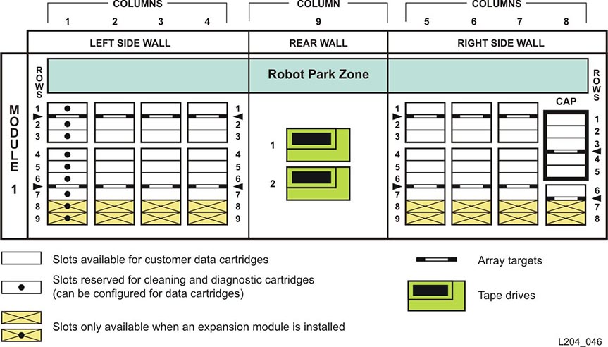
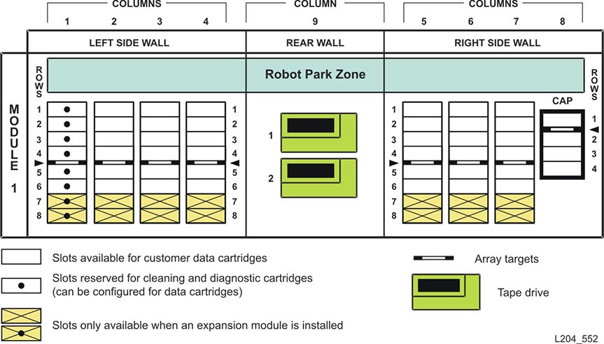
Figure 2-1 shows an LTO-only library with only a base module.
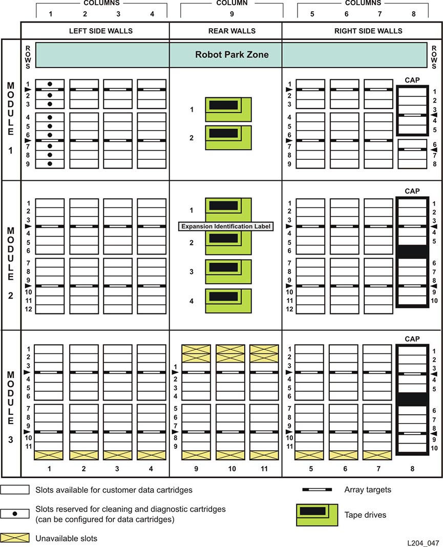
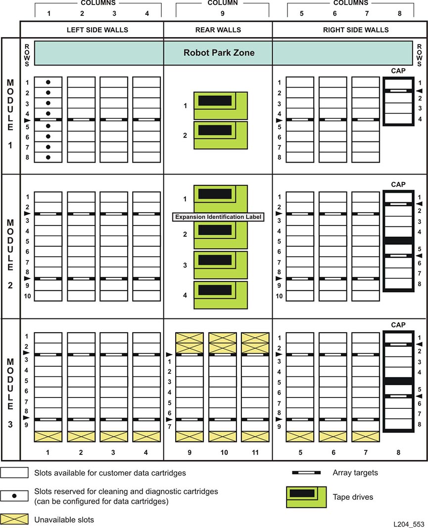
Figure 2-2 shows an LTO-only library with a base module that has nine reserved slots, one drive expansion module, and one cartridge expansion module.
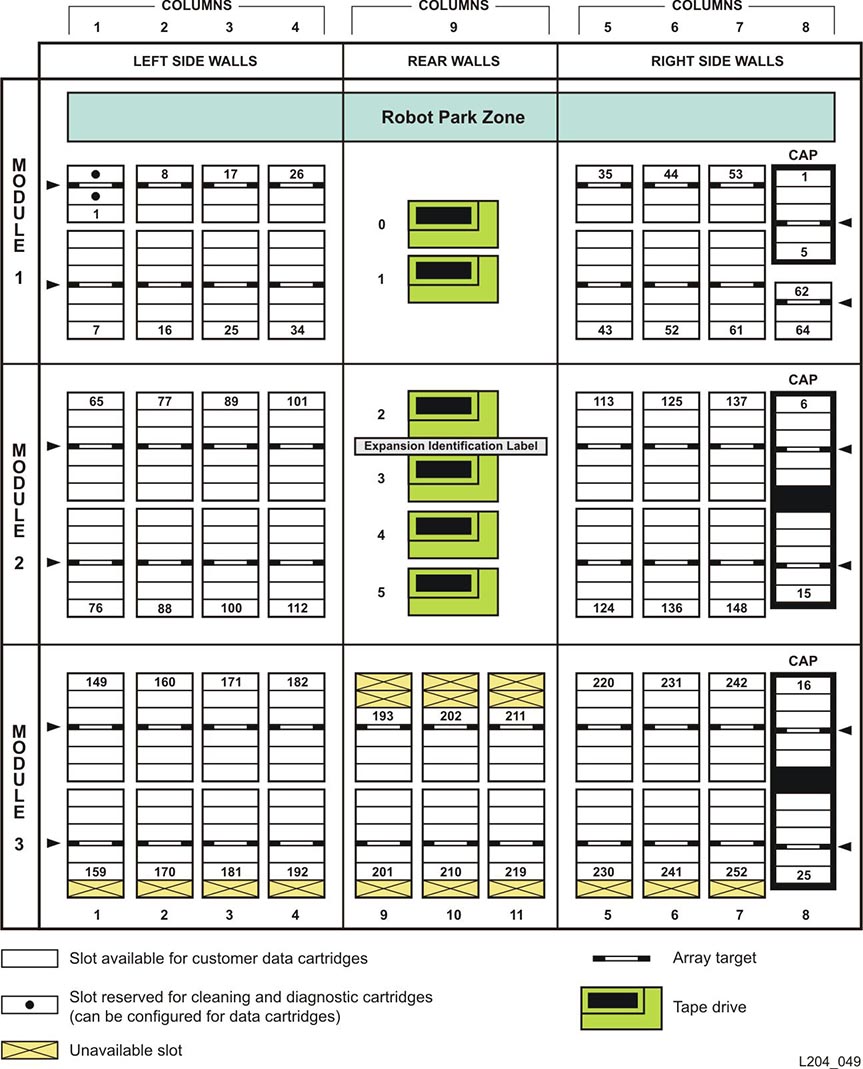
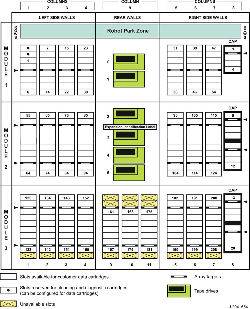
Figure 2-3 shows a library with a base module that has two reserved slots, one drive expansion module, and one cartridge expansion module. The storage slot numbering begins with the first slot after the reserved slots in column 1. The figure shows two reserved slots, but there could be more. If the reserved slots are configured as storage slots, the top slot (row 1) would be 1.
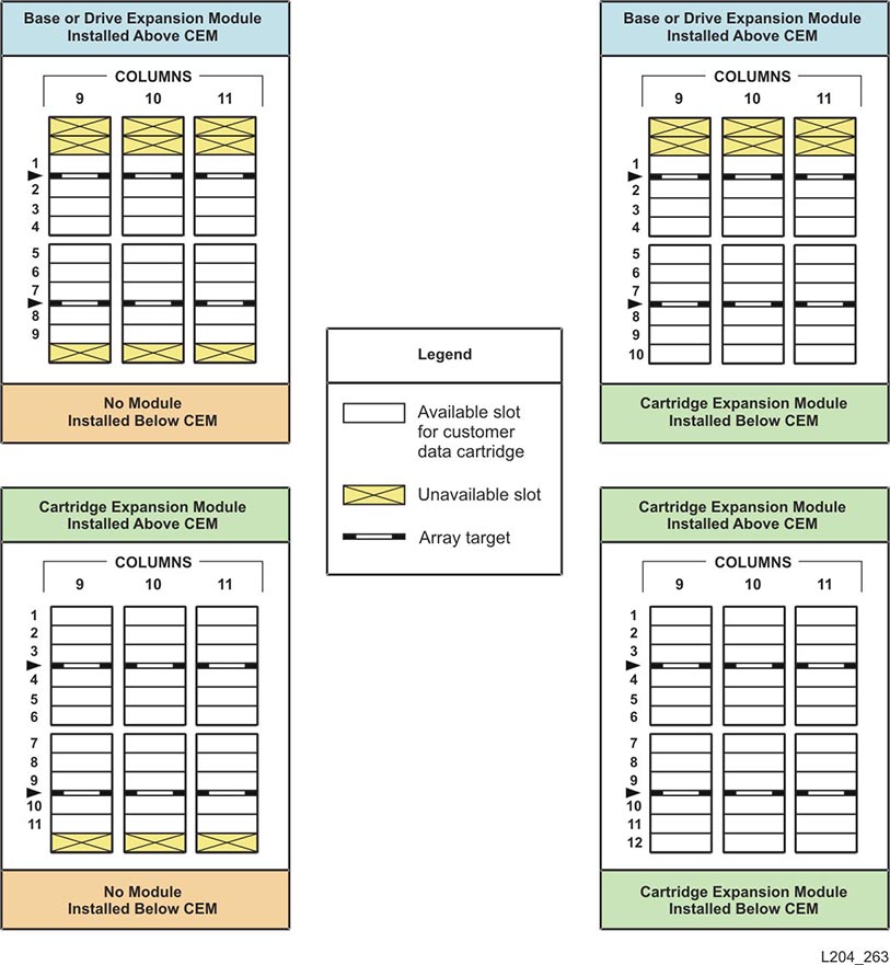
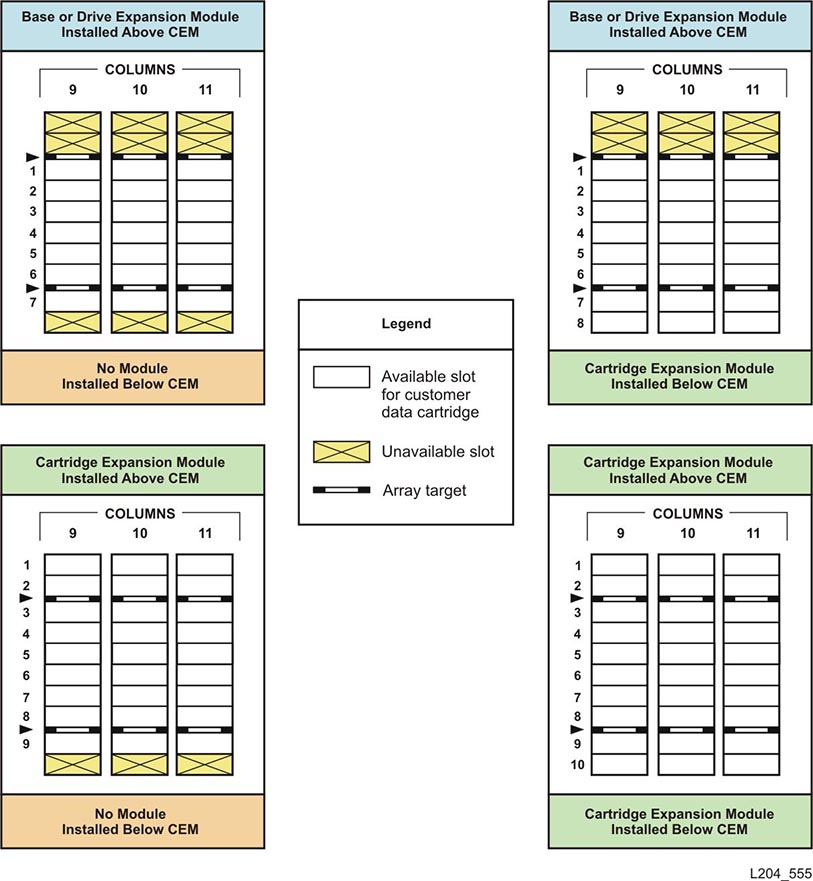
Figure 2-4 shows the slot capacity of a cartridge expansion module according to which type of module is installed above and below it.
|
Caution: Firmware problems: Do not mix LTO and mixed-media arrays and magazines within the same library. If expansion modules are added, the new modules must have the same type arrays as the existing modules. |
Customers can purchase additional capacity in the following increments:
Full Base - Referred to as Base 24-42, which enables the additional 18 slots in the Base Module.
FullCEM –Enables all storage cells in a cartridge expansion module (CEM).
1/3 DEM –Enables one-third of the storage cells in a DEM. If the DEM is the last module, slot counts increment by 21. If there is a module below, the first 1/3 files add 24 slots and last two add 23 slots each.
|
Note: Do not install an EZ DEM below an original CEM. This is not physically allowed. |
Purchasing and activating mixed media slot capacity is covered in Chapter 7, "Ordering".
Table 2-3 and Table 2-4 assume:
There are no reserved cells.
The CAP is set to I/O.
If DEMs and CEMs are installed in the same library, the DEMs are above all of the CEMs (this is the preferred configuration).
Table 2-3 Mixed Media Library Capacity Rules
| Description | Physical Capacity | Active Capacity Value Installed |
|---|---|---|
|
Base Module only (shipped standard) |
24 |
LimitedBase |
|
as the last module |
42 |
FullBase (Base 24-42) |
|
with any module below |
56 |
FullBase (Base 24-42) |
|
Adding a DEM as the last module |
63 |
1/3 DEM (in increments of 21, 21, 21) |
|
Adding a DEM with any module below |
70 |
1/3 DEM (in increments of 24, 23, 23) |
|
Adding a CEM after a DEM or Base Module as the last module |
84 |
FullCEM |
|
Adding a CEM after a DEM or Base Module with any module below |
94 |
FullCEM |
|
Adding a CEM after a CEM as the last module |
90 |
FullCEM |
|
Adding a CEM after a CEM with any module below |
100 |
FullCEM |
The following table depicts the capacity for a sample mixed-media library with a base module, three DEMs, and a CEM.
Table 2-4 Mixed Media Library Capacity Example
| Module | Value | Sequence Number | Additional Slots* | Library Total Count |
|---|---|---|---|---|
|
Base Module (as shipped) |
Shipped standard |
-- |
24 |
24 |
|
Base Module (full capacity) |
Base 24-42 |
100 |
+18 |
42 |
|
Drive Expansion Module |
Additional from Base Module above |
+14 |
56 |
|
|
Drive Expansion Module (with first 1/3 DEM) |
1/3 DEM (increments of 21, 21, 21) |
101 |
+21 |
77 |
|
Drive Expansion Module (with second 1/3 DEM) |
1/3 DEM (increments of 21, 21, 21) |
102 |
+21 |
98 |
|
Drive Expansion Module (with third 1/3 DEM) |
1/3 DEM (increments of 21, 21, 21) |
103 |
+21 |
119 |
|
Drive Expansion Module |
Additional from DEM above |
+7 |
126 |
|
|
Drive Expansion Module (with first 1/3 DEM) |
1/3 DEM (increments of 21, 21, 21) |
104 |
+21 |
147 |
|
Drive Expansion Module (with second 1/3 DEM) |
1/3 DEM (increments of 21, 21, 21) |
105 |
+21 |
168 |
|
Drive Expansion Module (with third 1/3 DEM) |
1/3 DEM (increments of 21, 21, 21) |
106 |
+21 |
189 |
|
Drive Expansion Module |
Additional from DEM above |
+7 |
196 |
|
|
Drive Expansion Module (with first 1/3 DEM) |
1/3 DEM (increments of 21, 21, 21) |
107 |
+21 |
217 |
|
Drive Expansion Module (with second 1/3 DEM) |
1/3 DEM (increments of 21, 21, 21) |
108 |
+21 |
238 |
|
Drive Expansion Module (with third 1/3 DEM) |
1/3 DEM (increments of 21, 21, 21) |
109 |
+21 |
259 |
|
Cartridge Expansion Module |
Additional from DEM above |
+7 |
266 |
|
|
Cartridge Expansion Module (as last module) |
FullCEM |
110 |
+84 |
350 |
The following figures show cartridge slot and tape drive locations for various configurations of the mixed-media SL500 library.
Figure 2-5 shows an mixed-media library with only a base module.