C Library Addressing Reference
Note:
Left and right are in reference to viewing the library from the CAP-side (front) unless otherwise specified.Translating a Slot Address Between HLI and Library Format using SLC
You can use SLC to translate between an internal library address (Library, Rail, Column, Side, Row) and an HLI address (LSM, panel, row, column) used by ACSLS and ELS.
-
In SLC, select Tools > Diagnostics. Select the Library in the device tree.
-
Click the Search tab.
-
Select Location.
-
Select the search criteria from the drop-down list, and enter the address (wildcards are invalid).
-
From the Requester drop-down list, select hli0 if you entered an HLI addresses or select default if you entered an internal library address.
-
Click Search.
-
If you entered an HLI address, the internal library address displays in the Address column of the search results. If you entered an internal library address, click . . . to view the HLI address.
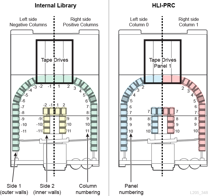
Comparison of Addressing Schemes
-
Internal Library Addressing Scheme (Library, Rail, Column, Side, Row) — used by the firmware and internal communications to represent all devices and locations within the library.
-
Begins at 1 and uses negative numbers.
-
Column indicates the horizontal location in the library
-
Outer wall row numbering is 1 to 13, and inner wall numbering is 1 to 14.
-
-
HLI-PRC Addressing Scheme (LSM, Panel, Row, and Column) — used by HLI clients, such as ACSLS and ELS, to represent library locations and components.
-
Begins with 0 and uses only positive numbers.
-
Column indicates the left or right side of the library
-
Outer wall row numbering is 0 to 12, and inner wall numbering is 13 to 26.
-
-
Physical Hardware Numbering for Tape Drives — identifies the drive slot locations assigned by the HBC card.
Understanding Structural Elements Used in Addressing
-
Each side of the library (left/right) has an inner wall and an outer wall.
-
14-slot arrays on the inner wall
-
13-slot arrays on the outer walls
-
8-slot arrays above the pass-thru port
-
8-slot arrays under the stop brackets for the service safety door
-
4-slot arrays on the elevators and pass-thru ports
-
3-slot arrays at the ends of each rail
-
12-slot arrays for bulk CAP magazine
Each library has four robotic rails. For HLI addressing, each of these rails is considered a library storage module (LSM).
Columns (equivalent to panels in HLI-PRC addressing) refer to the horizontal location of a component in the library (similar to the columns in a spreadsheet). Special columns include:
-
Corners because there is no inner wall
-
Pass-thru ports because the top six slots are inaccessible because of the PTPs
-
Pass-thru port panels because the top cartridge slot (under the port) is reserved as a redundant robotics drop-off slot (two for each rail, one on each side)
Internal Library Addressing Scheme
Internal Library Addressing Overview
Internal library addressing designates location using Library, Rail, Column, Side, Row (L,R,C,S,W).
-
Library — the number of the library within a library complex (always 1 for a single library)
-
Rail — robotic rails numbered top down from 1 to 4.
-
Column — the horizontal location of a device or slot. Column numbering begins at the center of the drive bays and increments +1 to the right or -1 to the left as you move toward the front of the library:
-
+1 is just right of the center of the drive bays.
-
-1 is just to the left of center of the drive bays.
-
The first columns containing tape cartridges are +3 and -3.
-
-
Side — indicates the inner and outer wall, left or right robots, or left or right rotational CAP.
-
Outer wall =1, Inner wall =2
-
Left robot =1, Right robot =2 (in non-redundant robotics the side is always 1)
-
Right rotational CAP =1, Left rotational CAP =2 (for Bulk CAPs the side is always 1)
-
-
Row — The vertical location of a device or slot. Rows are consecutively numbered from the top (1) down (to 13 outer wall and 14 inner wall).
Components (such as CAPs, elevators, PTP, and robots) have unique addressing rules:
-
A row value equal to 0 indicates the address is referring to the device, not a slot in the device.
-
The side value may not directly correlate to inner and outer walls.
-
The column value of elevators and CAPs depends on the number of storage expansion modules in the library.
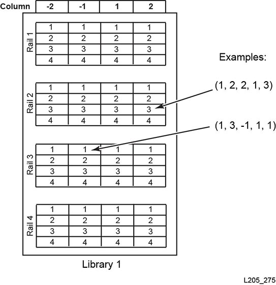
Drive Internal Library Addressing
Drives always have a column value between -2 and 2, a side value of 1, and a row value between 1 and 4.
Rotational CAP Internal Addressing
-
Rail and Row:
-
When numbering the device, the rail value is 2 and the row value is 0.
-
When numbering a specific slot, the rail refers to the rail adjacent to the CAP magazine (can be values 2-4) and the row is the slot in the CAP magazine (can be values 1-13).
-
-
Column: The column value is the number of customer accessible columns plus 3. In a library with no SEMs, there are 11 customer accessible columns, therefore the CAP column value is 14.
-
Side:
-
Right CAP = side value of 1
-
Left CAP = side value of 2
-
Example
For firmware address 1, 3, 22, 2, 10: The library value is 1. The rail is the third from the top (3). The library contains one SEM (19 customer accessible columns plus 3 = 22). The CAP is on the left side (2). The slot is the 10th in the CAP magazine.
Bulk CAP Internal Addressing
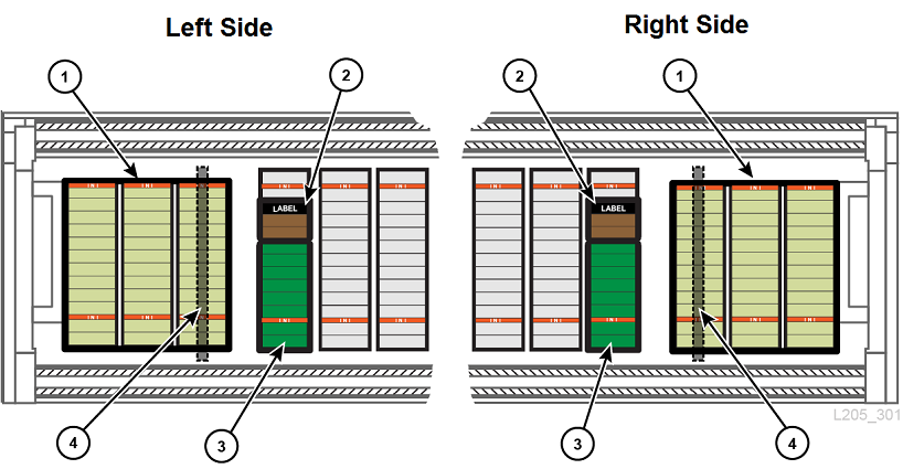
Figure Legend
-
Bulk CAP arrays (12-slots each)
-
Three pack array
-
Reserved system cells
-
Service safety door
Bulk CAP addressing:
-
Rail: The rail number adjacent to the CAP (1 - 4).
-
Row: When numbering the device, the row value is 0. When numbering a specific slot, the row value is the slot in the CAP magazine (1 - 12).
-
Column: The CAP magazines occupy the last three columns in the library. If the library has one SEM, there are 19 customer accessible column. Therefore, the CAP magazines would be in column 20, 21, and 22.
-
Side: Always a value of 1.
Example
For firmware address 1, 3, 22, 2, 10: The library value is 1. The rail is the third from the top (3). The library contains one SEM (19 customer accessible columns, so column 22 is the outer-most column). The CAP is on the left side (2). The slot is the 10th in the CAP magazine.
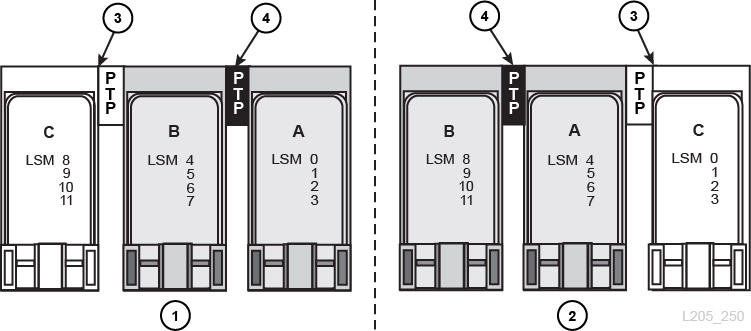
PTP Internal Addressing
-
Rail: The value (1 to 4) refers to the rail adjacent to the PTP.
-
Column: Right PTP = column value of +6, left PTP = column value of -6.
-
Side: The side value is always 1, because the PTPs are on the outer wall.
-
Row:
-
When numbering the device, the row is 0.
-
When numbering a specific slot, the row is the slot in the PTP (1 or 2).
-
Example
For firmware address 1, 2, -6, 1, 0: The library value is 1. The PTP is the second rail from the top (2). It is on the left side (column -6), outer wall (side 1), and the address is referring to the device (0).
Elevator Internal Addressing
-
Rail: The value is always 0, since the elevators do not correspond to a specific rail.
-
Column: The number of customer accessible columns plus 2. In a library with no SEMs, there are 11 customer accessible columns, therefore the elevator column value is 13.
-
Side: The value is always 2 because the elevators are on the inner wall.
-
Row:
-
When numbering the device, the row is 0.
-
When numbering a specific slot, the row is the slot in the elevator (1-4).
-
Example
For firmware address 1, 0, 21, 2, 4: The library value is 1. The elevators span all rails (0). The library contains one SEM (19 customer accessible columns plus 2 = 21). The elevator is on the inner wall (side 2), and the address is referring to the fourth slot in the elevator.
Robot Internal Addressing
-
Rail: The value (1 to 4) refers to the rail the robot is on.
-
Column: The value is always 0.
-
Side:
-
If there is only one robot per rail, the value is always 1.
-
For redundant robotics, the left robot = 1, and the right robot = 2.
-
-
Row:
-
When numbering the device, the row is 0.
-
When numbering the specific slot, the row is the slot value (1).
-
Example
For firmware address 1, 1, 0, 2, 0: The library value is 1. The robot is on the top rail (1). The robot spans all columns (0). It is the right robot in a redundant robotics system (2), and the address is referring to the device (0).
HLI-PRC Addressing Scheme
HLI-PRC Addressing Scheme Overview
HLI-PRC addressing begins with 0, uses only positive numbers, and has four parameters: LSM, Panel, Row, and Column.
-
LSM: Each rail is considered a separate library storage module (LSM). LSMs are numbered 0 to 3 (from the top down).
The libraries in a complex are identified by LSM (see "Library Complex LSM Numbering").
-
Panel: Indicates the horizontal position in the library. Panels span across the width of the library to include both sides (left and right) and both walls (inner and outer) for each LSM. Panel 1 = Drives. Panel 2 to n = Storage slots
Table C-1 Panel Numbering for Various Library Configurations
Configuration Panel Numbering Base Library
RIM (2-7)
CIM (8-10)
One Expansion Module
RIM (2-7)
SEM (8-15)
CIM (16-18)
Two Expansion Modules
RIM (2-7)
SEM (8-15)
SEM (16-23)
CIM (24-26)
Five Expansion Modules
RIM (2-7)
SEM (8-15)
SEM (16-23)
SEM (24-31)
SEM (32-39)
SEM (40-47)
CIM (48-50)
-
Row: Is the vertical location of a tape cartridge and are consecutively numbered from the top down. Outer walls = 0 to12. Inner walls = 13 to 26.
-
Column: Indicates the left or right side of the library (as viewed from the front). Left = 0. Right = 1.
Library Complex LSM Numbering
In a library complex, the LSM number increases sequentially with each additional library. The LSM numbering continues with the following pattern for up to ten libraries:
-
Library 1: LSM 0 to 3
-
Library 2: LSM 4 to 7
-
Library 3: LSM 8 to 11
When adding an additional library to a complex, you should add libraries from right to left (viewed from the CAP-side of the library). Expanding left to right re-numbers the LSMs requiring you to reconfigure hosts.
-
Recommended method with the library added to the left which increases the LSM numbering sequentially
-
Disruptive method, which requires a reconfiguration of LSM numbering.
-
New library
-
Pass-thru-port connecting existing libraries
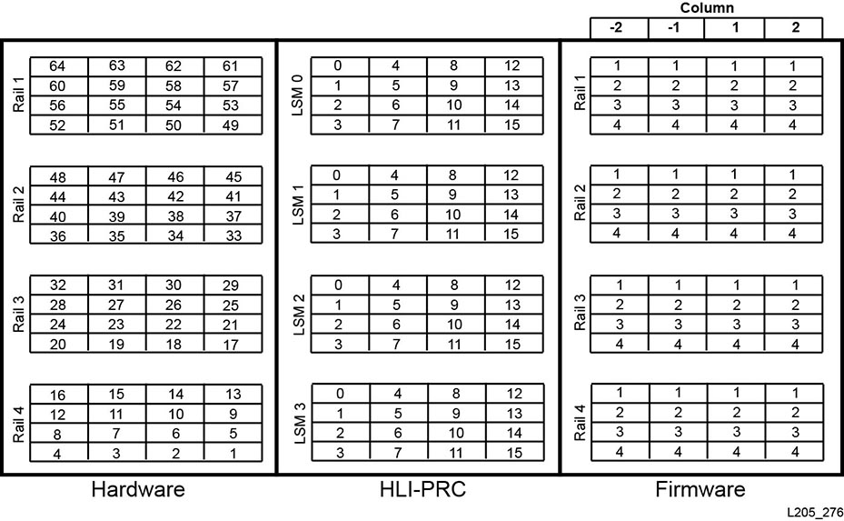
Drive HLI-PRC Addressing
For drives, the panel value is always equal to 1, the column value is always equal to 0, and the row value is between 0 and 15.
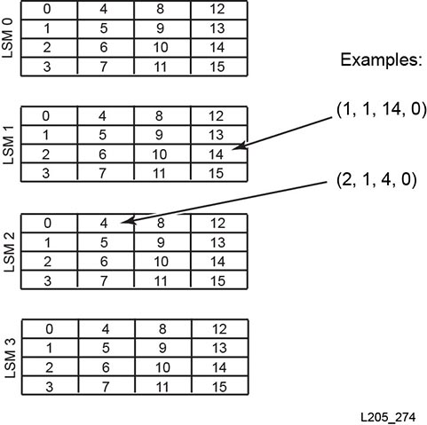
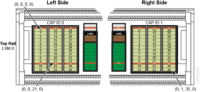
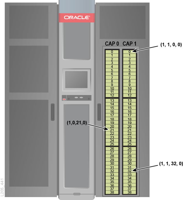
CAP HLI-PRC Addressing
The HLI addressing format for a CAP is (LSM, CAP ID, row, column).
-
LSM - For rotational CAPs, LSM this is always 1. For bulk CAP, LSM corresponds to the rail containing the CAP. Numbered 0 to 3 from top to bottom in a single library. For a complex, see "Library Complex LSM Numbering".
-
CAP ID - Left CAP is 0. Right CAP is 1.
-
Row - Each CAP appears as one continuous column. For rotational CAP, row 0 is at the top and row 38 is at the bottom. For bulk CAP, row 0 is at the top-left corner, and row 35 is at the bottom-right corner of the CAP.
-
Column - Always 0.
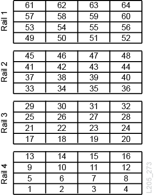
Physical Hardware Numbering for Tape Drives
The HBC card assigns a physical hardware number from 1 to 64.
Reserved Internal IP Addresses
| IP Address | Description |
|---|---|
| 10.0.0.0./24 | Internal device network. |
| 10.0.11.0/24 | ILC network. Host IP addresses based on library identifier. |
| 10.x+2.11.0/24 or
10.(1...253) + 2.11.0/24 |
SDP aliasing. X = complex identifier (1...253). |
| 10.0.4.0/24 | Rail 0 device network. |
| 10.0.3.0/24 | Rail 1 device network. |
| 10.0.2.0/24 | Rail 2 device network. |
| 10.0.1.0/24 | Rail 3 device network. |