| Skip Navigation Links | |
| Exit Print View | |

|
Sun Quad Port GbE PCIe 2.0 ExpressModule, MMF User's Guide |
Understanding the Installation Process
Installation Overview (Oracle Solaris 10)
Installation Overview (Oracle Solaris 11)
Installation Overview (Windows)
Front Panel Connectors and LEDs
Power and Environmental Requirements
Verify the Driver Version (Oracle Solaris 10)
Verify the Driver Version (Oracle Solaris 11)
Remove the Driver (Oracle Solaris OS)
Download and Install the Driver (Linux)
Download and Install the Driver (Windows)
Verify the Installation (Oracle SPARC)
Verify the Installation (Oracle Solaris x86)
Verify the Installation (Linux)
Verify the Installation (Windows)
Create Driver Instance Files (Oracle Solaris 10)
Configure the Network Host Files (Oracle Solaris 10)
Boot Over a GbE Network (Oracle Solaris x86 and Linux)
Install Oracle Solaris 10 Over a Network (Oracle SPARC)
Administering Driver Parameters and Jumbo Frames
Driver Parameters (Oracle Solaris OS)
Set Driver Parameters (Oracle Solaris OS)
Configuring Jumbo Frames (Oracle Solaris OS)
Change the MTU Temporarily (Oracle Solaris 10)
Change the MTU Temporarily (Oracle Solaris 11)
Configure Jumbo Frames (Linux)
Configure Link Aggregations (Oracle Solaris 10)
Display Information About Link Aggregations (Oracle Solaris 10)
Delete Link Aggregations (Oracle Solaris 10)
Configure Static VLANs (Oracle Solaris 10)
Analyze Why the Device Link Is Missing
With multiple VLANs on a single port, a server with a single adapter can have a logical presence on multiple IP subnets. By default, you can define 128 VLANs for each VLAN-aware adapter on your server. However, you can increase this number by changing the system parameters.
If your network does not require multiple VLANs, you can use the default configuration, in which case no further configuration is necessary.
VLANs enable you to split your physical LAN into logical subparts, providing an essential tool for increasing the efficiency and flexibility of your network.
VLANs are commonly used to separate groups of network users into manageable broadcast domains, to create logical segmentation of workgroups, and to enforce security policies among each logical segment. Each defined VLAN behaves as its own separate network, with its traffic and broadcasts isolated from the others, increasing the bandwidth efficiency within each logical group.
Although VLANs are commonly used to create individual broadcast domains or separate IP subnets, it can be useful for a server to have a presence on more than one VLAN simultaneously. Several Oracle Sun products support multiple VLANs on a per-port or per-interface basis, allowing very flexible network configurations.
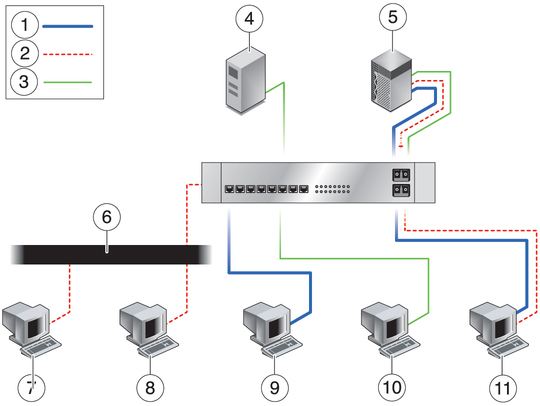
The following figure shows an example network that uses VLANs.
Figure 3 Example VLAN Configuration

Figure Legend
1 VLAN 1
2 VLAN 2
3 VLAN 3
4 Accounting server (VLAN 3)
5 Main server with GbE-tagged adapter (all VLANs)
6 Shared media segment
7 PC 1: Software development (VLAN 2)
8 PC 2: Software development (VLAN 2)
9 PC 3: Engineering (VLAN 1)
10 PC 4: Accounting (VLAN 3)
11 PC 5: Software development and engineering with GbE-tagged adapter (VLAN 1 and VLAN 2)
The example network has the following features:
The physical LAN network consists of a switch, two servers, and five clients. The LAN is logically organized into three different VLANs, each representing a different IP subnet.
VLAN 1 is an IP subnet consisting of the Main Server, Client 3, and Client 5. This VLAN represents an engineering group.
VLAN 2 includes the Main Server, Clients 1 and 2 by means of a shared media segment, and Client 5. This VLAN is a software development group.
VLAN 3 includes the Main Server, the Accounting Server, and Client 4. This VLAN is an accounting group.
The Main Server is a high-use server that must be accessed from all VLANs and IP subnets. The server has a Sun Quad Port GbE PCIe 2.0 ExpressModule, MMF, installed. All three IP subnets are accessed by means of the single physical Ethernet adapter interface. The server is attached to one of the switch's Gigabit Ethernet ports, which is configured for VLANs 1, 2, and 3. Both the Ethernet adapter and the connected switch port have tagging turned on. Because of the tagging VLAN capabilities of both devices, the server is able to communicate on all three IP subnets in this network, but continues to maintain broadcast separation between all of those subnets. The following list describes the components of this network:
The Accounting Server is available to only VLAN 3. The Accounting Server is isolated from all traffic on VLANs 1 and 2. The switch port connected to the server has tagging turned off.
Clients 1 and 2 are attached to a shared media hub that is then connected to the switch. Clients 1 and 2 belong only to VLAN 2. Those clients are logically in the same IP subnet as the Main Server and Client 5. The switch port connected to this segment has tagging turned off.
Client 3 is a member of VLAN 1. This client can communicate only with the Main Server and Client 5. Tagging is not enabled on Client 3's switch port.
Client 4 is a member of VLAN 3. This client can communicate only with the servers. Tagging is not enabled on Client 4's switch port.
Client 5 is a member of both VLANs 1 and 2. This client has a Sun Quad Port GbE PCIe 2.0 ExpressModule, MMF, installed. Client 5 is connected to switch port 10. Both the Ethernet adapter and the switch port are configured for VLANs 1 and 2, and both have tagging enabled.
VLAN tagging must be enabled only on switch ports that:
Create trunk links to other VLAN-aware Ethernet switches.
Are connected to tag-capable end-stations, such as servers or workstations with VLAN-aware Ethernet adapters.