21 Getting Started With Application Modeling Using Diagrams
This chapter describes how to get started modeling your applications, and various application sub-systems, and databases using the diagrams and related diagramming tools and technologies included in Oracle JDeveloper.
This chapter includes the following sections:
21.1 About Modeling with Diagrams
JDeveloper supports four standard UML diagrams types, and four additional diagram types to model and collaborate the software and systems development for your applications. You can use the diagrams in JDeveloper to model your typical business applications, including custom applications.
21.2 Diagram Types
JDeveloper provides New Gallery wizards to create the diagrams for your modeling projects. You can easily create any of these diagrams and related UML and non-uml components using the New Gallery wizards. Select File > New > General > Diagrams from the Menu bar.
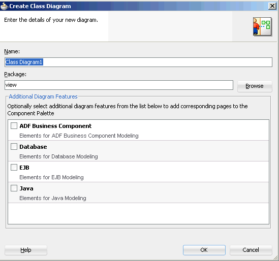
Select your diagram type then double-click, or click OK to start the wizard. The wizard lets you choose the package for your new diagram, as well as select the optional components you want available for that diagram. The component selection feature enables you to choose the diagram-related components you want to show up in the Component Palette while you are editing your diagram. Figure Figure 21-1 shows an example create diagram dialog for a class diagram.
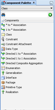
Choose from a variety of different tools, elements, and UML-compliant objects to model your application systems on the diagrams, for example, those available in the Component Palette for a typical class diagram, as shown in Figure 21-2.
21.2.1 UML Diagrams
JDeveloper offers four standard UML diagram types to model your Java classes. You can use all of the standard UML objects, and class and diagram transformation features for UML to easily transform classes to online and offline database objects, or vice-versa. For more information, see Chapter 22, "How to Transform UML and Offline Databases".
Available UML diagram types include the following:
-
Activity Diagram. Model system behavior as coordinated actions. You can use activities to model business processes, such as tasks that achieve specific business goals, like shipping, or order processing.
-
Class Diagram. Model the structure of your system. Create new or inspect the architecture of existing class models, interfaces, attributes, operations, associations, generalizations and interface realizations.
-
Sequence Diagram. Model sequence of event occurrences. Sequence diagrams are organized according to time, and show the calls between the different objects in the sequence. Use the diagram to create or inspect interactions between events, lifelines, messages and combined fragments.
-
Use Case Diagram. Visually model what a system is supposed to do. A use case diagram is a collection of actors, use cases, and their communications.
21.2.2 Business Services Diagrams
You can model your business services and entities and their relationships in your applications using both regular and UML objects. Using JDeveloper transformation features for UML objects, you can transform online or offline database tables to classes, or classes to database tables. All of these objects can be modeled on any of the following four diagrams:
-
Business Components Diagram. Diagram your business component interrelationships, entity classes, interactions, and public interfaces.
-
Database Diagram. Model your online and offline database tables and their relationships. Use transformation features to create a diagram model that represents your database schema, or transform your classes to database tables online or offline.
-
EJB Diagram. Create, edit, and model the entity objects, session and message-driven beans inside a system, and the relationships between them.
-
Java Class Diagram. Model the relationships and the dependencies between Java classes. Use Java Class Diagrams to visually create or inspect objects like interfaces, enums, fields, methods, references, inheritance relationships, and implementation relationships.
21.3 How to Set Paths for a Modeling Project
You can configure the settings of a JDeveloper project to specify the root locations of the package hierarchies for modeled elements available to that project. The model path is configured by default. Change it if you want to include model element files to your model that are stored somewhere else, or to store new model element files somewhere else.
Modeled elements can be shared between projects by adding their file system location to the model path for a project.
To set the model path for a project:
-
Right-click the project whose model path you want to specify.
-
Choose Project Properties.
-
Open the Project Source Paths node and select the Modelers node.
-
In the Model Path area, use Add to enter the file system location for your project's model elements. Note that the order in which file system locations are entered in the Model Path signifies the order in which the folders are searched for a model element. These folders are the 'roots' of the package hierarchies used by a model. The first location specified in the model path is also the location in which new model elements are stored.
-
To complete the setting of the model path, click OK.

