2 Pre-Notification Setup
This chapter contains these topics:
2.1 World Writer Setup
During the Notification process, the system runs the World Writer version that is set up. The World Writer setup is used to select the information and components of the transaction payload (data). The data key for the transaction must be part of the World Writer Selection criteria and must be listed in the correct key order. Also, by using the export parameters for the World Writer, an .xsd conversion file can be supplied that is used to convert the transaction payload into an .xml document if needed.
The .xml document is ultimately sent as the payload for the real time event.
-
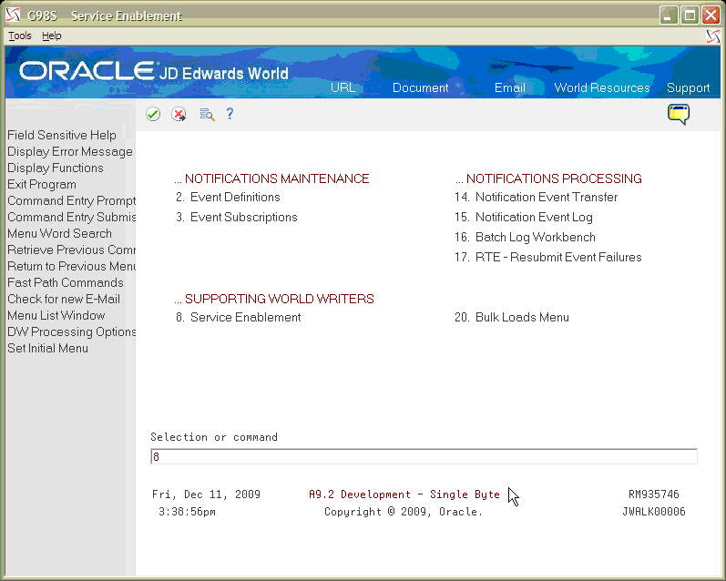
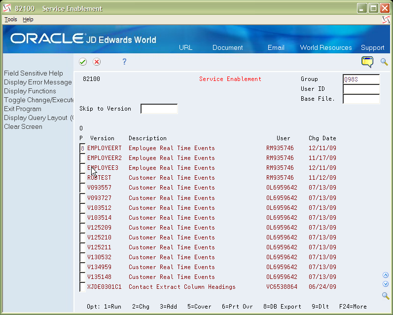
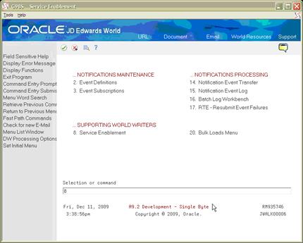
Sign on to the JD Edwards World A9.3 Environment and select the Service Enablement menu (G98S).
-
Select 8, Service Enablement Supporting World Writers. Enter a 3 in the Option field next to a blank line to add a new version.
Figure 2-2 Service Enablement (World Writers) screen
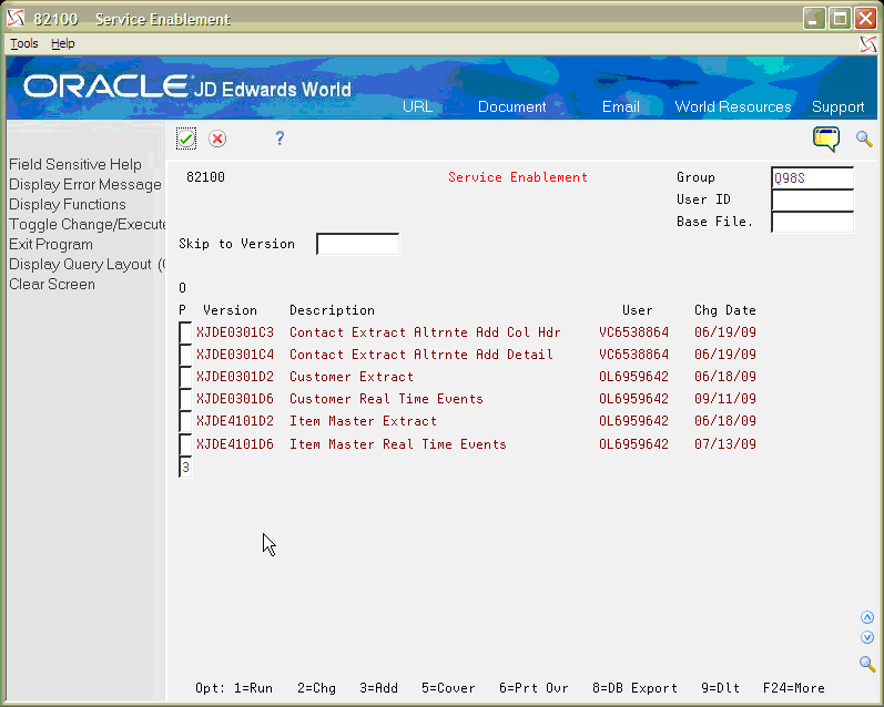
Description of "Figure 2-2 Service Enablement (World Writers) screen"
-
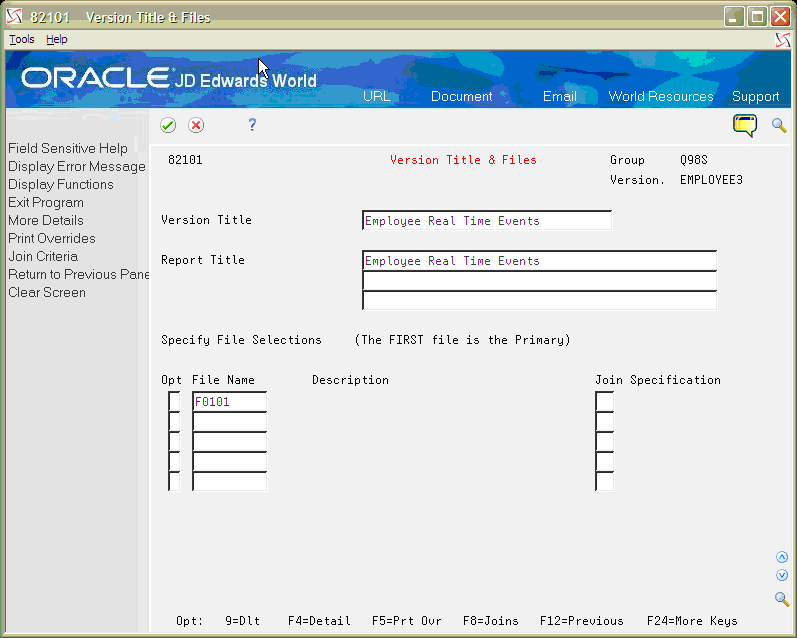
From the Query Version Copy screen, enter EMPLOYEERT for the new version name and Employee Real Time Events for the Version Title. Enter F0101 for the File Name. Press Enter.
-
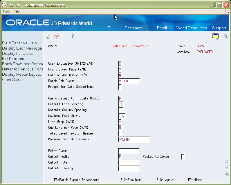
From the Additional Parameters screen, click the check mark button or press Enter.
-
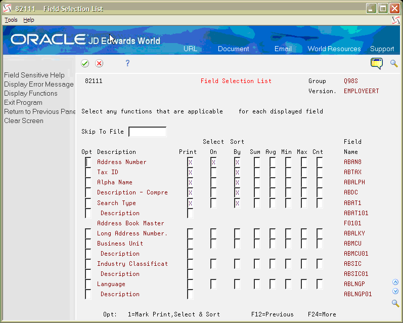
From the Field Selection List screen, enter an X on the Print and Sort By fields for the following Fields in the file:
-
Address Number (ABAN8)
-
Tax ID (ABTAX)
-
Alpha Name (ABALPH)
-
Description - Compressed (ABDC)
-
Search Type (ABAT1)
Enter an X on the Select On field for the Address Number. Press Enter and then exit from the Selective Change Prompt screen.
-
-
On the Service Enablement World Writer screen, enter an 8 in the Option file next to the newly created EMPLOYEERT World Writer version to access the Database Export screen.
Figure 2-6 Service Enablement (EMPLOYEERT) screen
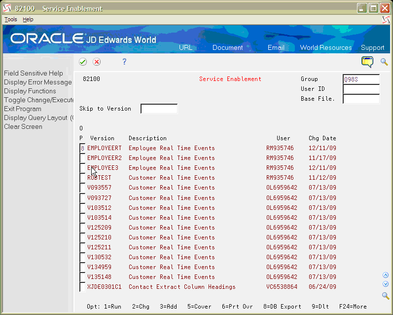
Description of "Figure 2-6 Service Enablement (EMPLOYEERT) screen"
-
From the Database Export Parameters screen, complete the following fields:
Field Explanation Sample Use Case Value Import Export File Import Export File name is the name to be given to the import or export file on the IFS. This must be a valid Windows file name. EmployeeRT.xml IFS Path The string defining the path to the import/export file on the Integrated File System. For Example: /ImportExport/ /home/EmployeeRT Replace Records Tells whether or not to delete and replace or append records to the output file Y Header Detail Join Relationship This option specifies if the joined tables selected for export have a header detail relationship or not. N Enabled Y/N Determines whether the transformation is enabled or not. Y Transformation Template The name of the transformation template that is going to be used to create the .xml file Figure 2-7 Database Export Parameters screen
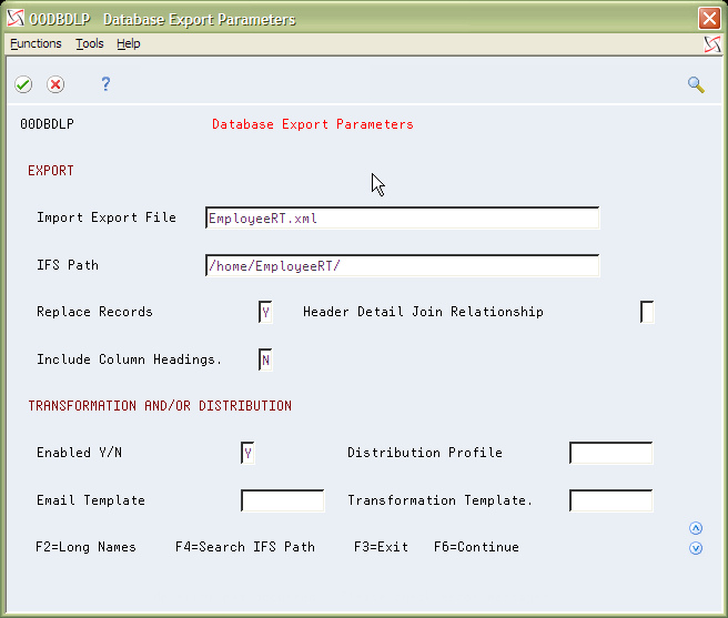
Description of "Figure 2-7 Database Export Parameters screen"
2.2 XSL Transformation Setup
During real time notification processing, data from World tables is gathered through a World Writer report. Using the World Writer export capabilities, the data can be converted into an XML format. When exporting the data through a notification event, typically the World XML format does not conform to what an outside entity is expecting. Using the transformation abilities provided by the World Electronic Document Delivery (EDD) system, the World Writer XML can be converted to an XML file with a different format. To create the pieces that are needed for the transformation process, a separate application is needed to handle the XML related files. An XSL transformation file (.xsl), Extensible Style Sheet, needs to be created to map values from the World generated XML format to the outgoing XML format. Typically, to create an .xsl transformation you need to create a mapping between two XML Schema Definition (.xsd) files. For the World created XML file, the World Writer export functionality can create the .xsd. For the outgoing XML schema, if one is not provided, you can use an XML editor to create the .xsd from a sample .xml file.
For this example, JDeveloper is used to create the XSL transformation file.
-
Sign on to the JD Edwards World A9.3 Environment and select the Service Enablement menu (G98S).
-
Select number 8, Service Enablement supporting World Writers. Enter an 8 next to the EMPLOYEERT version that was created previously to work with the Export parameters.
Figure 2-9 Service Enablement (Export) screen
Description of "Figure 2-9 Service Enablement (Export) screen"
-
From the Database Export Parameters screen, change the Import Export File from EmployeeRT.xml to EmployeeRT.xsd. Then press F6 to continue.
The system creates the XML Schema Definition file for the World generated XML. This file needs to be copied from the IFS directory to the local workstation/PC where the XSL transformation file is created.
Note:
Users can create IFS directories with EBCDIC or ASCII CCSIDs. Directories used for XSL transformations using EDD must be set up with an ASCII CCSID. For more information, see Setting up Import/Export in the JD Edwards World Technical Tools Guide.Figure 2-10 Database Export Parameters screen
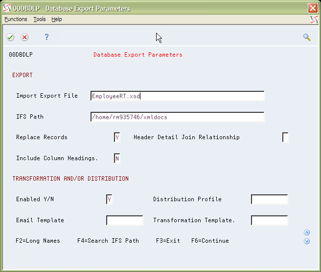
Description of "Figure 2-10 Database Export Parameters screen"
-
Enter an 8 again next to the EMPLOYEERT version. From the Database Export Parameters screen, change the Import Export File back to EmployeeRT.xml. Press Enter and then press F3 to exit.
Figure 2-11 Database Export Parameters (EmployeeRT.xml) screen
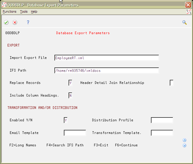
Description of "Figure 2-11 Database Export Parameters (EmployeeRT.xml) screen"
-
A Target schema is needed for the notification. If you do not have a target schema or xml already, you need to create the target schema or xml.
The following schema was created for the Sample Use Case and can be copied and saved as a .xsd to add to the project for use when creating the .xsl mapping file, which is done in the next steps.
<?xml version="1.0" encoding="UTF-8" standalone="yes"?>
<xs:schema xmlns:xs="http://www.w3.org/2001/XMLSchema">
  <xs:element name="Employee">
    <xs:complexType>
      <xs:sequence maxOccurs="unbounded" minOccurs="0">
        <xs:element name="EmployeeInfo">
          <xs:complexType>
            <xs:sequence maxOccurs="unbounded" minOccurs="0">
              <xs:element name="EmployeeName" type="xs:string" maxOccurs="unbounded" minOccurs="0"/>
              <xs:element name="EmployeeID" type="xs:string" maxOccurs="unbounded" minOccurs="0"/>
              <xs:element name="EmployeeSocial" type="xs:string" maxOccurs="unbounded" minOccurs="0"/>
            </xs:sequence>
          </xs:complexType>
        </xs:element>
      </xs:sequence>
    </xs:complexType>
  </xs:element>
</xs:schema>
</xs:sequence>
-
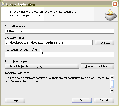
From a local workstation/PC, open JDeveloper 10.1.3.4. In the Application tab (typically in the left hand column), right-click on Applications and select New Application.
Figure 2-12 JDeveloper - New Application screen
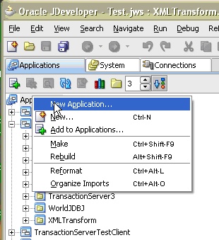
Description of "Figure 2-12 JDeveloper - New Application screen"
-
From the Create Application screen, enter an Application Name and then click OK.
-
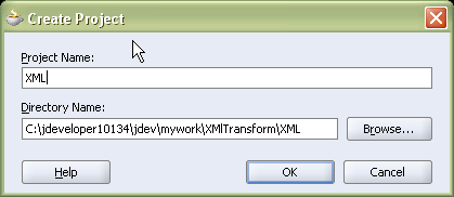
From the Create Project screen, enter the project name and then click OK.
-
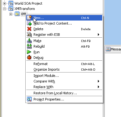
From the main JDeveloper screen, right-click the newly created project and select New.
-
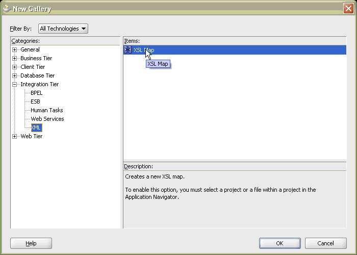
From the New Gallery screen, open the Integration Tier menu and select XML. Select the XSL Map under Items and then click OK.
-
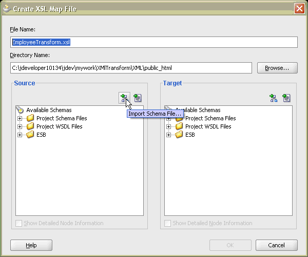
From the Create XSL Map File screen, enter the .xsl file name. Under the Source frame, click the Import Schema File button.
-
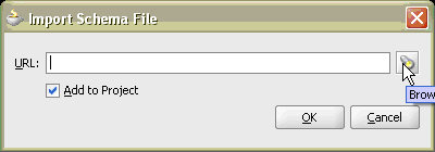
From the Import Schema File screen, click the Browse flashlight button to browse the file directory.
-
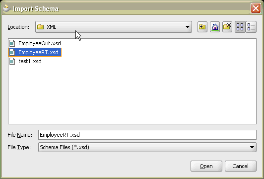
From the Import Schema screen, select the .xsd file that was created in World and copied to the local machine. Select Open.
-
From the Import Schema File screen, check the Add to Project box. Click OK.
Figure 2-20 Import Schema File (Add to Project) screen
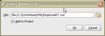
Description of "Figure 2-20 Import Schema File (Add to Project) screen"
-
Repeat steps 11-14 for the Target schema.
If the target schema is already a part of the project, you can select it from the Project Schema Files under the Available Schemas in the Target frame.
-
After the schemas are loaded, from the Create XSL Map File screen, open the schema nodes by selecting the + sign next to each schema. Click each of the nodes and then click OK.
Figure 2-21 Create XSL Map File (Nodes) screen
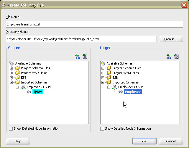
Description of "Figure 2-21 Create XSL Map File (Nodes) screen"
-
From the main JDeveloper screen, the .xsl mapping screen displays in the development frame. Right-click the Source and then select Expand All. Right-click the Target and select Expand All. This allows you to see all the detailed nodes.
Figure 2-22 JDeveloper (.xsl Mapping) screen
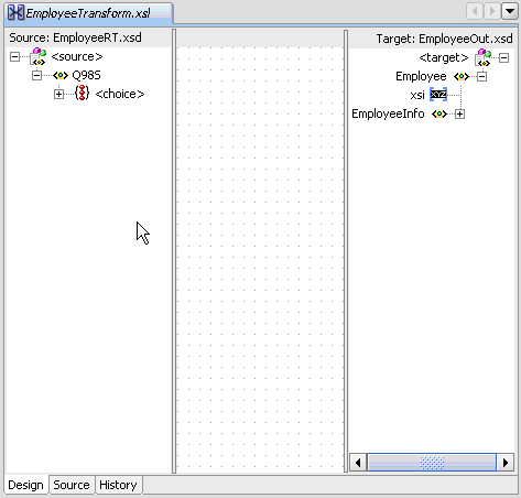
Description of "Figure 2-22 JDeveloper (.xsl Mapping) screen"
-
Left-click the detail elements from the Source schema and, while holding the button down, move the line over to the detail element from the Target schema. Repeat step 18 for all the detail elements that need to be mapped.
Figure 2-23 JDeveloper (.xsl Mapping, Detail) screen
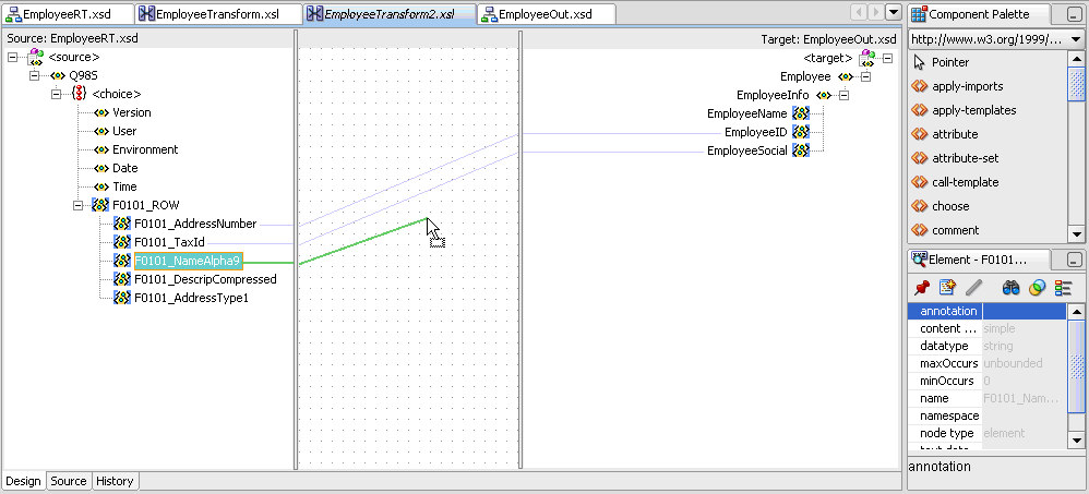
Description of "Figure 2-23 JDeveloper (.xsl Mapping, Detail) screen"
-
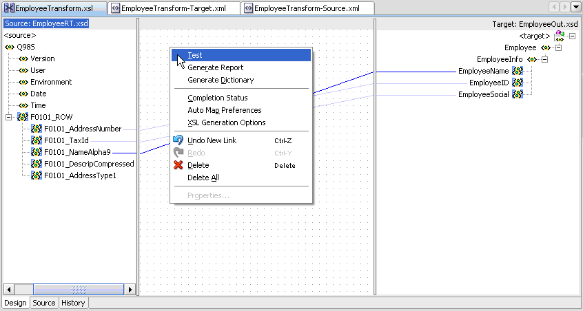
After the mapping is complete, it must look something similar to the following graphic. Make sure to save the .xsl.
Figure 2-24 JDeveloper (.xsl Mapping Complete) screen
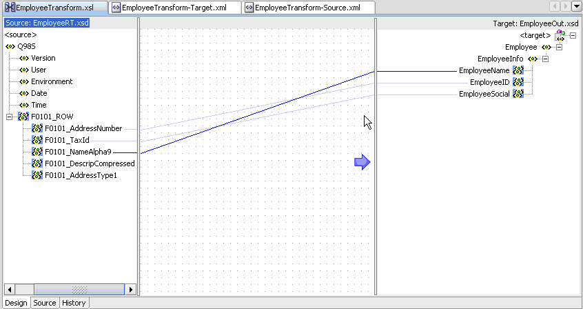
Description of "Figure 2-24 JDeveloper (.xsl Mapping Complete) screen"
-
Right-click the mapping development frame and then select Test.
-
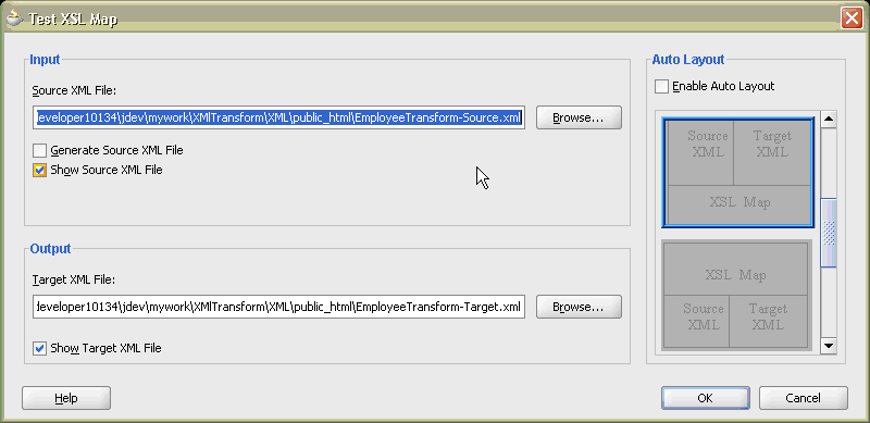
From the Test XSL Map screen, accept the defaults and then click OK.
-
Once the Test is run, you see the Source and Target .xml files displayed in the main JDeveloper screen.
Figure 2-27 JDeveloper (Source and Target .xml) screen
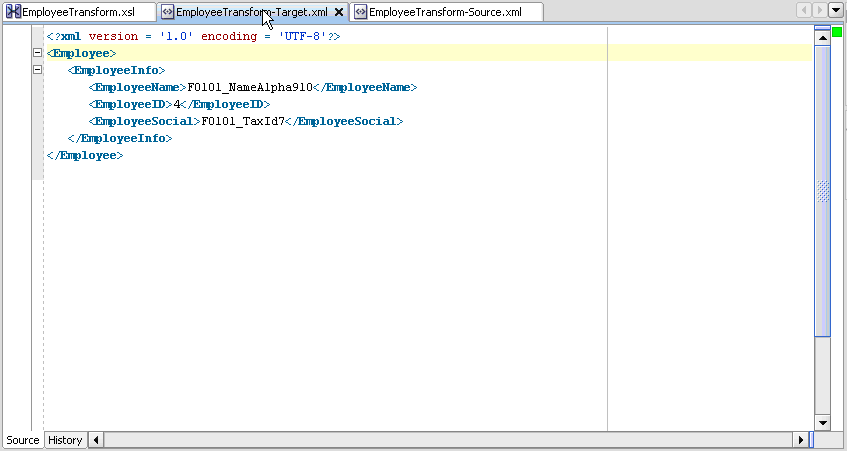
Description of "Figure 2-27 JDeveloper (Source and Target .xml) screen"
-
Copy the .xsl file that was created to the IFS directory where the source EmployeeRT.xsd is located.
2.3 Event Type User Defined Code
An Event Type UDC value needs to be set up for the specific Real Time Event that is going to be processed.
-
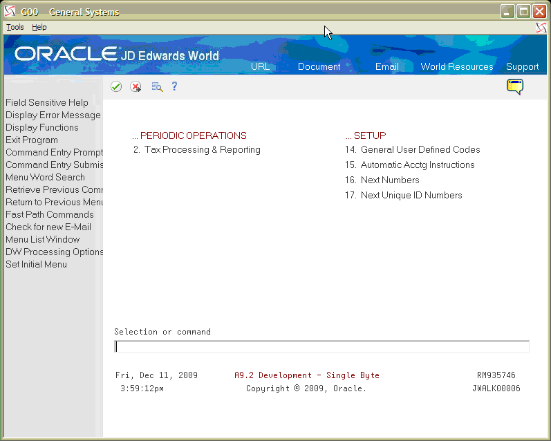
Sign on to the JD Edwards World A9.3 Environment and select the General Systems menu (G00).
-
Select Option 14 for General User Defined Codes.
Figure 2-29 General User Defined Codes screen
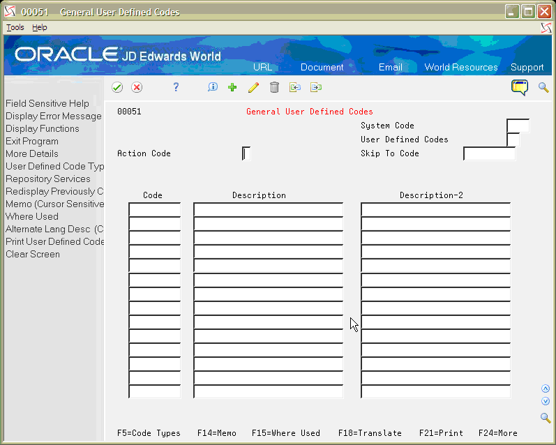
Description of "Figure 2-29 General User Defined Codes screen"
-
Inquire on System Code 98S, User Defined Code ET. Add a new Event Type User Defined Code record for the new event type. For the Sample Use Case, the Event Type entered is EMP1, Employee Real Time Event.
Field Explanation Sample Use Case Value Code Name of the Event Type. EMP1 Description The Description of the Event Type. Employee Real Time Event Figure 2-30 General User Defined Codes (New Event Type) screen
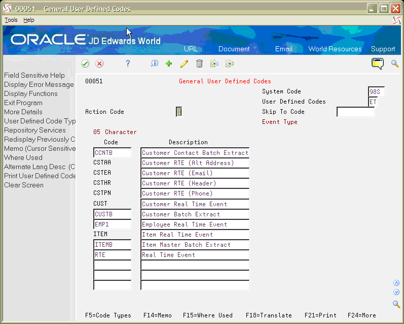
Description of "Figure 2-30 General User Defined Codes (New Event Type) screen"
2.4 Code Changes to X00A1213
You need to make RPG code changes to the X00A1213 to handle the new Event Type created. This procedure helps you make the code changes.
-
Sign on to JD Edwards World A9.3 Environment and add the following code changes in a custom directory:
0129.00 D CUST_PI_RTE     C                   'NTY_000005'
0130.00 D CUST_EI_RTE     C                   'NTY_000006'
0131.00 D CUST_AI_RTE     C                   'NTY_000007'
0132.00 D EMPL_AA_RTE     C                   'EMP_RTE'                    INSERT
0133.00 D*
0134.00 D @OV             S              1    DIM(15)
0135.00 D @NV             S              1    DIM(15)
0136.00 D*
0137.00 D KY0101          DS
0138.00 D  KY0101EVT                     5a
0265.00 C                   When      PSKY = CUST_EI_RTE
0266.00 C                   Exsr      SCustEmlAdd
0267.00 C                   When      PSKY = CUST_AI_RTE
0268.00 C                   Exsr      SCustAltAddAdd
0269.00 C                   When      PSKY = ITEM_RTE
0270.00 C                   Exsr      SItem
0270.01 C                   When      PSKY = EMPL_AA_RTE
0270.02 C                   Exsr      SEmployee
0271.00 C                   Other
0272.00 C                   Move      *Blanks       ETEVDK
0273.00 C                   Endsl
0274.00
0275.00 C                   Endif
1854.00 C Enddo 1855.00 C* 1856.00 C Movea @NV ScrubedValue 1857.00 C* 1858.00 C Endsr 1859.00 ***************************************************************** 1860.00 1861.00 * SUBROUTINE SEmployee - Build Employee notify message. 1862.00 * -------------------------------------------------------------- 1863.00 1864.00 C SEmployee Begsr 1865.00 * ------ ----- 1866.00 * 1867.00 * Set event key equal to the transaction key. In this case the trans 1868.00 * key will be equal to the Address Book ABAN8 1869.00 * 1870.00 C Exsr SCrtEvtSeq 1871.00 1872.00 C Movel TTTRKY ETEVDK 1873.00 C Clear KY0101 1874.00 C Movel EDEVT KY0101EVT 1875.00 C Movel TTTRKY KY0101AN8 1876.00 C EVAL RecCount = 0 1877.00 C Eval ChgTyp = *Blanks 1878.00 C* 1893.00 C/Exec Sql 1894.00 C+ Select Count(BDTCHT) Into :RecCount 1895.00 C+ From F00ACB 1896.00 C+ Where BDTANM = :TTTANM 1897.00 C+ And BDAFLE = 'F0101' 1898.00 C+ And BDTRKY = :TTTRKY 1899.00 C+ And BDTCHT = 'A' 1900.00 C/End-Exec 1901.00 C 1902.00 C If SqlCode = C_SqlOk 1903.00 C And RecCount > 0 1904.00 C Eval KY0101ACTN = '1' 1905.00 C Endif 1910.00 * 1911.00 C* Movel(p) KY0101 ETEVDK 1912.00 C Movel(p) KY0101 PSEVDK 1913.00 C Exsr SInsert 1914.00 1915.00 * Call the Event Transfer Service program 1916.00 1917.00 C Clear Command 1918.00 C 1919.00 C Move *All'0' PSEVSQA 1920.00 C Move PSNBR PSEVSQA 1921.00 C 1922.00 C EVAL Command = 'SBMJOB CMD(CALL PGM(JX98S710) ' + 1923.00 C 'PARM(' + '''' + PSEVSQA + '''' + 1924.00 C ' ' + '''' + PSEVDK + '''' + 1925.00 C ' ' + '''' + '1' + '''' + ' ' + 1926.00 C '''' + ' ' + '''' +'))' + 1927.00 C ' JOB(JX98S710) JOBD(JDEAPPRVL)' 1928.00 C 1929.00 C Call 'QCMDEXC' 81 1930.00 C Parm Command 1931.00 C Parm 500 CommandLength 15 5 1932.00 C* 1933.00 C Endsr 1934.00 ***************************************************************** . -
Once the changes are made, save the program and compile. Add the custom library list to your environment.
2.5 Creating JMS Resources
To receive the outbound notification JMS message from World, create a JMS Topic or Queue and a corresponding connection factory. For the Sample Use Case, a JMS Queue is created on the same Oracle WebLogic Application Server that the World Transaction Server is installed on.
-
Log on to the Weblogic Administration Console with the administrative log on.
Figure 2-31 Weblogic Administration Console screen
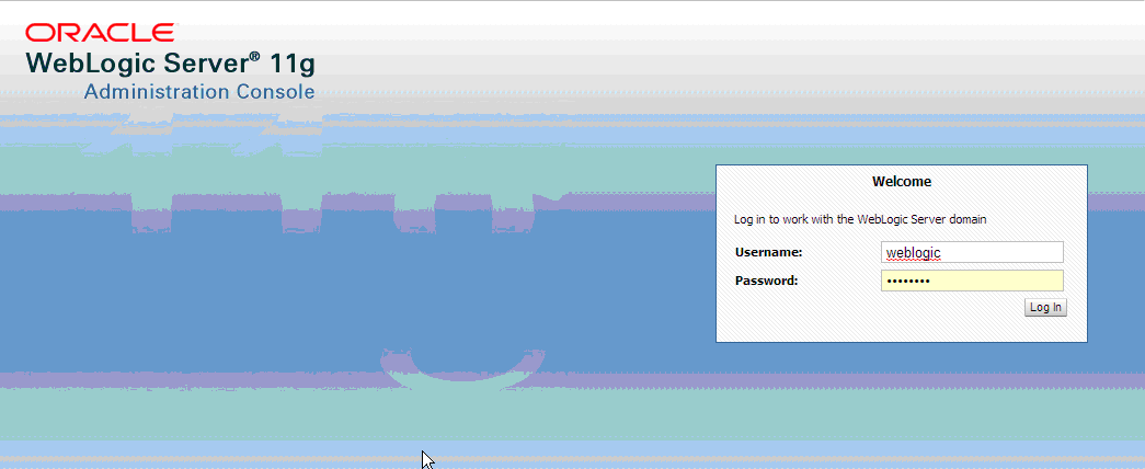
Description of "Figure 2-31 Weblogic Administration Console screen"
-
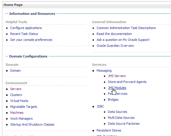
From the Admin Console Home page, select the JMS Modules link under the Services -> Messaging heading.
-
On the JMS Modules screen, select the JMS Module created for the Transaction Server or create a new one.
Figure 2-33 JMS Modules (Transaction Server) screen
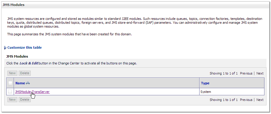
Description of "Figure 2-33 JMS Modules (Transaction Server) screen"
2.5.1 Connection Factory
Use the following steps to create the Connection Factory:
-
Employee Connection Factory
-
Name: EmployeeConnectionFactory
-
JNDI Name: jms/WorldConnectionFactory
-
On the Settings for JMS Module screens, click Lock and Edit and then click New.
Figure 2-34 JMS Module (Lock and Edit) screen
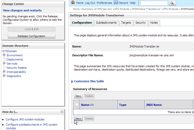
Description of "Figure 2-34 JMS Module (Lock and Edit) screen"
-
On the Create a New MS System Module Resource screen, select the Connection Factory radio button and then click Next.
Figure 2-35 Create a New JMS Module Resource screen
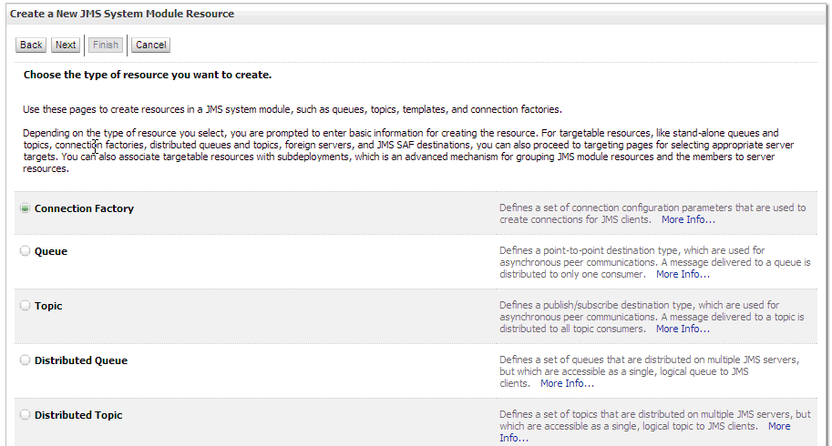
Description of "Figure 2-35 Create a New JMS Module Resource screen"
-
On the Connection Factory screen, enter the connection factory name and JNDI name exactly as it is above.
Figure 2-36 Connection Factory Properties screen
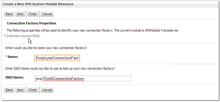
Description of "Figure 2-36 Connection Factory Properties screen"
-
On the Create a New JMS System Module Resource Targeting screen, click Advanced Targeting.
Figure 2-37 Create a New JMS System Module Resource (Advanced Targeting) screen
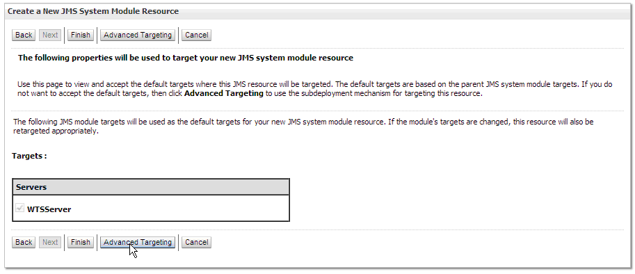
Description of "Figure 2-37 Create a New JMS System Module Resource (Advanced Targeting) screen"
-
On the Create a New JMS System Module Resource Advanced Targeting screen, either click Create a New Subdeployment if a subdeployment is not already created or select the subdeployment from the drop down list if the subdeployment is already created.
Figure 2-38 Create New JMS System Module Resource (New Subdeployment) screen
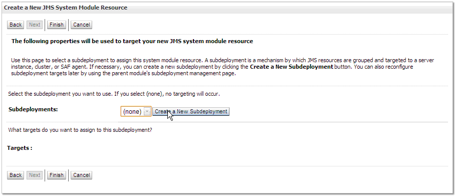
Description of "Figure 2-38 Create New JMS System Module Resource (New Subdeployment) screen"
-
If creating a new subdeployment, enter a name for the subdeployment (like JMSSubdeploy-TransServer) and then click OK.
Figure 2-39 Create a New Subdeployment screen
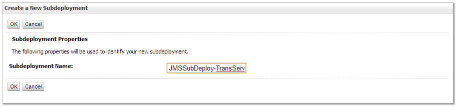
Description of "Figure 2-39 Create a New Subdeployment screen"
-
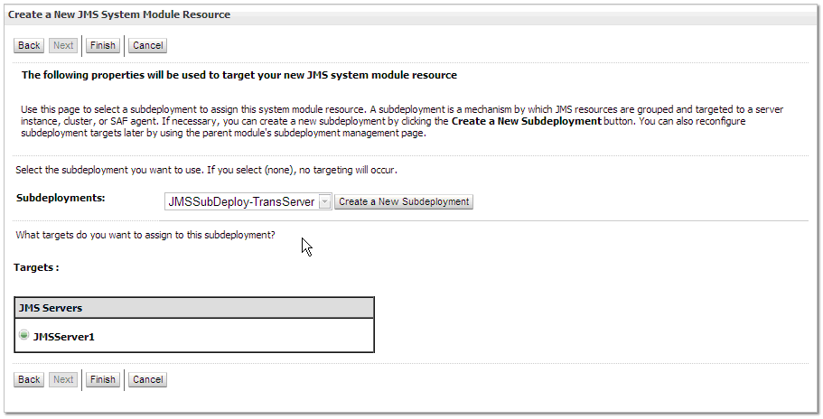
After you select the subdeployment, select the JMS Server as the target and then click Finish.
Figure 2-40 Create a New JMS System Module Resource (JMS Server) screen
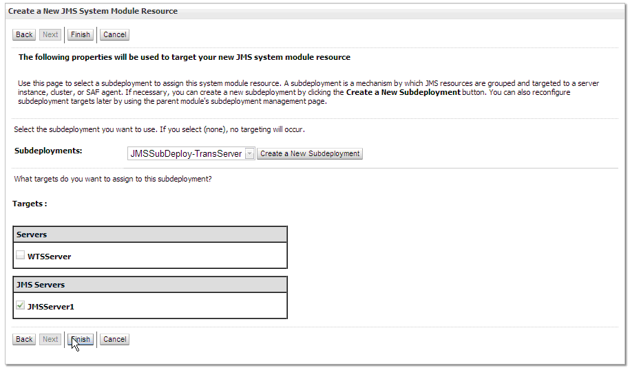
Description of "Figure 2-40 Create a New JMS System Module Resource (JMS Server) screen"
-
On the Settings for JMS Module screen, select the link for the newly created Connection Factory.
-
On the Settings for Connection Factory screen, select the General tab. Ensure that the Default Targeting Enabled checkbox is unchecked. Click Save.
Figure 2-42 Settings for Connection Factory screen
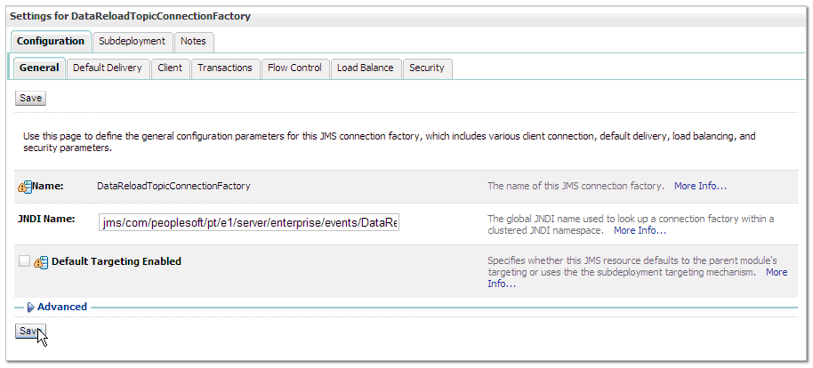
Description of "Figure 2-42 Settings for Connection Factory screen"
-
On the Setting for Connection Factory screen, select the Transactions tab. Ensure that the XA Connection Factory Enabled checkbox is checked. Click Save.
Figure 2-43 Settings for Connection Factory (Transactions) screen
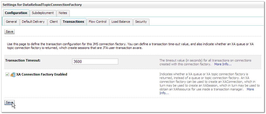
Description of "Figure 2-43 Settings for Connection Factory (Transactions) screen"
-
Once the connection factory is created, click Activate Changes in the Change Center screen.
2.5.2 JMS Queues
Use the steps below to create the following JMS Queue:
-
On the Settings for JMS Modules screen, click Lock and Edit and then click New.
Figure 2-45 Settings for JMS Modules screen
Description of "Figure 2-45 Settings for JMS Modules screen"
-
On the Create a New JMS System Module Resource screen, select the Queue radio button and then click Next.
Figure 2-46 Create a New JMS System Module Resource (Queue Radio) screen
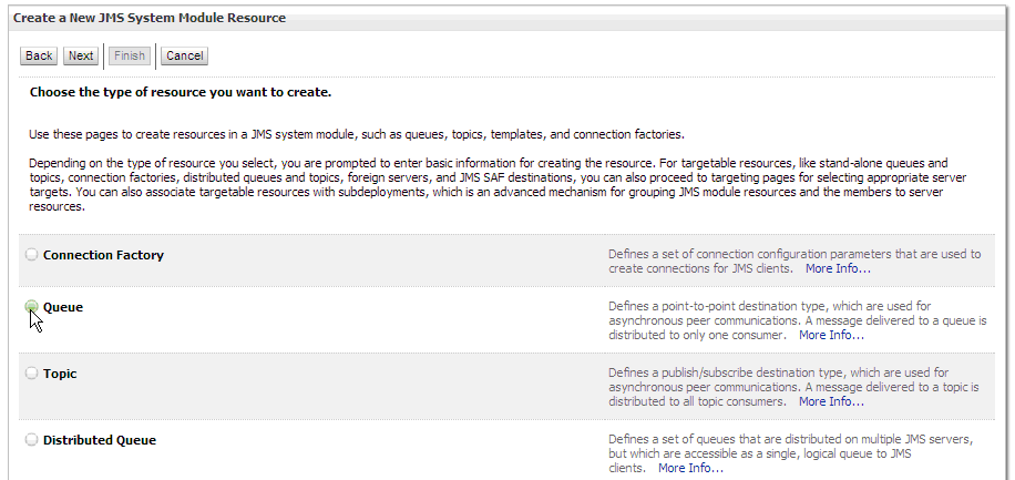
Description of "Figure 2-46 Create a New JMS System Module Resource (Queue Radio) screen"
-
On the JMS Destination Properties screen, enter the queue name and JNDI name exactly as it is above.
Figure 2-47 JMS Destination Properties screen
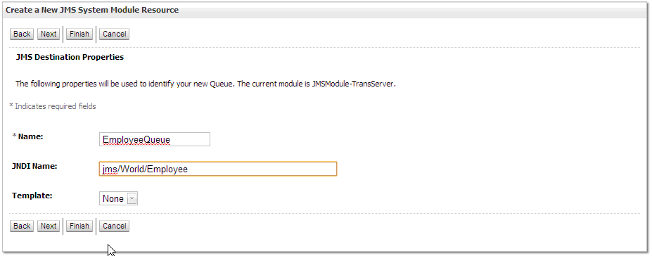
Description of "Figure 2-47 JMS Destination Properties screen"
-
On the JMS Queue Targeting screen, select the same subdeployment used for the connection factories from the drop down list. Make sure the JMS Server created earlier is selected as the Target. Click Finish.
-
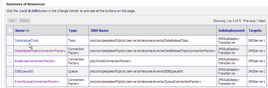
Once all the JMS Queue is created, click Activate Changes in the Change Center screen.
Figure 2-49 Change Center (JMS Queue) screen
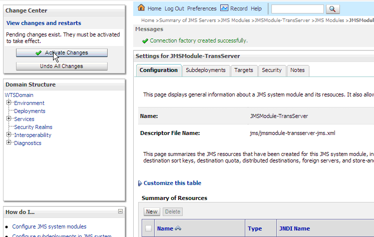
Description of "Figure 2-49 Change Center (JMS Queue) screen"