| Skip Navigation Links | |
| Exit Print View | |

|
Configuring and Administering Oracle Solaris 11.1 Networks Oracle Solaris 11.1 Information Library |
| Skip Navigation Links | |
| Exit Print View | |

|
Configuring and Administering Oracle Solaris 11.1 Networks Oracle Solaris 11.1 Information Library |
1. Planning the Network Deployment
2. Considerations When Using IPv6 Addresses
3. Configuring an IPv4 Network
4. Enabling IPv6 on the Network
5. Administering a TCP/IP Network
IP Tunnel Administration in Oracle Solaris 11
Tunnels in the Combined IPv6 and IPv4 Network Environments
Packet Flow Through the 6to4 Tunnel
Requirements for Creating Tunnels
Requirements for Tunnels and IP Interfaces
Tunnel Configuration and Administration With the dladm Command
Configuring Tunnels (Task Map)
How to Create and Configure an IP Tunnel
How to Configure a 6to4 Tunnel
How to Configure a 6to4 Tunnel to a 6to4 Relay Router
How to Modify an IP Tunnel Configuration
How to Display an IP Tunnel's Configuration
IP tunnels provide a means to transport data packets between domains when the protocol in those domains is not supported by intermediary networks. For example, with the introduction of the IPv6 protocol, IPv6 networks require a way to communicate outside their borders in an environment where most networks use the IPv4 protocol. Communication becomes possible by using tunnels. The IP tunnel provides a virtual link between two nodes that are reachable by using IP. The link can thus be used to transport IPv6 packets over the IPv4 networks to enable IPv6 communication between the two IPv6 sites.
In this Oracle Solaris release, tunnel administration has been revised to become consistent with the new model for network data-link administration. Tunnels are now created and configured by using new dladm subcommands. Tunnels can now also use other data-link features of the new administration model. For example, support for administratively-chosen names allows tunnels to be assigned meaningful names. For more information about the dladm subcommands, see the dladm(1M) man page.
Tunneling involves the encapsulation of an IP packet within another packet. This encapsulation allows the packet to reach its destination through intermediary networks that do not support the packet's protocol.
Tunnels differ depending on the type of packet encapsulation. The following types of tunnels are supported in Oracle Solaris:
IPv4 tunnels – IPv4 or IPv6 packets are encapsulated in an IPv4 header and sent to a preconfigured unicast IPv4 destination. To indicate more specifically the packets that flow over the tunnel, IPv4 tunnels are also called either IPv4 over IPv4 tunnels or IPv6 over IPv4 tunnels.
IPv6 tunnels – IPv4 or IPv6 packets are encapsulated in an IPv6 header and sent to a preconfigured unicast IPv6 destination. To indicate more specifically the packets that flow over the tunnel, IPv6 tunnels are also called either IPv4 over IPv6 tunnels or IPv6 over IPv6 tunnels.
6to4 tunnels – IPv6 packets are encapsulated in an IPv4 header and sent to an IPv4 destination that is automatically determined on a per-packet basis. The determination is based on an algorithm that is defined in the 6to4 protocol.
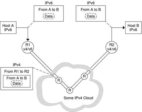
Most sites that have IPv6 domains communicate with other IPv6 domains by traversing IPv4 networks, which are more prevalent than IPv6–only networks. The following figure illustrates the tunneling mechanism between two IPv6 hosts through IPv4 routers, which are indicated in the figure by “R.”
Figure 6-1 IPv6 Tunneling Mechanism

In the figure, the tunnel consists of two routers that are configured to have a virtual point-to-point link between the two routers over the IPv4 network.
An IPv6 packet is encapsulated within an IPv4 packet. The boundary router of the IPv6 network sets up a point-to-point tunnel over various IPv4 networks to the boundary router of the destination IPv6 network. The packet is transported over the tunnel to the destination boundary router, where the packet is decapsulated. The router then forwards the separate IPv6 packet to the destination node.
Oracle Solaris includes 6to4 tunnels as a preferred interim method for making the transition from IPv4 to IPv6 addressing. 6to4 tunnels enable isolated IPv6 sites to communicate across an automatic tunnel over an IPv4 network that does not support IPv6. To use 6to4 tunnels, you must configure a boundary router on your IPv6 network as one endpoint of the 6to4 automatic tunnel. Thereafter, the 6to4 router can participate in a tunnel to another 6to4 site, or, if required, to a native IPv6, non-6to4 site.
This section provides reference materials on the following 6to4 topics:
Topology of a 6to4 tunnel
Description of the packet flow across a 6to4 tunnel
Topology of a tunnel between a 6to4 router and a 6to4 relay router
Points to consider before you configure 6to4 relay router support
The following table describes additional tasks to configure 6to4 tunnels and the resources to obtain additional useful information.
|
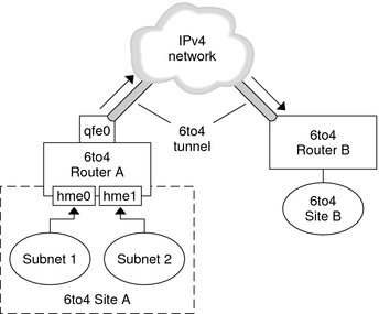
A 6to4 tunnel provides IPv6 connectivity to all 6to4 sites everywhere. Likewise, the tunnel also functions a link to all IPv6 sites, including the native IPv6 internet, provided that the tunnel is configured to forward to a relay router. The following figure shows how a 6to4 tunnel provides this connectivity between 6to4 sites.
Figure 6-2 Tunnel Between Two 6to4 Sites

The figure depicts two isolated 6to4 networks, Site A and Site B. Each site has configured a router with an external connection to an IPv4 network. A 6to4 tunnel across the IPv4 network provides a connection to link 6to4 sites.
Before an IPv6 site can become a 6to4 site, you must configure at least one router interface for 6to4 support. This interface must provide the external connection to the IPv4 network. The address that you configure on qfe0 must be globally unique. In this figure, boundary Router A's interface qfe0 connects Site A to the IPv4 network. Interface qfe0 must already be configured with an IPv4 address before you can configure qfe0 as a 6to4 pseudo-interface.
In the figure, 6to4 Site A is composed of two subnets, which are connected to interfaces hme0 and hme1 on Router A. All IPv6 hosts on either subnet of Site A automatically reconfigure with 6to4-derived addresses upon receipt of the advertisement from Router A.
Site B is another isolated 6to4 site. To correctly receive traffic from Site A, a boundary router on Site B must be configured for 6to4 support. Otherwise, packets that the router receives from Site A are not recognized and are then dropped.
This section describes the flow of packets from a host at one 6to4 site to a host at a remote 6to4 site. This scenario uses the topology that is shown in Figure 6-2. Moreover, the scenario assumes that the 6to4 routers and the 6to4 hosts are already configured.
A host on Subnet 1 of 6to4 Site A sends a transmission, with a host at 6to4 Site B as the destination. Each packet header has a 6to4-derived source address and 6to4-derived destination address.
Site A's router encapsulates each 6to4 packet within an IPv4 header. In this process, the router sets the IPv4 destination address of the encapsulating header to Site B's router address. For each IPv6 packet that flows through the tunnel interface, the packet's IPv6 destination address also contains the IPv4 destination address. Thus, the router is able to determine the IPv4 destination address that is set on the encapsulating header. Then, the router uses standard IPv4 routing procedures to forward the packet over the IPv4 network.
Any IPv4 routers that the packets encounter use the packets' IPv4 destination address for forwarding. This address is the globally unique IPv4 address of the interface on Router B, which also serves as the 6to4 pseudo-interface.
Packets from Site A arrive at Router B, which decapsulates the IPv6 packets from the IPv4 header.
Router B then uses the destination address in the IPv6 packet to forward the packets to the recipient host at Site B.
6to4 relay routers function as endpoints for tunnels from 6to4 routers that need to communicate with native IPv6, non-6to4 networks. Relay routers are essentially bridges between the 6to4 site and native IPv6 sites. Because this solution might be insecure, by default, Oracle Solaris does not enable 6to4 relay router support. However, if your site requires such a tunnel, you can use the 6to4relay command to enable the following tunneling scenario.
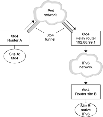
Figure 6-3 Tunnel From a 6to4 Site to a 6to4 Relay Router

In Figure 6-3, 6to4 Site A needs to communicate with a node at the native IPv6 Site B. The figure shows the path of traffic from Site A onto a 6to4 tunnel over an IPv4 network. The tunnel has 6to4 Router A and a 6to4 relay router as its endpoints. Beyond the 6to4 relay router is the IPv6 network, to which IPv6 Site B is connected.
This section describes the flow of packets from a 6to4 site to a native IPv6 site. This scenario uses the topology that is shown in Figure 6-3.
A host on 6to4 Site A sends a transmission that specifies as the destination a host at native IPv6 Site B. Each packet header has a 6to4-derived address as its source address. The destination address is a standard IPv6 address.
Site A's 6to4 router encapsulates each packet within an IPv4 header, which has the IPv4 address of the 6to4 relay router as its destination. The 6to4 router uses standard IPv4 routing procedures to forward the packet over the IPv4 network. Any IPv4 routers that the packets encounter forward the packets to the 6to4 relay router.
The physically closest anycast 6to4 relay router to Site A retrieves the packets that are destined for the 192.88.99.1 anycast group.
Note - 6to4 relay routers that are part of the 6to4 relay router anycast group have the IP address 192.88.99.1. This anycast address is the default address for 6to4 relay routers. If you need to use a specific 6to4 relay router, you can override the default and specify that router's IPv4 address.
The relay router decapsulates the IPv4 header from the 6to4 packets, revealing the native IPv6 destination address.
The relay router then sends the now IPv6-only packets onto the IPv6 network, where the packets are ultimately retrieved by a router at Site B. The router then forwards the packets to the destination IPv6 node.