2 Installation Planning
Physical Dimensions and Weights
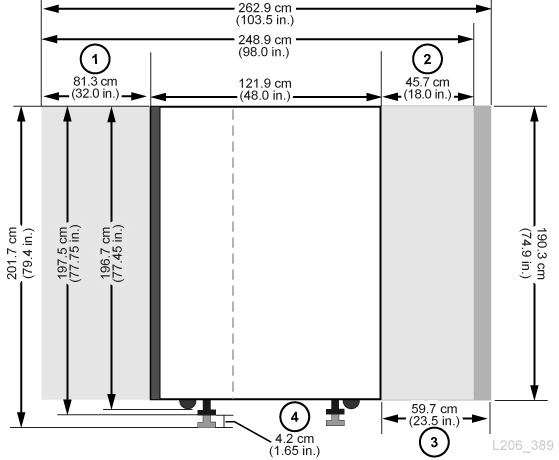
Figure Legend:
-
Base and DEM rear service clearance
-
Base and DEM front service clearance
-
AEM service clearance
-
Weight pad adjustment range
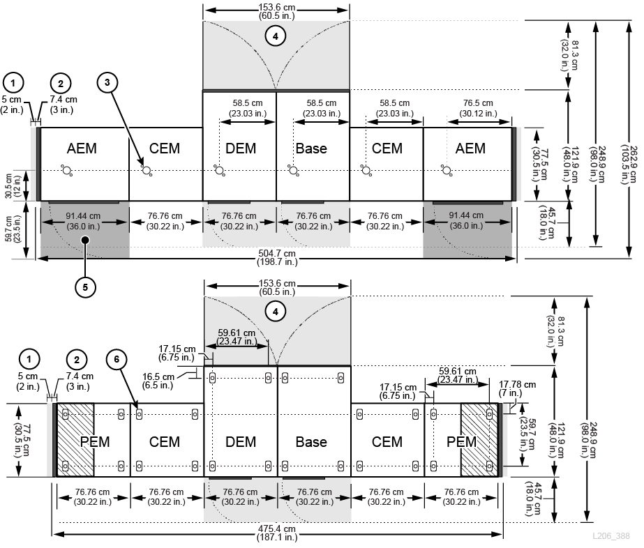
Figure Legend:
-
Side cooling area
-
Side cover
-
Nozzle cutout for fire suppression system
-
Base and DEM service clearance (light gray areas)
-
AEM service clearance (dark gray areas)
-
Weight distribution pad
Base Module
Table 2-1 Base Module Measurements
| Dimension Type | Measurement |
|---|---|
|
Height |
196.7 cm (77.45 in.) on casters for transport 197.5 cm (77.75 in.) to 201.68 cm (79.4 in.) on weight pads for permanent install |
|
Width |
76.8 cm (30.22 in.) when placed between modules 81.3 cm (32 in.) transport width (no side covers) Foot 1 91.5 cm (36 in.) standalone with side covers on both sidesFoot 2 |
|
Depth |
121.9 cm (48 in.) |
|
Service Area |
Front: 45.7 cm (18.0 in.) Rear: 81.3 cm (32.0 in.) Side Cooling Area: 5 cm (2 in.) Side Install Area: 45.7 cm (18.0 in.) |
|
Weight |
Frame only: 361 kg (796 lb) 8 drives and media: 623 kg (1372 lb) 16 drives and media: 661 kg (1457 lb) 24 drives and media: 687 kg (1514 lb) Side Covers: 18.5 kg (41 lb) per side |
Footnote 1 Minimum transportation clearance. There are alignment tabs on each side of the module that add 4.5 cm to the 76.8 cm width of the module. Therefore, 81.3 cm is the minimum transportation width.
Footnote 2 One side cover adds 7.4 cm (2.9 in.) to the module width. Only the ends of the library require side covers.
Drive Expansion Module
Table 2-2 Drive Expansion Module Measurements
| Dimension | Measurement |
|---|---|
|
Height |
196.7 cm (77.45 in.) on casters for transport: 197.5 cm (77.75 in.) to 201.68 cm (79.4 in.) on weight pads for permanent install |
|
Width (module only) |
76.8 cm (30.22 in.) when placed between modules 81.3 cm (32 in.) transport width (no side covers) Foot 1 83.8 cm (33 in.) with one side cover |
|
Depth (doors closed) |
121.9 cm (48 in.) |
|
Service Area |
Front: 45.7 cm (18.0 in.) Rear: 81.3 cm (32.0 in.) Side Cooling Area: 5 cm (2 in.) Side Install Area: 45.7 cm (18.0 in.) |
|
Weight |
Frame only, no CAP: 265 kg (584 lb) 8 drives and media: 540 kg (1190 lb), 582 kg (1284 lb) with CAP 16 drives and media: 596 kg (1314 lb), 621 kg (1369 lb) with CAP 24 drives and media: 647 kg (1426 lb), 660 kg (1456 lb) with CAP 32 drives and media: 709 kg (1564 lb), 723 kg (1594 lb) with CAP |
Footnote 1 Minimum transportation clearance. There are alignment tabs on each side of the module that add 4.5 cm to the 76.8 cm width of the module. Therefore, 81.3 cm is the minimum transportation width.
Cartridge and Parking Expansion Modules
Table 2-3 Cartridge and Parking Expansion Module Measurements
| Dimension | Measurements |
|---|---|
|
Height |
196.7 cm (77.45 in.) on casters for transport 197.5 cm (77.75 in.) to 201.68 cm (79.4 in.) on weight pads for permanent install |
|
Width (module only) |
76.8 cm (30.22 in.) when placed between modules/side cover 81.3 cm (32 in.) transport width (no side covers) Foot 1 83.8 cm (33 in.) with one side cover |
|
Depth |
77.5 cm (30.5 in.) |
|
Weight (CEM) |
Frame only: 175 kg (385 lb) Shipping: 213 kg (469 lb) Installed, with media: 340 kg (749 lb) |
|
Weight (PEM) |
Frame only: 175 kg (385 lb) Installed, with media: 257kg (567 lb) |
Footnote 1 Minimum transportation clearance. There are alignment tabs on each side of the module that add 4.5 cm to the 76.8 cm width of the module. Therefore, 81.3 cm is the minimum transportation width.
Access Expansion Module
Table 2-4 Access Expansion Module Measurements
| Dimension | Measurement |
|---|---|
|
Height |
196.7 cm (77.45 in.) on casters for transport 197.5 cm (77.75 in.) to 201.68 cm (79.4 in.) on weight pads for permanent install |
|
Width |
91.4 cm (36.0 in.) when placed between module and side cover 96 cm (37.8 in) transport width (no side covers) Foot 1 99.1 cm (39 in.) with one side cover |
|
Depth |
77.5 cm (30.5 in.) |
|
Service Area |
Front: 59.7 cm (23.5 in.) |
|
Weight |
Frame only: 204.2 kg (450 lb) |
Footnote 1 Minimum transportation clearance. There are alignment tabs on each side of the module that add 4.5 cm to the 91.5 cm width of the module. Therefore, 96 cm is the minimum transportation width.
Covers, Doors, and Service Clearances
Table 2-5 Covers, Doors, and Service Clearance Measurements
| Dimension | Measurement |
|---|---|
|
Height |
190.3 cm (74.9 in.) frame only |
|
Door thickness |
Front: 1.9 cm (0.75 in.) Rear: 4.5 cm (1.75 in.) |
|
Door latches |
2.53 cm (0.9 in.) |
|
Service clearance |
Front: 45.7 cm (18 in.) for Base and DEM only, 59.7 cm (23.5 in.) for AEM Rear: 81 cm (32 in.) for Base and DEM only Side: 5 cm (2 in.) for cooling, 45.7 cm (18.0 in.) for install |
|
Side cover |
7.4 cm (2.9 in.) width 18.5 kg (41 lb) each |
Shipping Weights and Measures
The SL3000 library modules and other components are shipped on pallets. The table below lists each module and its shipping specifications. If equipment on a pallet must be transported on elevators, the elevator cars must be capable of safely handling the weight.
Table 2-6 Module and Tape Drive Shipping Information
| Type | Height | Width | Depth | Weight |
|---|---|---|---|---|
|
Base |
216 cm (85 in.) |
97 cm (38.3 in.) |
134 cm (53 in.) |
410 kg (905 lb) |
|
DEM |
216 cm (85 in.) |
97 cm (38.3 in.) |
134 cm (53 in.) |
321 kg (708 lb) |
|
CEM |
216 cm (85 in.) |
97 cm (38.3 in.) |
96 cm (38 in.) |
213 kg (469 lb) |
|
PEM |
216 cm (85 in.) |
97 cm (38.3 in.) |
96 cm (38 in.) |
213 kg (469 lb) |
|
AEM |
216 cm (85 in.) |
97 cm (38.3 in.) |
148 cm (58 in.) |
260 kg (570 lb) |
|
LTO |
32 cm (12.6 in.) |
31 cm (12.2 in.) |
66 cm (26 in.) |
9.5 kg (20.9 lbs) |
|
T10000 |
34 cm (13.4 in.) |
31 cm (12.2 in.) |
66 cm (26 in.) |
10.5 kg (23.1 lbs) |
Either a split-pallet or pallet-ramp design is used to ship and provide safe removal of the module at the customer site. SL3000 library modules are shipped with wheels (casters) already attached to allow for easy positioning within the data center. Once positioned, the modules must be raised from their wheel-base to rest upon load plates for stability and leveling purposes.
The suggested library adjustment height is 200 cm (77.6 in.). Ensure the top of the library does not interfere with ceiling fixtures at the installation site.
Installation Site Requirements
Physical Space Requirements
The SL3000 library requires adequate physical space. For dimensions of the library modules, see "Physical Dimensions and Weights". If modules will be added in the future, ensure there is enough room to expand the library.
The minimum working area (not including the space required for the pallets) is approximately 19 m2 (200 ft2).
Transporting the Library
If the equipment must be transported on elevators, the elevator cars must be capable of safely handling the weight. Additionally, ensure that the components can pass through doorways and fit in elevators. For more information, see "Shipping Weights and Measures".
Pallet Double Stacking
WARNING:
Possible Physical Injury. Only use a forklift operated by a qualified operator to remove a stacked second pallet. Do not attempt to tilt or slide the pallet off by hand.
In the event that a forklift is unavailable to safely remove the module, notify the installation coordinator. Inform them that the library may need to be picked up from the site by the delivery company, taken off the second pallet, and re-delivered. Delivery personnel are not authorized to remove the modules from the second pallet without proper equipment.
Floor Requirements
You can install the SL3000 library on a raised, solid, or carpeted floor with a smooth surface, as long as there is adequate airflow. If the floor is raised, ensure there are no ventilation panels directly below the library. If the floor is solid, you should route cables from the ceiling to avoid creating a tripping hazard. If the floor is carpeted, ensure the carpet is approved for computer-room equipment and provides protection from electrostatic discharge (ESD).
Weight
Verify the site floor can support the weight of the library. It must support 454 kg (1,000 lb) per weight distribution pad. There are four distribution pads per module, and each measures 4 by 8 inches.
If the equipment must be transported on elevators, the elevator cars must be capable of safely handling the weight. Depending on the library configuration, the weight of the library can vary (see "Physical Dimensions and Weights").
Environmental Requirements
For optimal reliability, maintain the environment between the recommended ranges. Although this equipment is designed to operate in environmental conditions of 20% to 80% humidity, a recommended industry best practice is to maintain a relative humidity of 40% to 50%.
Table 2-7 Environmental Specifications
| Description | Temperature | Relative Humidity (non-condensing) | Wet Bulb Maximum | Maximum Altitude |
|---|---|---|---|---|
|
Operating |
15 to 32°C (60 to 90°F) dry bulb |
20% to 80% |
29.2°C (84.5°F) |
3.05 km (10,000 ft) |
|
Storage |
10 to 40°C (50 to 104°F) |
10% to 95% |
35.0°C (95.0°F) |
3.05 km (10,000 ft) |
|
Shipping |
-40 to 60°C (-40 to 140°F) |
10% to 95% |
35.0°C (95.0°F) |
15.24 km (50,000 ft) |
Airborne Contaminants
Airborne particulates can damage tape libraries, drives, and tapes. The operating environment for the tape library must meet to the following requirements:
-
ISO 14644-1 Class 8 Environment
-
Total mass of airborne particulates must be less than or equal to 200 micrograms per cubic meter
-
Severity level G1 per ANSI/ISA 71.04-1985
Particles ten microns or smaller are particularly harmful to most data processing hardware. Gasses that are particularly dangerous to electronic components include chlorine compounds, ammonia and its derivatives, oxides of sulfur, and petrol hydrocarbons. In the absence of appropriate hardware exposure limits, health exposure limits must be used.
Humidification with chlorinated water is a common source of airborne chlorine. Appropriately-designed carbon filters must be used to ensure safe levels of airborne chlorine when chlorinated water is used for humidification.
Table 2-8 Gas Limit Recommendations
| Chemical | ASHRAE | OSHA (PEL) | ACGIH | NIOSH |
|---|---|---|---|---|
|
Acetic Acid (CH3COOH) |
Not defined |
10 ppm |
Not defined |
Not defined |
|
Ammonia (NH) |
3500 µg/m3 |
350 ppm |
25 ppm |
Not defined |
|
Chlorine (Cl) |
2100 µg/m3 |
31 ppm (c) |
Not defined |
0.5 ppm (c) |
|
Hydrogen Chloride (HCl) |
Not defined |
5 ppm (c) |
Not defined |
Not defined |
|
Hydrogen Sulfide (H2S) |
50 µg/m3 |
320 ppm (c) |
10 ppm |
10 ppm |
|
Ozone (O3) |
235 µg/m3 |
30.1 ppm |
Not defined |
Not defined |
|
Petrol-hydrocarbons (CnHn) |
Not defined |
500 ppm |
75 ppm |
300 ppm |
|
Sulfur Dioxide (SO2) |
80 µg/m3 |
35 ppm |
2 ppm |
0.5 ppm (c) |
|
Sulfuric Acid (H2SO4) |
Not defined |
1 ppm |
Not defined |
1 ppm (c) |
Some basic precautions to follow:
-
Do not allow food or drink into the data center.
-
Do not store cardboard, wood, or packing materials in the data center clean area.
-
Identify a separate area for unpacking new equipment from crates and boxes.
-
Do not allow construction or drilling in the data center without first isolating sensitive equipment. Dry wall and gypsum are especially damaging to equipment.
Seismic or Earthquake Ratings
The requirements for seismic compatibility vary dramatically throughout the world. Therefore, Oracle does not offer a standard "seismic" feature for the SL3000 library. If you have seismic concerns, Oracle recommends that you work with local experts who are familiar with the local code and requirements. Professional Services can also help coordinate this activity.
Caution:
Bodily injury and equipment damage: You must consult a qualified seismic engineer to verify seismic zone exposures and adequate site preparation.For sites in areas of seismic activity, you might want to permanently fix the library position for added stability. The SL3000 library provides mounting holes in the floor of each module where half-inch carriage bolts (mounting studs) can be used to permanently fix the library's position.
Power Requirements
For power requirements, heat output, and power consumption, see "Power Configurations".
Waste Disposal
Plan for the disposal of all packing material. Determine if waste bins or recycling containers will be provided on site or whether an independent company will handle the disposal at additional cost.
Fire Suppression Planning
The library does not ship with a fire suppression system, but each module has a 5 cm (2 inch) diameter nozzle opening (see Figure 2-2). Plates, 7 cm (2.75 inch) square and 1.2 mm (0.048 inch) thick, cover the openings and can be drilled to custom fit nozzles. Nozzles must be clear of robotic operations and cannot protrude more than 1.9 cm (0.75 inches) into the library. Professional Services can assist with fire suppression planning (contact your Oracle sales representative).
Networking
If possible, use a dedicated and secure private network for communication between the library and host management software. A secure private network connection using an Ethernet hub or switch is required for maximum throughput and minimum resource contention.
If a shared network must be used:
-
Place the library on its own subnet.
-
Directly connect the library to a switch and use a managed switch that can:
-
-
Set priorities on ports to give the host and library higher priority.
-
Provide dedicated bandwidth and create a VLAN between the host and the library.
-
-
Use a virtual private network (VPN) to insulate host and library traffic.
Cable Routing
The SL3000 library has rear door cut-outs on both the top and bottom of the door to allow for cable routing. The cut-out is a 2.5 cm (1 inch) opening that runs 73 cm (29 inches) along the length of the door with cable routing hardware and reliefs available.
Note:
The Base module and DEM have square holes on the face of rear door. These are for access to the PDUs, not for cable routing.When routing cables, make sure to include locations for power, drive interface, library control, and Ethernet cables. As a best practice, route power cables through one cut-out and signal cables through another cut-out.
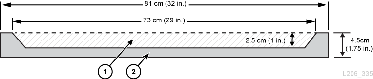
Figure Legend:
-
Cable routing area
-
Top/bottom view of rear door
AC Power Cables
SL3000 libraries require that you select one of the following single phase AC power options for the Base module and DEM:
-
110 VAC, 50/60 Hz, at 20 Amps (range: 100–127 VAC, 50–60 Hz, 16 Amps)
-
240 VAC, 50/60 Hz, at 30 Amps (range: 200–240 VAC, 50–60 Hz, 24 Amps)
Make sure to plan for the locations of power cables and list the locations for their associated circuit breakers. Cables must be ordered for the appropriate power configuration. Order one power cord per PDU installed:
-
N+1 — one power cord for the Base module and an additional power cord for the DEM (if installed).
-
2N or 2N+1 — two power cords for the Base module and two additional power cords for the DEM (if installed).
Library Network and Tape Drive Cables
The library can be used in a 62.5-micron-cable Storage Area Network (SAN). However, the cable that connects the library to the network must be a 50-micron cable. The maximum distances supported on a Fibre Channel link are determined by the link speed, the type of fiber (50 or 62.5 micron), and the device to which the library is attached. Refer to your switch vendor to determine what is supported in your storage area network.
The typical support distances for the cables are:
-
4 Gbps = up to 70 m (230 ft) for 62.5-micron, 150 m (492 ft) for 50-micron
-
2 Gbps = up to 150 m (492 ft) for 62.5-micron, 300 m (984 ft) for 50-micron
-
1 Gbps = up to 175 m (574 ft) for 62.5-micron, 500 m (1640 ft) for 50-micron
If your library attaches to a host bus adapter (HBA), refer to the documentation for the HBA for the supported cable distances. For a list of cables, see "Cables".
If your library will support encryption, refer to the Oracle Key Manager Overview and Planning Guide on OTN.
Approximate Installation Time
The table below shows the estimated times for the installation of modules and components. At least two qualified service representatives should install the library. The times listed below do not include library initialization, testing, audits, and feature upgrades. Installation services are required with the purchase of the SL3000 library. Contact an Oracle sales representative for more information.
Table 2-9 Installation Time Estimates
| Module/Component | Time Estimate (hours) | Personnel Required | Total Person Hours |
|---|---|---|---|
|
Base with 8 drives (standard) |
3 |
2 |
6 |
|
Base and DEM |
5 |
2 |
10 |
|
Base and CEM |
4 |
2 |
8 |
|
Each additional CEM |
2 |
2 |
4 |
|
Two PEMs |
2 |
2 |
4 |
|
AEMs (each) |
2 |
2 |
4 |
|
CAPs |
1 |
2 |
2 |
|
Tape drive (each drive) |
0.5 |
1 |
0.5 |
|
Operator panel or window |
0.75 |
1 |
0.75 |
|
Firmware |
0.2 |
1 |
0.2 |
|
Integration (cables, hubs, switches, connections) |
8 |
1 |
8 |
|
Media install (each) |
0.02 |
1 |
variable |
Installation Tools
The tables below list the installation tools required for the SL3000 library. Oracle service personnel should obtain the standard tools locally or from the SL8500 installation kit if available.
Table 2-10 Standard Installation Tools
| Standard Tools | Use |
|---|---|
|
Torx screwdriver with T8, T10, T15, T25 bits |
T8: Removal and replacement of the PUK card. T10: PUO, PUW, PUN, PUF, PUZ cards. Track stops. T15: Operator panel, window, blank plate, arrays T25: Shipping brace, rails, and CAP screws. |
|
3/8-in. drive ratchet wrenchFoot 1 |
Module height adjustment, joining modules |
|
5/16-in. hex Allen on 3/8-in. driveFootref 1 |
Module height adjustment, joining modules |
|
9/16-in. socket on 3/8-in.-driveFootref 1 |
Module removal from pallet |
|
Adjustable wrench (must accept 7/8-in. nut) |
Lock weight distribution pads |
|
Phillips and flat blade screwdrivers |
General assembly |
|
Power drill (optional) |
General assembly. Adjust the torque settings to 2.8 Nm (25 in.-lb) for T-25 screws and 0.6 Nm (5 in.-lb) for T-10 screws. |
|
Wire side cutters |
Cutting shipping straps |
|
Multimeter |
Electrical testing |
|
Flashlight, step stool |
General assembly |
|
Pallet jack |
Moving equipment |
Footnote 1 Can be obtained from the SL8500 tool kit.
Table 2-11 Special Installation Tools
| Special Tools | Part Number | Use |
|---|---|---|
|
313921001 |
Track terminator removal (obtain from Base installation kit) |
|
|
Rail separator/joiner |
4199410xx |
Release or join extrusions (obtain from Base installation kit) |
|
Serial cable for laptop |
24100134 |
CLI access to library (obtain from iProcurement/Zones) |
|
Crossover cable for laptop |
24100163 |
Ethernet access to library (obtain from iProcurement/Zones) |
|
Drive tray power-on tool |
314831204 |
See "Drive Tray Power-on Tool" below (obtain from iProcurement/Zones) |
Drive Tray Power-on Tool
A tool is available to assist in removing a stuck tape within a library tape drive. This tool turns on a drive outside the library. The drive tray toolkit (part number 314831204) contains instructions and a drive power cable (part 419632401).
Note:
An AC power cord is required to use this tool. You must obtain a cord that is appropriate for your region.The tool is available from iProcurement under the Zones online tool crib.