1 Library Overview
Library Modules
-
Base Module — one required per library.
-
Drive Expansion Module (DEM) — maximum of one on the left side of a Base module only.
-
Cartridge Expansion Module (CEM) — maximum of eight with four on the left side of the library and four on the right side.
-
Access Expansion Module (AEM) — maximum of two with one on each end of the library. An AEM cannot be installed directly to the left of the Base module.
-
Parking Expansion Module (PEM) — an alternative to an AEM for redundant electronics support. PEMs must be installed as a pair, with one on each end of the library. A PEM is a converted CEM.
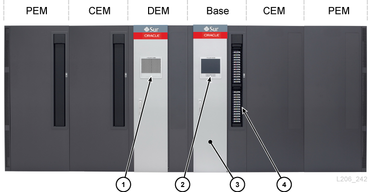
Figure Legend:
-
Perforated window
-
Operator panel
-
Service door
-
CAP (open)
Base Module
One Base module is required in every library. A standalone Base module is the smallest possible configuration of an SL3000 library.
Base Module Configuration Options
-
205 to 431 cartridge capacity (see "Calculating Physical Capacity").
-
8 (standard), 16, or 24 drive slots.
-
Perforated window (standard), window storage array, or operator panel.
-
CAP (standard). See "Rotational Cartridge Access Port (CAP)".
The front of the Base module contains a single CAP, service door, front panel with LEDs, and a perforated window, optional operator panel, or window storage array. The rear of the Base module contains the electronics module, power distribution units (PDUs), DC power supplies, tape drives, and two 1-unit rack spaces.
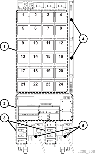
Figure Legend:
-
Tape drives
-
Electronics module
-
Drive DC power supplies
-
Ethernet switches (optional)
-
Power distribution units
Drive Expansion Module (DEM)
The DEM is attached to the left side of the Base module (when viewed from the front of the library). The DEM expands the number of tape drives and provides additional cartridge storage. There can be only one DEM per library.
-
153 to 522 cartridge capacity (see "Calculating Physical Capacity").
-
8 (standard), 16, 24, or 32 drive slots.
-
Perforated window (standard), window storage array, or operator panel.
-
CAP (optional), See "Rotational Cartridge Access Port (CAP)".
The front of the DEM contains a service door, optional CAP, and a perforated window or optional operator panel (if not already in the Base module) or window storage array. The rear of the DEM contains tape drives, PDUs, DC power supplies, and two 1-unit rack spaces.
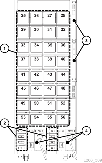
Figure Legend:
-
Tape drives
-
Drive DC power supplies
-
Ethernet switches (optional)
-
Power distribution unit
Cartridge Expansion Module (CEM)
The CEM provides additional cartridge storage. There are no tape drives present within this module. CEMs on the end of the library can be converted to PEMs (see "Parking Expansion Module (PEM)"). A maximum of eight CEMs are supported in a single library. The initial CEM should be installed to the right of a Base module, then a second to the left of the DEM/Base module, a third to the right, and the fourth one to the left, and so on. This alternating method maximizes library performance.
-
438 to 620 cartridge capacity (see "Calculating Physical Capacity").
-
CAP (optional). See "Rotational Cartridge Access Port (CAP)".
-
Placement to the left or right of a Base module and DEM
-
A maximum of four CEMs on each side of centerline (eight total)
Access Expansion Module (AEM)
An AEM has a large cartridge access door used for bulk loading and unloading of up to 234 cartridges. Additionally, a library with two AEMs supports the redundant robotics feature (see "Robotics"). A sliding safety door sections off a defective robot, allowing a service representative to access the disabled robot while the library remains online.
Note:
AEMs and PEMs cannot be installed in the same library.-
Must be placed on the ends of the library. An AEM cannot be installed directly to the left of the Base module; there must be a module in between.
-
A single AEM supports bulk load capabilities only. You should install a single AEM on the left for an additional 104 storage slots (see "Calculating Physical Capacity").
Parking Expansion Module (PEM)
The PEM is a converted CEM used to "park" a defective robot without blocking access for the operational robot in a redundant robotics configuration (see "Robotics"). Performing maintenance on a disabled robot in a PEM is disruptive to library operations.
The parking space causes six columns of cartridge arrays in the PEM to become inaccessible (three on the front wall and three on the rear wall). You do not need to remove the inaccessible arrays. The module can be restored to a CEM at anytime.
-
230 to 312 cartridge capacity (see "Calculating Physical Capacity").
-
Only the left PEM can have an optional CAP.
-
Must be installed on each end of the library.
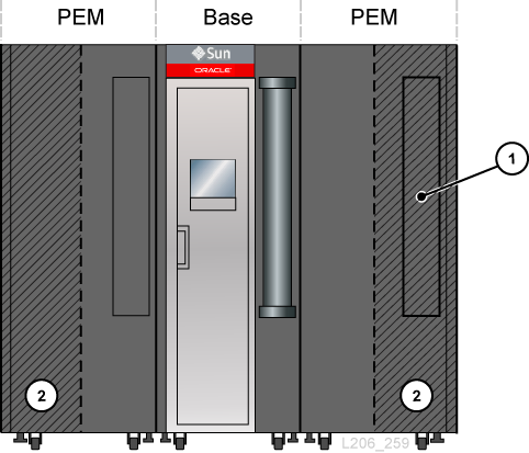
Figure Legend:
-
Inaccessible CAP area
-
Robot parking area (inaccessible cartridge slots)
Hardware Components
Electronics Control Module
The electronics control module (ECM) is responsible for electronics control, robot and drive control, and host connectivity. The ECM is located in the rear of the Base module (see Figure 1-2). The main controller cards are the HBCR (library controller) and HBT (drive controller).
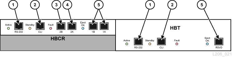
Figure Legend:
-
Serial port (reserved)
-
Serial port (CSE port for CLI)
-
Primary Ethernet port
-
Dual TCP/IP Ethernet port
-
Ethernet port (reserved)
Note:
The ECM ships with an optional MPU2 card (2Gb) or PUA2 card (8 Gb) for Fibre Channel interface connections. This card is not shown in the figure but is installed below the HBCR card.Command Line Interface
The command line interface (CLI) can be used by Oracle support to configure and diagnose the library. Service representatives can access the CLI through the electronic control module using either of the following:
-
Serial Port Connection on the HBCR card (RS-232) and a HyperTerminal connection to enter the commands
-
Ethernet Port Connection (ports 1A, 2A, or 2B) on the HBCR card and a secure shell (PuTTY) to enter the commands
Redundant Electronics
The optional redundant electronics (RE) feature is available for failover protection for the HBCR controller card. With the RE feature, each library has two HBCR controller cards. If the active library controller experiences errors, operations switch automatically to the stand-by library controller, with minimal disruption to library and host operations.
RE is not available for libraries that use the direct FC-SCSI connection to hosts.
For more information, see "Redundant Electronics Overview".
Robotics
Each library can have either one (standard) or two robots (known as redundant robotics). Robots retrieve and insert cartridges into CAPs or slots and mount or dismount cartridges from tape drives.
Robots move along two rails on the rear wall of the library. One rail is at the top of the library and one rail attaches to the floor. Two copper strips in the top rail provide power and a signal path between the robot and library controller (HBCR) card. Power is supplied from +48 VDC 1200 W load-sharing supplies (see "Power Configurations").
Robots contain a barcode scanner that reads the configuration blocks in each module during library initialization and identifies volume serial numbers (VOLSERs) of cartridges during CAP entries and audits.
Rotational Cartridge Access Port (CAP)
A CAP is a vertically-mounted, rotating cylinder with two removable 13-slot magazines.
-
The Base module comes standard with a CAP.
-
The DEM and CEMs can have one optional CAP per module. Only the left PEM can contain a CAP.
-
There can be a maximum of 10 rotational CAPs per library.
-
Each CAP has a keypad with an unlock indicator and a button to open the CAP.
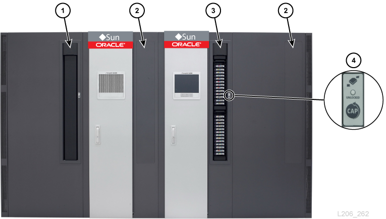
Figure Legend:
-
CAP (closed)
-
No CAP installed
-
CAP (open)
-
Keypad
Bulk Load Cartridge Access Ports (AEM)
An AEM allow you to enter and eject up to 234 cartridges without disrupting library operations. Only one AEM is required in a library to support the bulk loading feature (see "Access Expansion Module (AEM)").
Supported Tape Drives
-
StorageTek T-Series (T9840C and D)
-
StorageTek T-Series (T10000A, B, C, and D)
-
HP LTO generations 3, 4, 5, and 6
-
IBM LTO generations 3, 4, 5, 6, 7, and 8
Note:
LTO-8 drives can read and write one generation back. LTO-5, 6, and 7 drives can read two generations back and write one generation back. For best capacity and performance, always use cartridges of the same generation as your drives.Note:
Tape drives must support the dynamic World Wide Name feature to be placed online by the SL3000 library.Most drives are capable of reading the data recorded by an earlier generation tape drive from the same family. Therefore, you can use existing cartridges if they are within their warranty period.
For more information, refer to the tape drive section on the Oracle website: http://www.oracle.com/us/products/servers-storage/storage/tape-storage/overview/index.html
Encryption Capable Tape Drives
-
StorageTek T10000 A, B, C, D
-
StorageTek T9840 D
-
HP LTO generations 4, 5, 6
-
IBM LTO generations 4, 5, 6, 7
For more information, see "Tape Drive Encryption".
Power Configurations
The power configuration depends on the power source and redundancy.
AC Power Source Options
Each PDU installed in the library requires a separate AC power source. There can be a maximum of four PDUs in the library depending on the configuration selected (two in the Base module and two in the DEM). There are two AC power source options. Both are single phase:
-
120 VAC, 50/60 Hz, at 20 amps (range: 100–127 VAC, 47–63 Hz, 16 amps)
-
Limited support for T9840 and T10000 drives; no redundant robotics support
-
-
240 VAC, 50/60 Hz, at 30 amps (range: 200–240 VAC, 47–63 Hz, 24 amps)
-
Supports all drive types and redundant robotics
-
Power Redundancy Options
There are three power configurations that offer various levels of power redundancy.
N+1 power configuration (standard)
-
Offers DC power redundancy only
-
Consists of one PDU (per Base module or DEM), with one extra drive DC supply and one extra robotics DC supply
-
Provides N+1 DC power supply redundancy
-
Limited support for T9840 and T10000 drives and no redundant robotics support
2N power configuration
-
Offers both AC and DC power redundancy
-
Consists of two PDUs (per Base module or DEM) for AC redundancy, with a set of DC power supplies for each PDU
-
Provides N DC power supplies per PDU
-
Requires two separate AC input sources per Base module or DEM
-
Required for redundant robotics and redundant electronics support
2N+1 power configuration
-
Offers both AC and DC power redundancy with additional DC redundancy
-
Consists of two PDUs (per Base module or DEM) for AC redundancy, with additional DC power supplies for each PDU
-
Provides N+1 DC power redundancy for each PDU (except the second PDU only has N DC power supply redundancy for the robot)
-
Requires two separate AC input sources per Base module or DEM
-
Supports redundant robotics and redundant electronics
DC Power Supplies
There are two types of DC power supplies:
-
Load sharing 1200W DC — used for the robotics unit and tape drives
-
200W cPCI — used for the electronics control module
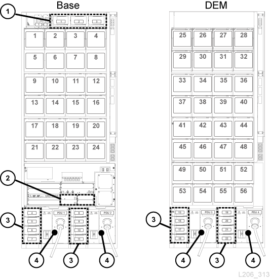
Figure Legend:
-
Robotics DC power supplies (1200W DC)
-
Electronics module DC power supplies (200W cPCI)
-
Tape drive DC power supplies (1200W DC)
-
Power distribution unit (120 VAC or 240 VAC)
Electronics Control Module Power Supplies
The electronics control module (ECM) uses 200 W cPCI power supplies. These power supplies are located below the HBT card in the Base module (there are no ECM power supplies in the DEM) — see Figure 1-7. The power supply for the electronics control module is different from the power supplies used for the robotics unit and the tape drives.
Each Base module ships standard with two ECM power supplies used for N+1 and 2N configurations. Order two additional ECM supplies for the 2N+1 configuration (see "DC Power Supplies").
Robotics Unit Power Supplies
The robotics unit uses load-sharing 1200 W DC power supplies located at the top of the Base module (the DEM does not contain robotics DC supplies) — see Figure 1-7. The 1200 W DC power supply used for the robotics unit is the same power supply used for the tape drives.
Each Base module ships standard with two robotics DC power supplies used for N+1 and 2N configurations. Order a third DC power supply for the 2N+1 configuration (see "DC Power Supplies").
Tape Drive Power Supplies
The tape drives use load-sharing 1200 W DC power supplies. Up to four tape drive power supplies are located to the left of each PDU in both the Base module and the DEM — see Figure 1-7.
The library ships with two tape drive DC power supplies per Base module and two tape drive DC power supplies per DEM. The number of tape drive DC power supplies required depends on the power configuration selected and the number and type of tape drives in the library. To calculate the number of power supplies to order, see "Calculating Tape Drive Power Supply Quantities" below.
Calculating Tape Drive Power Supply Quantities
The number of power supplies required depends on:
-
Power configuration (120 VAC or 240 VAC with N+1, 2N, or 2N+1)
-
Number and type of tape drive (T10000, T9840, or LTO)
To determine the number of power supplies required for a library configuration:
-
Determine the total number of each drive type.
-
Multiply by the watts-per-drive for each drive type, see Table 1-1, "Watts Per Drive".
-
Add together the watts used by each drive type to calculate the total watts consumed.
-
Use Table 1-2 through Table 1-5 to determine the number of DC power supplies needed.
For ordering part numbers, see "DC Power Supplies".
Power Supplies Required for 120 VAC PDUs
To use 120 VAC PDUs, the total watts used by the drives must be less than 843 W in the Base module and less than 1,481 W in the DEM. If the total watts exceeds 843 W in the Base module or 1,481 W in the DEM, 240 VAC PDUs are required. You cannot mix 120 VAC with 240 VAC PDUs within the library. All PDUs must be the same type.
Power Supplies Required for 240 VAC PDUs
If the total watts used by the drives exceeds 843 W in the Base module or 1,481 W in the DEM, 240 VAC PDUs are required. You cannot mix 120 VAC with 240 VAC PDUs within the library. All PDUs must be the same type.
Example: Calculating Required Number of Drive DC Power Supplies
The example library has a Base module and a DEM with all three drive types (T10000, T9840, LTO). Table 1-6 and Table 1-7 show how to calculate the total watts used by the tape drives in the Base module and DEM:
Table 1-6 Base Module Tape Drive Watts Consumption Example
| Drive Type | Quantity of Drives | Multiply by Watts Per Drive | Total Watts Per Drive Type |
|---|---|---|---|
|
T10000D |
6 |
127 |
762 |
|
T9840D |
6 |
100 |
600 |
|
LTO7 |
4 |
46 |
184 |
The drives in the Base module use 1,546 W. In Table 1-2, 1,546 W exceeds the maximum 843 W supported by a 120 VAC PDU. Therefore, the Base module requires a 240 VAC PDU to support the drive configuration — refer to Table 1-4.
Table 1-7 DEM Tape Drive Watts Consumption Example
| Drive Type | Quantity of Drives | Multiply by Watts Per Drive | Total Watts Per Drive Type |
|---|---|---|---|
|
T10000C |
4 |
93 |
372 |
|
T9840D |
2 |
100 |
200 |
|
LTO5 |
4 |
46 |
184 |
The drives in the DEM use 756 W. In Table 1-3 and Table 1-5, either a 120 VAC or 240 VAC PDU can support 756 W. However, you cannot mix 120 VAC with 240 VAC PDUs within the library. Therefore, the example library requires 240 VAC PDUs.
Two tape drive DC power supplies ship standard with the Base module and two power supplies ship standard with the DEM. Therefore, subtract two from the DC supplies required. Use Table 1-4 and Table 1-5 to determine what to order.
The tables below list the power supplies required for the example library.
Table 1-8 DC Supplies Required for Base Example
| Configuration Option | DC Supplies Required | DC Supplies to Order (= Required - 2) |
|---|---|---|
|
N+1 (240 VAC PDU) |
3 |
1 |
|
2N (240 VAC PDU) |
4 |
2 |
|
2N+1 (240 VAC PDU) |
6 |
4 |
Table 1-9 DC Supplies Required for Drive Expansion Module - Example
| Configuration Option | DC Supplies Required | DC Supplies to Order (= Required - 2) |
|---|---|---|
|
N+1 (240VAC PDU) |
2 |
0 |
|
2N (240VAC PDU) |
2 |
0 |
|
2N+1 (240VAC PDU) |
4 |
2 |
The number of drive DC supplies that must be ordered depends on the power configuration selected. For instance, if the example library had a 2N+1 configuration, it would require an order of six additional drive DC power supplies (four supplies for the Base module and two supplies for the DEM). The 2N+1 also requires an additional DC supply for the robotics and an additional ECM 200W cPCI power supply. The ECM power supply is different than the tape drive and robot power supplies listed in this example. For ordering information, see "DC Power Supplies."
AC Power Cables
The following table lists the cables required for each power configuration. You must order one power cord per PDU installed:
-
N+1 — order one power cord for the Base module and an additional power cord for the DEM (if installed)
-
2N or 2N+1 — two power cords for the Base module and two additional power cords for the DEM (if installed)
Table 1-10 Power Cable Descriptions
| Power Source | Description | Circuit Breaker | Wall Connector | Library Connector | Power CordLength/Type |
|---|---|---|---|---|---|
|
120 VAC/20A |
US/Japan |
20A |
L5-20P |
L5-20R |
3.7 m (12 ft) 12 AWG |
|
240 VAC/30A |
US |
30A |
L6-30P |
L6-30R |
3.7 m (12 ft) 12 AWG |
|
240 VAC/30A |
International |
30A |
330P6W |
L6-30R |
4 m (13 ft) HAR |
Power Consumption
For environmental or economical reasons, you might want to determine the total power consumption (watts), CO2 emission values, and British Thermal Units (Btu/hr) for the SL3000 library and tape drives. The table below provides power consumption in watts.
Table 1-11 Power Consumption Values
| Components | Quantity | Idle Watts | Max Watts |
|---|---|---|---|
|
Base Library (required) Includes: 1 ECM, 1 robot, and 1 CAP |
1 |
156 |
197 |
|
Redundant Electronics (optional) |
1 |
100 |
100 |
|
Redundant Robotics (optional) |
1 |
28 |
55 |
|
Operator Panel (optional) |
1 |
29 |
37 |
|
Additional CAPs (optional) |
Each |
10 |
14 |
|
Access Expansion Module (optional) |
Each |
8 |
30 |
|
T9840 |
Each |
79 |
100 |
|
T10000A/B/C |
Each |
61 |
93 |
|
T10000D |
Each |
64 |
127 |
|
LTO |
Each |
30 |
46 |
Calculating Total Watts, CO2 Emissions, and Btu/hr
To calculate the total power consumption in Watts for the library, add up all the applicable wattage values for the library configuration from Table 1-11.
To calculate kilograms of CO2 emissions per day, multiply watts by the CO2 emissions constant. Use the constant that is applicable for your country (0.02497 for US).
To convert electrical values to Btu/hr, multiply the number of watts by 3.412 (1 W =3.412 Btu/hr). Many manufacturers publish kW, kVA, and Btus for their equipment. Use the information provided by the manufacturer. Otherwise, use the formula below.
-
3.41214 x Watts =Btu/hr
Power Consumption Example 1
Using the maximum continuous values for the following components:
Table 1-12 Power Consumption Example
| Quantity | Component Description | Watts |
|---|---|---|
|
1 |
SL3000 Base (including one ECM, one robot, one CAP) |
197 |
|
16 |
LTO7 Tape Drives |
736 |
|
-- |
Total |
933 |
-
Emissions: 933W x 0.02497 = 23.3 Kg of CO2
-
Power consumption: 933W x 3.412 = 3,183 Btu/hr
Power Consumption Example 2
Using the maximum continuous values for the following components:
Table 1-13 Power Consumption Example
| Quantity | Component Description | Watts |
|---|---|---|
|
1 |
SL3000 Base (including one ECM, one robot, one CAP) |
197 |
|
8 |
T9840D Tape Drives |
800 |
|
1 |
Drive Expansion Module |
-- |
|
8 |
T10000C Tape Drives |
744 |
|
1 |
Cartridge Expansion Module |
-- |
|
3 |
CAPs (3 at 10 Watts each) |
30 |
|
-- |
Total |
1,771 |
-
Emissions: 1,771W x 0.02497 = 44.2 Kg of CO2
-
Power consumption: 1,771W x 3.412 = 6,043 Btu/hr
Cooling
Cooling within the SL3000 library is divided into three areas:
-
Electronics control module
-
Tape drives
-
DC power supplies
Library Electronics Control Module
Two fans, located to the right of the electronics control module, provide cooling for the electronics in the library. Air is drawn from the sides of the library and flows through the fans to the rear of the library.
-
The library controller card (HBCR) monitors these fans for proper operation.
-
The amber Fault indicator on the fan assembly indicates a failure.
While there are two dedicated fans, one fan is sufficient to provide adequate cooling for the library and the electronics. The fans can be replaced without interfering with library operations. Replace a defective fan when it is detected.
Storage Capacity
There are two types of capacity:
-
Physical Capacity — the number of cartridge slots in the library, excluding reserved slots. Physical storage capacity can range from 205 to 5,925 data cartridge slots and 1 to 56 tape drives.
-
Active Capacity — the number of slots in the library activated by a hardware activation file. Only activated slots can be used for data storage and accessed by a client. Inactivated slots are not recognized by the library.
Note:
Oracle recommends adding physical capacity in advance to meet future storage needs. Although modules can be added to an SL3000 library at any time, adding a module is disruptive to library operations.A diagram of the slot locations within each module can be helpful for understanding capacity (for wall maps, see "Library Addressing Reference").
Calculating Physical Capacity
Use the table below to calculate the physical capacity of a library configuration. For each module in the library, start with the standard slot count. Then, either add or subtract slots based on the module's position and add-on options. Finally, add the slot counts of each module together to get the total capacity of the library.
Table 1-14 Physical Slot Capacity Per Module
| Physical Configuration | Left AEM | Left PEM | Left CEM | DEM | Base | Right CEM | Right PEM | Right AEM |
|---|---|---|---|---|---|---|---|---|
|
Standard |
0 |
308 |
516 |
410 |
320 |
620 |
312 |
0 |
|
2nd Drive ArrayFoot 1 |
-- |
-- |
-- |
-55/-66 |
-55/-66 |
-- |
-- |
-- |
|
3rd Drive ArrayFootref 1 |
-- |
-- |
-- |
-60/-72 |
-60/-72 |
-- |
-- |
-- |
|
4th Drive ArrayFootref 1 |
-- |
-- |
-- |
-65/-78 |
-- |
-- |
-- |
-- |
|
Module to Left |
-- |
-- |
+104 |
+88 |
+88 |
0 |
0 |
0 |
|
Module to Right |
0 |
0 |
0 |
0 |
+13 |
0 |
-- |
-- |
|
CAP |
-- |
-78 |
-78 |
-77 |
Std. |
-78 |
-- |
-- |
|
Window Storage Array |
-- |
-- |
-- |
+23 |
+23 |
-- |
-- |
-- |
Footnote 1 For additional drive arrays, the first number listed is the change in capacity when there is no module to the left, and the second number is the change in capacity when there is a module to the left.
Calculation Example 1: Base, DEM, CEMs, PEMs
The example library has a Base module, a DEM, two CEMs (one on each side of centerline), and two PEMs (one on each end of the library).
- Base module
-
Contains an op panel and three drive arrays. There are modules to the right and left.
320 (standard) + 0 (op panel) + 13 (right module) + 88 (left module) – 66 (2nd drive array) – 72 (3rd drive array) = 283
- DEM
-
Contains a window array, a CAP, and four drive arrays. There is a module to the left.
410 (standard) + 88 (left module) + 23 (window array) – 77 (CAP) – 66 (2nd drive array) – 72 (3rd drive array) – 78 (4th drive array) = 228
- Left CEM
-
The module is installed left of centerline. There is a module to the left.
516 (standard) + 104 (left module) = 620
- Right CEM
-
Contains a CAP. The module is installed right of centerline with a module to the right.
620 (standard) – 78 (CAP) = 542
- PEMs
-
There are two PEMs, one on each end of the library. The left PEM contains a CAP.
313 (standard right PEM) + 308 (standard left PEM) - 78 (CAP) = 542
- Library Total
-
283 (Base) + 228 (DEM) + 620 (left CEM) + 542 (right CEM) + 542 (PEMs) = 2,215
Calculation Example 2: Base and CEM
The example library has a Base module and a CEM to the right of centerline.
- Base module
-
Contains a window array and three drive arrays. There is a module to the right.
320 (standard) + 13 (right module) + 23 (window array) – 55 (2nd drive array) – 60 (3rd drive array) = 241
- Right CEM
-
Contains a CAP. The module is installed right of centerline with a module to the left.
516 (standard) + 104 (left module) – 78 (CAP) = 542
- Library Total
-
241 (Base) + 542 (right CEM) = 783
Calculation Example 3: Base, DEM, CEMs, AEM
The example library has a Base module, DEM, two CEMs (one on each side of centerline), and a single AEM on the right for bulk loading. Oracle does not recommend installing a single AEM on the right. If the AEM was installed on the left end of the library, 104 additional cartridge slots would be accessible in the far left CEM.
- Base module
-
Contains window array and two drive arrays. There are modules to the right and left.
320 (standard) + 23 (window array) + 13 (right module) + 88 (left module) – 66 (2nd drive array) = 378
- DEM
-
Contains an op panel and three drive arrays. There is a module to the left.
410 (standard) + 88 (left module) + 0 (op panel) – 66 (2nd drive array) – 72 (3rd drive array) = 360
- Left CEM
-
Module is installed left of centerline with no module to the left.
516 (standard) = 516
- Right CEM
-
Module is installed right of centerline with modules to the right and left.
516 (standard) + 104 (left module) = 620
- AEM
-
Module is installed right of centerline (not recommended for single AEM).
0 (standard) = 0
- Library Total
-
378 (Base) + 360 (DEM) + 516 (left CEM) + 620 (right CEM) + 0 (AEM) = 1,874
Host Connectivity
The SL3000 library supports two types of host connections:
-
Small computer system interface over a physical Fibre Channel interface (FC-SCSI)
-
Ethernet using 10/100 Base-T and CAT-5 cable (TCP/IP)
In a non-partitioned configuration, the library can use only one interface type, either FC-SCSI or TCP/IP. In a partitioned configuration, the library can have one interface type per partition. The SL3000 does not support DHCP.
FC-SCSI Connection
The SL3000 comes standard with a PUA2 Fibre Channel card, which provides an 8GB interface and contains two ports. You can use the ports for two independent connections to applications. Or, if the your application supports two ports for failover, you can use the ports for failover protection.
The SL3000 SCSI Reference Guide contains information about the SCSI command set, FC operations, command implementations, topologies, cables, and connectors.
Supported Topologies
-
Switched Fabric — Oracle recommends this topology. It provides dynamic interconnections between nodes and multiple, simultaneous FC connections. If the library is connected to a FC switch or fabric-capable host, it configures itself as a switched topology and can support up to 16 million ports logged into the fabric.
-
Arbitrated Loop — While the library supports the arbitrated loop topology, Oracle does not recommend it. This topology provides multiple connections for devices that share a single loop and allows only point-to-point connections between an initiator and target during communications. An arbitrated loop can connect only up to 126 ports.
TCP/IP Connection
The TCP/IP connection provides the host library interface (HLI) used to communicate with library management applications, such as:
-
Open system platforms with ACSLS
-
Enterprise-level mainframes with ELS /HSC
The library controller card is responsible for coordinating all component operations within the library and providing the interface connection with the host. There are two separate Ethernet connections for host to library communications — Ports 2A and 2B.
-
Port 2B provides the primary host connection (standard).
-
Port 2A provides the dual TCP/IP connection (optional) or can be connected to StorageTek Library Console (SLC).
The dual TCP/IP feature uses both ports to provide two connections between the library and ACSLS or ELS/HSC hosts, eliminating a single point of failure. For more information, refer to "Dual TCP/IP Overview".
Port Bonding
Port bonding combines multiple ports to create redundancy. The SL3000 library uses an active-backup mode. In active-backup mode, there is one bond with two slave Ethernet interfaces. If the active interface fails, the backup interface becomes active. With minimum library firmware FRS_4.30 and a second Ethernet switch installed in the library, port bonding is automatically enabled — no command or activation file is required.
Library Monitoring
The library can be monitored using SLC or Simple Network Management Protocol (SNMP). Additionally, service representatives can use the Log SnapShot feature to collect logs from the controller cards.
StorageTek Library Console (SLC)
SLC is a GUI application for configuring, monitoring, and managing the SL3000 library. SLC is included with the purchase of an SL3000 library. You can access SLC from the local operator panel, a workstation, or through a browser. For installation requirements and additional information, refer to "Installing StorageTek Library Console".
Media Validation
The SL3000 library supports media validation, which allows you to verify the integrity of T10000 cartridges using SLC or StorageTek Tape Analytics (STA). The following validation methods are available: Basic Verify, Standard Verify, and Complete Verify.
For more information about media validation using SLC, refer to "Validating a Cartridge". For more information about media validation using STA, refer to the STA documentation on OTN.
Library Management Software
Library management software controls the library by allocating drives and requesting library operations, such as entering, mounting, dismounting, and ejecting cartridges. Library management software manages the library database, which tracks volume identifiers (vol-ids), attributes, and locations of cartridges.
There are two main library management options:
Automated Cartridge System Library Software (ACSLS)
ACSLS is a centralized, multi-platform library management software product for an open-systems environment. ACSLS manages all library operations and shares library resources with any ACSLS-enabled application. A single instance of ACSLS can manage multiple libraries. The key benefits of ACSLS include:
-
Centralized library control across multiple StorageTek libraries, including legacy technology
-
Optimized library performance by load-balancing hardware and executing parallel commands
-
Reduced downtime through dynamic configuration capabilities and queuing commands during short-term library outages
-
Enriched reporting and management capabilities for ease of use
ACSLS version 7.3 or greater is required for interfacing with the SL3000 library. ACSLS 7.3 requires PUT 0801 for AEM support.
Enterprise Library Software
Enterprise Library Software (ELS) incorporates multiple software products to monitor and manage tape libraries and virtual solutions for a mainframe environment.
Host Software Component (HSC) and Storage Management Component (SMC)
HSC manages volume pools and communication with the SL3000 library. HSC resides on the host, but is transparent to the operating system. A separate component, SMC, provides the interface between z/OS operating systems and HSC. SMC resides on all MVS hosts that perform tape processing with HSC. HSC and SMC work together to influence allocations and determine policies, volume locations, and drive ownership. HSC and SMC translate user requests into library commands and provide message handling.
Virtual Tape Control System (VTCS)
VTCS is host software that enables centralized management of StorageTek virtual tape libraries, such as Virtual Storage Manager (VSM) and Virtual Library Extension (VLE). VTCS manages virtual tape volumes and drives, which includes the migration and recall of virtual volumes and the use of real tape cartridges and drives.
Independent Software Vendors (ISVs)
There are a variety of ISVs that support the SL3000 library. Most ISV applications connect through ACSLS or direct-attach. Some applications include:
-
BakBone NetVault
-
CA ArcServe
-
HP Data Protector
-
Legato NetWorker
-
SAM FS
-
Tivoli Storage Manager
-
Veritas BackupExec
-
Veritas Netbackup
Not every application is tested on every platform or version. To make sure the software is supported, contact an Oracle sales representative or application vendor.
Other Storage System Solutions
The following Oracle products are compatible with the SL3000 library to provide a multifaceted storage solution. This list is not all-inclusive. For more information, contact an Oracle sales representative or visit:
http://www.oracle.com/us/products/servers-storage/storage/tape-storage/overview/index.html
Client System Component (CSC)
The client system component (MVS/CSC) allows SMC on MVS to use ACSLS as its library server. One CSC is Library Station, which allows an open systems client to use HSC on MVS as its library server.
Expert Performance Reporter
Expert Performance Reporter (ExPR) software collects performance data and generates reports about status and performance. It provides information on manual tape systems as well as Nearline and VSM tape systems. ExPR has both an MVS component and a PC component.
Extended High Performance Data Mover
Extended High Performance Data Mover (ExHPDM) is utility software that performs high-speed backup and restore of data sets by interleaving very large block sizes on high-speed, high-capacity tape devices. ExHPDM achieves its speed by treating all data equally regardless of the type. Its only function is to move data from disk to tape and back again.
The ExHPDM software moves blocks of data in parallel from several concurrently executing MVS application programs. The data from the application programs is buffered into 256 KB tape block sizes in the application program's address space, and the 256 KB blocks are interleaved onto single or multiple tape volumes.
Library Content Manager (LCM)
Library Content Manager (LCM) — formerly Expert Library Manager (ExLM) — manages Nearline and VSM resources. LCM optimizes overall performance by assuring there are adequate resources available for a scheduled job. LCM also includes LCM Explorer, a graphical user interface that allows a user to configure LCM by creating configuration files instead of parameter files.
Linear Tape File System (LTFS)
LTFS software improves file access and portability of data on StorageTek T10000 or LTO media. LTFS software enables applications to write and retrieve files directly from tape through standard file format interfaces: CIFS or POSIX. Files may also be accessed with ease through a browser or operating system graphical interface. You can drag and drop files to and from any storage medium: disk, tape, or flash.Oracle's Linear Tape File System, Library Edition (LTFS-LE) software supports the SL3000 tape library, managing multiple tape drives and media. When you select a file, the library automatically mounts the corresponding tape and the file is made available to that application.
StorageTek Tape Analytics
Oracle's StorageTek Tape Analytics (STA) is an intelligent monitoring application available for StorageTek Modular Tape Libraries. It simplifies tape storage management so you can make informed decisions about future tape storage investments based on the current health of the tape storage environment.
STA can monitor multiple libraries from a single, browser-based user interface. STA supports open systems and mainframe, mixed-media, and mixed-drive environments across multiple library platforms. Using STA, you can increase the utilization and performance of tape investments by performing detailed performance trending analyses. These analyses are based on a regularly updated database of library operations.
Virtual Storage Manager (VSM)
VSM stores virtual tape volumes on a disk buffer called the Virtual Tape Storage Subsystem (VTSS). VSM then migrates the virtual tape volumes to tape media mounted on real tape drives in the library. This optimizes access time and throughput of data to physical tape media. The primary host software for VSM is the Virtual Tape Control System (VTCS). VTCS manages virtual tape volumes and drives, which includes the migration and recall of virtual volumes and the use of real tape cartridges and drives.
Ordering
Contact Sales Assistance at +1.888.672.2534.
The tables in this chapter provide the part numbers for library components and upgrade options. The ATO number is for initial orders and the PTO is for upgrade orders after the initial purchase of an SL3000 library.
-
Physical Configuration — choose library modules. You should plan for future growth.
-
Module Add-ons — select module specific add-ons (drive arrays, CAPs, and so on).
-
Tape Drives — order tape drives (T10000 and LTO).
-
Cartridges and Labels — order tape cartridges and labels.
-
Power Options — select a power redundancy option: N+1, 2N, or 2N+1. Order the required number of power supplies, AC power cords, and PDUs (to calculate requirements, see "Power Configurations").
-
Hardware Activation Files — determine the active capacity required. Quantity options include: +25, +100, +200, +500, +700, +1000. Select options: dual TCP/IP, dual fibre channel, redundant electronics, library management software, and network connectivity.
-
Cables — select required cables.
-
Support — select maintenance options and professional service options.
Physical Configuration
Before selecting a physical configuration, read the options and requirements for each module in "Library Modules".
Base Module (required)
A standalone Base module is the smallest library configuration.
| Base Module Part Number Description | ATO |
|---|---|
| Base module, no active slots, one drive array (eight drive slots), CAP | SL3000-BASE-Z |
| Base module, no active slots, one drive array (eight drive slots), CAP for non-EU countries | 7114504 |
Options:
-
8 (standard), 16, or 24 drive slots. To order additional drive arrays, see "Tape Drive Arrays".
-
Perforated window (standard), window storage array, or operator panel. To order, see "Module Add-ons".
Requirements:
-
You must purchase a minimum of 200 activated slots, see "Capacity Activation".
Drive Expansion Module (DEM)
The library can have one DEM.
| DEM Part Number Description | ATO | PTO |
|---|---|---|
| DEM, 200 active slots, one drive array (eight drive slots) | SL3000K-DEM200-Z | XSL3000-DEM200-F |
| DEM, 200 active slots, one drive array (eight drive slots) for non-EU countries | 7114505 | 7114531 |
Options:
-
8 (standard), 16, 24, or 32 drive slots. To order additional drive arrays, see "Tape Drive Arrays".
-
Perforated window (standard), window storage array, operator panel, or CAP. To order, see "Module Add-ons".
-
The DEM includes 200 active slots. To activate more capacity, see "Capacity Activation".
Cartridge Expansion Module (CEM)
| CEM Part Number Description | ATO | PTO |
|---|---|---|
| CEM, no active slots (438 to 620 cartridge slots) | SL3000-1CEM-Z | XSL3000-CEM-Z-N |
Options:
-
One CAP per module. To order, see "Cartridge Access Ports".
-
A CEM can be converted to PEMs at any time if the dual robotics option is selected. There is a loss of capacity when converting a CEM to a PEM. Ensure that the library has the required capacity.
Requirements:
-
Maximum of eight CEMs per library.
-
Purchase activation permits to activate storage capacity in this module (see "Capacity Activation").
Access Expansion Module (AEM)
AEMs can provide bulk loading and dual robotics support. AEMs can only be placed at the ends of the library. An AEM cannot be placed directly to the left of the Base module; there must be a module in between.
| AEM Part Number Descriptions | ATO | PTO |
|---|---|---|
| Left AEM, 234 bulk loading CAP | SL3000-LEFTAEM-Z | XSL3000-AEM-LFT-N |
| Left AEM, 234 bulk loading CAP for non-EU countries | 7114506 | 7114532 |
| Right AEM, 234 bulk loading CAP | SL3000-RIGHTAEM-Z | XSL3000-AEM-RT-Z-N |
| Right AEM, 234 bulk loading CAP for non-EU countries | 7114507 | 7114533 |
Options:
-
One AEM supports bulk loading capability only; dual robotics is not supported. Oracle recommends installing a single AEM on the left for maximum storage slot capacity.
-
Two AEMs support bulk loading and dual robotics.
Module Add-ons
Note:
Some options are only compatible with a specific module.Tape Drive Arrays
You can order up to two additional drive arrays for the Base module and up to three arrays for the DEM.
| Tape Drive Array Part Number Description | ATO | PTO |
|---|---|---|
| Tape Drive Array (eight drive slots) | SL3000-DRVARRAY-Z | XSL3000-DRVARY-Z-N |
| Tape Drive Array (eight drive slots) for non-EU countries | 7114512 | 7114537 |
Cartridge Access Ports
Order a maximum of one CAP per CEM or DEM module. The Base module comes standard with one CAP.
Note:
Bulk cartridge loading is available with an AEM (see "Dual Robotics").| Rotational CAPs Part Number Description | ATO | PTO |
|---|---|---|
| Cartridge Access Port (26 slots) | SL3000-1CAP-Z | XSL3000-CAP-Z-N |
| Cartridge Access Port (26 slots) for non-EU countries | 7114539 | 7114541 |
| Spare CAP Magazine (13 slots) | SL3000-CAPMAG-Z | XSL3000-CAP-MAG-N |
Window Cartridge Array
The window array replaces the perforated window in the Base module and DEM with 23 storage slots
| Window Cartridge Array Part Number Description | ATO | PTO |
|---|---|---|
| Cartridge Window Array (+23 slots) | SL3000-WARRAY-Z | XSL3000-W-ARRAY-N |
Local Op Panel
There can only be one local op panel per library. The operations panel replaces the perforated window on the Base module or DEM.
| Local Op Panel Description | ATO | PTO |
|---|---|---|
| Operations Panel | SL3000-OPPANL-Z | XSL3000-OP-PANL-N |
Tape Drives
Refer to the tape media section on the Oracle website for additional information: http://www.oracle.com/us/products/servers-storage/storage/tape-storage/overview/index.html.
For more information about encryption, see the Oracle Key Management Overview and Planning Guide on OTN.
Tape Drive Encryption
There are two encryption key management options:
-
Application-managed — an application manages the keys using the data path.
-
OKM-managed — Oracle Key Manager (OKM) appliance manages the keys using an ethernet connection outside the data path which is generally more secure.
Support for application-managed and OKM-managed encryption depends on the drive type.
T10000 Encryption
All T10000 generations are encryption-ready, however enabling either application-managed or OKM-managed encryption requires a T10K-EKEY-A-N encryption activation permit. You can order an encryption activation permit at any time (during initial purchase or afterwards). After purchasing the permit, use Virtual Operator Panel (VOP) to enable encryption. T10000C and T10000D drives no longer require encryption license keys to enable encryption.
LTO Encryption
OKM-managed encryption requires an LTO-ENCRYPT-ACTIVE encryption activation permit. Application-managed encryption using the data path does not require a permit.
HP LTO 5 and 6 drives support both OKM-managed and application-managed encryption.
IBM LTO 5, 6, and 7 drives require a Belisarius card in the drive tray to interface with OKM. You may purchase a drive with or without OKM compatibility. To upgrade a non-OKM-compatible drive, you can purchase a kit to add the Belisarius card.
Re-using Encryption Activation Permits
If you previously purchased an activation permit for an older drive, you can re-use the activation permit when upgrading to a newer generation drive of the same family, as long as the total number of encryption enabled drives does not exceed your total number activation permits for that family. For example, if you have six T10K-EKEY-A-N activation permits, you can only have a total of six encryption-enabled T10000 drives (regardless of generation).
T10000 Drives
There may be other configurations for the T10000 tape drives than those listed below. For more information, see the drive specific Systems Assurance Guide on the OTN.
| Description | Part Number |
|---|---|
| T10000D 16 Gb Fibre Channel | 7105799 |
| T10000D 16 Gb FICON | 7105800 |
| T10000 encryption activation permit for one driveFoot 1 | T10K-EKEY-A-N |
Footnote 1 See "T10000 Encryption" and "Re-using Encryption Activation Permits" above.
LTO Drives
| Description | Part Number |
|---|---|
| IBM LTO8 Fibre Channel without OKM compatibility | 7118443 |
| IBM LTO7 Fibre Channel with OKM compatibility | 7113979 |
| IBM LTO7 Fibre Channel without OKM compatibility | 7113981 |
| OKM Interface Upgrade Kit for IBM LTO (Belisarius card) | 7113290 |
| LTO encryption activation permit for one driveFoot 1 | LTO-ENCRYPT-ACTIVE |
Footnote 1 See "LTO Encryption" and "Re-using Encryption Activation Permits" above
Conversion Kits
Tape drive conversion kits convert drives previously used in an SL8500 library for use in the SL3000 library.
| Tape Drive Conversion Kit Description | Part Number |
|---|---|
| IBM LTO generation 3 or higher | 7110132 |
| HP LTO generation 3 or higher | 7110133 |
| T9840C/D | 7110134 |
| T10000A/B/C | 7110135 |
| T10000D | 7110136 |
Port Conversions Kits
Port conversion kits convert the port type or install additional ports. For single port to dual port upgrades or dual port long to short wave conversions, order two kits.
| Tape Drive Port Conversion Kit Description | Part Number |
|---|---|
| T10000C Fibre Channel to FICON conversion kit | T10C-FC/FI-CKITZ |
| T10000A/B 4GB Fibre Channel and FICON single 4GB long wave SFP | XT10K-4GB-LW-Z-N |
| T10000A/B 4GB Fibre Channel and FICON single 4GB short wave SFP | XT10K-4GB-SW-Z-N |
| T9840C/D and T10000A 2GB FC and FICON single 2GB long wave SFP | X984/T10K-2GB-LW-N |
| T9840C/D and T10000A 2GB FC and FICON single 2GB short wave SFP | X984/T10K-2GB-SW-N |
| HP LTO4 FC dual-port conversion kit for installation of a second data port | XL4-HF-SL30-DPCK-N |
| IBM LTO4 FC dual-port conversion kit for installation of a second data port | XL4-IF-SL30-DPCK-N |
| LTO5 FC dual-port conversion kit for installation of a second data port | XL5-SL85-SL30-DPCK |
Cartridges and Labels
You must order tape cartridges separately. You can use existing cartridges if they are compatible and still within their warranty period. Professional Services and Data Center Services offer media and drive migration services.
-
Call 1-877-STK-TAPE to order media from your local reseller or to obtain media pre-sales support.
-
E-mail: tapemediaorders_ww@oracle.com
Label kits are available in either 60 or 200 piece quantities. The 60 piece kit has 60 data and 6 cleaning cartridge labels. The 200 piece kit has 200 data and 20 cleaning cartridge labels. The label ranges are sequentially numbered, non-repeating, and cannot be customized.
Refer to the T-Series Systems Assurance Guides for information about the media part numbers for the T9840 and T10000 tape drives. Refer to "Barcode Labels" for more details about media labels.
Power Options
To determine the library's power configuration requirements, refer to "Power Configurations".
DC Power Supplies
To calculate the DC power supplies required, see "Calculating Tape Drive Power Supply Quantities".
Note:
For the 2N+1 power option, order one additional 1200W DC supply and two additional 200W cPCI power supplies. These are in addition to the DC supplies required for the tape drives. For more information, see "DC Power Supplies".| DC Power Supply Options | ATO | PTO |
|---|---|---|
| 1200W DC power supply (for tape drives and robotics) | SL3000-1DCPWR-Z | XSL3000-DCPWR-Z-N |
| 200W cPCI power supply (for ECM) | SL3000-EMDCPWR-Z | XSL3000-EM-DCPWR-N |
AC Power Distribution Units (PDU)
You cannot mix PDU types within a library. To determine the number and type of PDUs to order, see "Power Configurations".
| PDU Power Options | ATO | PTO |
|---|---|---|
| 100 - 127 VAC 20 Amp PDU | SL3000-PDU110-Z | XSL3000-PDU-110-N |
| 200 - 240 VAC 30 Amp PDU | 7114509 | 7114534 |
| 200 - 240 VAC 30 Amp PDU for non-EU countries | SL3000-PDU240-Z | XSL3000-PDU-240-N |
AC Power Cords
-
N+1 power requires one power cord for the Base module and an additional power cord for the DEM (if installed)
-
2N or 2N+1 power requires two power cords for the Base module and two additional power cords for the DEM (if installed)
AC Power Cords ATO PTO US Power Cord 20A/110V, 3.7 meter SL3000-PWCD20110 XSL3000-PC20110-N US Power Cord 30A/220V, 3.7 meters SL3000-PWCD30220 XSL3000-PC30220-N International Power Cord, 30A/220V, 4 meters SL3000-IPWCD30220 XSL3000-IPC30220-N
Hardware Activation Files
Hardware activation files activate these options. For download instructions, see "Activating Optional Features".
| Hardware Activation File | ATO | PTO |
|---|---|---|
| Dual TCP/IP | SL3000-2TCPIP | XSL3000-2TCPIP-F |
| Dual Fibre Channel Card | XSL3000-2FCCARD | XSL3000-2FCCARD |
| Dual Fibre Channel Port | SL3000K-2FCPORT | XSL3000-2FCPORT-F |
Capacity Activation
You can purchase capacity upgrades at any time. Order larger quantities first and add smaller quantities to get the total desired active capacity. For more information, see "Storage Capacity".
| Quantity of Active Capacity | ATO | PTO |
|---|---|---|
| 1000 Cartridge Slot Upgrade | SL3000K-1000SLOT | XSL3000-1000SLOT-F |
| 700 Cartridge Slot Upgrade | SL3000K-700-SLOT | Not available |
| 500 Cartridge Slot Upgrade | SL3000K-500-SLOT | XSL3000-500-SLOT-F |
| 200 Cartridge Slot Upgrade | SL3000K-200-SLOT | XSL3000-200-SLOT-F |
| 100 Cartridge Slot Upgrade | SL3000K-100-SLOT | XSL3000-100-SLOT-F |
| 25 Cartridge Slot Upgrade | SL3000K-25SLOT | XSL3000-25-SLOT-F |
Cables
The following tables list the cables available for the SL3000 library and tape drives. The cables are either Riser or Plenum. Plenum-rated cables have a higher flammability rating and are used for under-the-floor applications. SL3000 drive trays accept only LC fiber cable connectors. If you are using cables with SC connectors, you must add an adapter.
Fiber Optic Cables
LC connectors are the industry standard for all 2 Gb-capable or higher Fibre Channel devices. SL3000 drive trays accept only LC fiber cable connectors.
| LC to LC 50/125 Micron, Multimode Cable | ATO | PTO |
|---|---|---|
| 50 m (164 ft) FC cable OM4, 50/125 duplex riser | 7106951 | 7106952 |
| 50 m (164 ft) FC cable OM4, 50/125 duplex plenum | 7106953 | 7106954 |
| 3 m (9.8 ft) FC cable, duplex riser | CABLE10800340-Z-A | CABLE10800340-Z-N |
| 5 m (16.4 ft) FC cable, duplex riser | CABLE10800341-Z-A | CABLE10800341-Z-N |
| 10 m (32.8 ft) FC cable, duplex riser | CABLE10800310-Z-A | CABLE10800310-Z-N |
| 10 m (32.8 ft) FC cable, duplex plenum | CABLE10800313-Z-A | CABLE10800313-Z-N |
| LC-to-LC, 9/125 Micron, Single Mode Cable | Part Number |
|---|---|
| 3 m (9.8 ft) Optical Cable, LC-to-LC Duplex, Riser | CABLE10800302-Z-A |
| 10 m (32.8 ft) Optical Cable, LC-to-LC Duplex, Riser | CABLE10800331-Z-A |
| 50 m (164 ft) Optical Cable, LC-to-LC Duplex, Riser | CABLE10800333-Z-A |
| 100 m (328 ft) Optical Cable, LC-to-LC Duplex, Riser | CABLE10800306-Z-A |
| 10 m (32.8 ft) Optical Cable, LC-to-LC Duplex, Plenum | CABLE10800330-Z-A |
| 50 m (164 ft) Optical Cable, LC-to-LC Duplex, Plenum | CABLE10800332-Z-A |
| 100 m (328 ft) Optical Cable, LC-to-LC Duplex, Plenum | CABLE10800305-Z-A |
| LC-to-SC, 9/125 Micron Cable | Part Number |
|---|---|
| 10 m (32.8 ft) Optical Cable, LC-to-SC Duplex, Riser | CABLE10800335-Z |
| 50 m (164 ft) Optical Cable, LC-to-SC Duplex, Riser | CABLE10800337-Z |
| 100 m (328 ft) Optical Cable, LC-to-SC Duplex, Riser | CABLE10800304-Z |
| 10 m (32.8 ft) Optical Cable, LC-to-SC Duplex, Plenum | CABLE10800334-Z |
| 50 m (164 ft) Optical Cable, LC-to-SC Duplex, Plenum | CABLE10800336-Z |
| 100 m (328 ft) Optical Cable, LC-to-SC Duplex, Plenum | CABLE10800303-Z |
| ESCON Cable | Part Number |
|---|---|
| 13 m (4 ft) Riser | CABLE10800289-Z |
| 107 m (350 ft) Riser | CABLE10800292-Z |
| 13 m (4 ft) Plenum | CABLE10800285-Z |
| 31 m (100 ft) Plenum | CABLE10800286-Z |
| 107 m (350 ft) Plenum | CABLE10800288-Z |
Support
Service and support representatives are available to assist with hardware and software problem resolution. During the initial order and installation planning, you can contact local and remote support with any questions.
Service Delivery Platform
The Service Delivery Platform (SDP) is a support enhancement solution that provides faster problem resolution, analysis and trending, and improved diagnostic capabilities. The SDP consists of a smart appliance placed at the customer site that connects to the library and any StorageTek T-series tape drives. The SDP collects device events and alerts support analysts, providing remote diagnosis and auto service requests (ASR).
For more information, contact an Oracle representative or visit: http://www.oracle.com/technetwork/systems/asr/documentation/oracle-installed-storage-330027.html
Oracle Premier Support for Systems
Oracle Premier Support is a fully integrated support solution that features:
-
Complete system coverage and unlimited 24/7 access to Oracle system specialists
-
Essential product updates, such as firmware
-
Personalized, proactive IT support and rapid-response hardware service
For more information, visit:
http://www.oracle.com/us/support/index.html
Contacting Support
The Oracle Global Customer Support Contacts Directory can be found at: http://www.oracle.com/us/support/contact-068555.html
To submit, update, or review service requests, go to My Oracle Support at: https://support.oracle.com/