E Library Addressing Reference
Note:
"Left" and "right" are in reference to viewing the library from the CAP-side (front) unless otherwise specified.Comparison of Addressing Schemes
-
Internal Firmware Addressing Scheme (Library, Rail, Column, Side, Row) — used by the firmware and internal communications to represent all devices and locations within the library.
-
Begins at 1 and uses negative numbers.
-
Side indicates the front or rear wall of the library.
-
Drive bays have column values 1 to 4 (BM) and -1 to -4 (DEM).
-
-
HLI-PRC Addressing Scheme (LSM, Panel, Row, and Column) — used by HLI clients, such as ACSLS and ELS, to represent library locations and components.
-
Begins at 0 with no negative numbers.
-
Panel indicates the front or rear wall of a specific module.
-
Drive bays always have column value of 0.
-
-
FC-SCSI Element Numbering — used by hosts with FC-SCSI connections to the library.
-
Uses single positive number for the element ID.
-
Cartridge slots begin at 2000, tape drives begin at 1000, CAPs begin at 10.
-
Inactive slots and empty drive bays are skipped when element numbers are assigned.
-
Default element numbering is reassigned with any library configuration change.
-
Element numbering depends on active capacity.
-
-
Tape Drive Hardware Numbering — drive slot locations assigned by the HBC card.
Understanding the Center Line
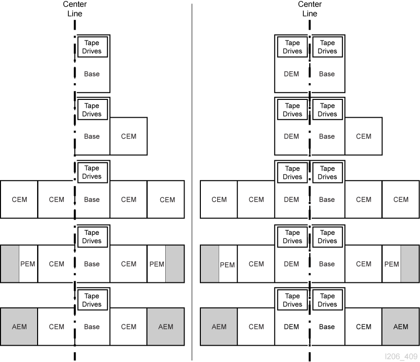
Internal firmware and HLI addressing use the center line of the library as a reference point. When you add modules to either end of the library, the existing components do not change address number.
Figure E-1 shows the location of the centerline for various library configurations.
Internal Firmware Addressing Scheme
Internal Firmware Addressing Overview
Internal firmware addressing designates physical location using Library, Rail, Column, Side, Row (L,R,C,S,W).
- Library
-
Always equal to 1.
- Rail
-
Always equal to 1.
- Column
-
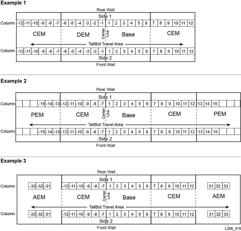
Indicates the horizontal location of a cartridge or drive referenced from the center line (see "Understanding the Center Line").
-
Positive (+) value indicates right of center line
-
Negative (-) value indicates left of center line
Base Module
-
Contains columns 1 to 6 for data cartridges and 1 to 4 for tape drives.
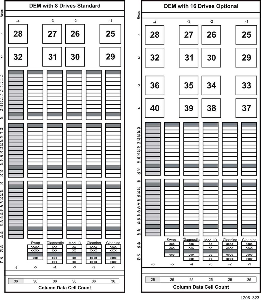
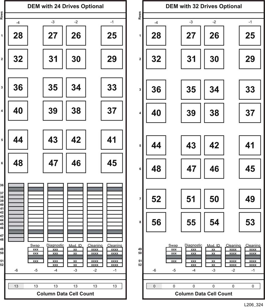
DEM
-
Contains columns -1 to -6 for data cartridges and -1 to -4 for tape drives.
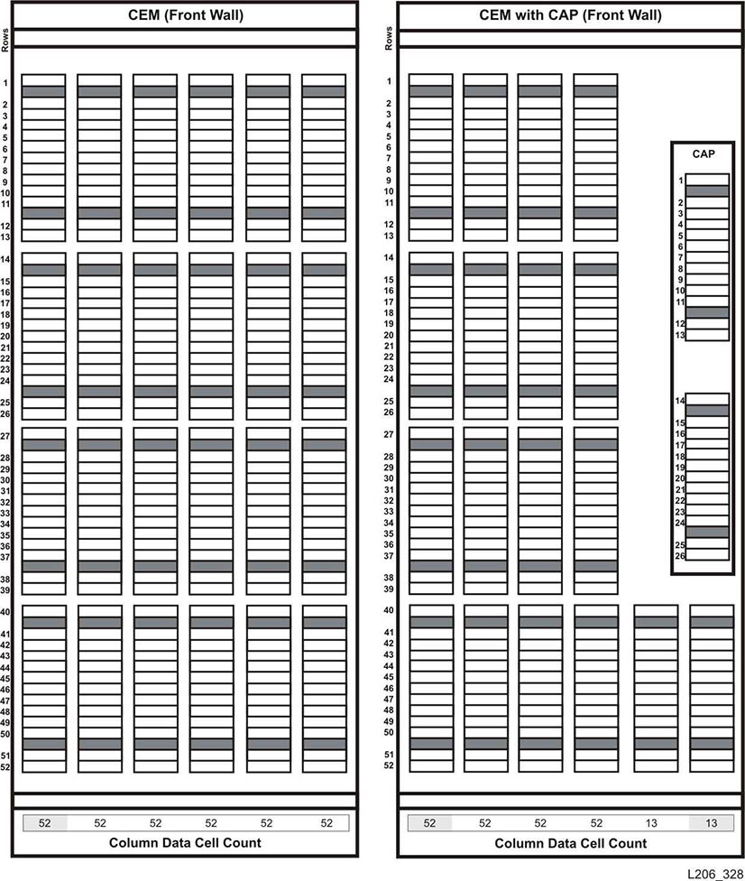
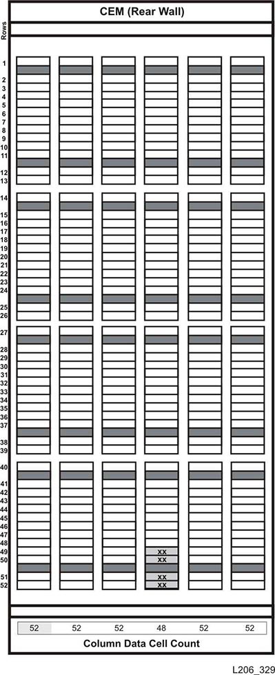
CEM
-
Contains six columns for data cartridges.
-
Column numbering continues consecutively from the adjacent module. However, if there is no DEM, a CEM placed directly to the left of a Base contains columns -7 to -12 (columns -1 to -6 are skipped).
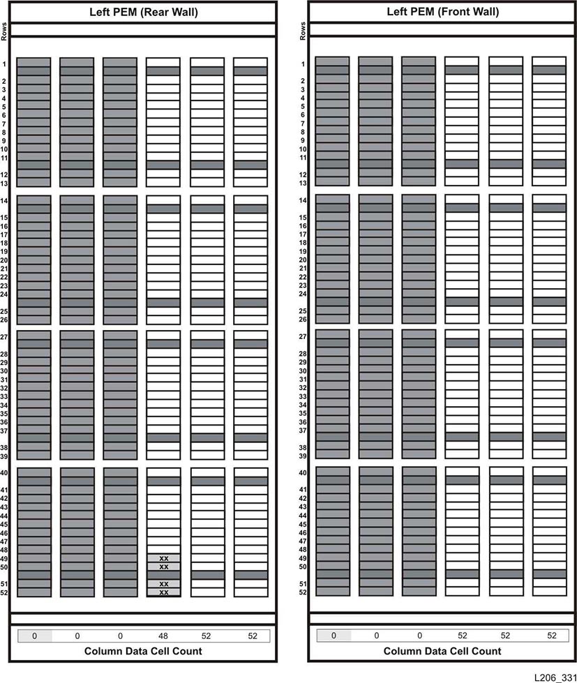
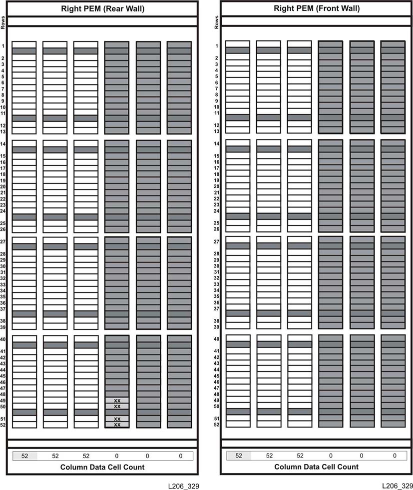
PEM
-
Contains only three columns for data cartridges. The outer most three columns are inactive.
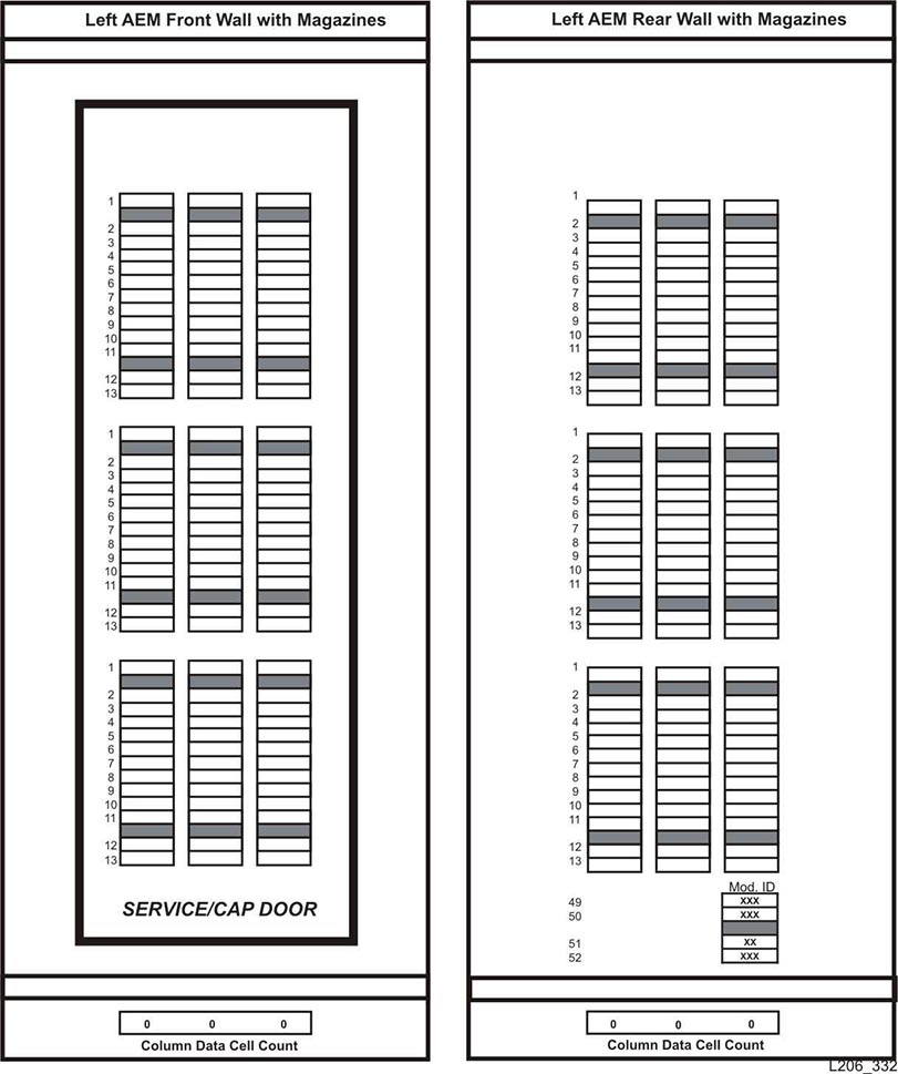
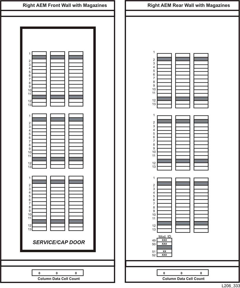
AEM
-
AEM columns are numbered as if a DEM and four CEMS are installed to the left of the Base Module and four CEMs are installed to the right.
-
Left AEM columns are always numbered -33 to -31.
-
Right AEM columns are always 31 to 33.
-
- Side
-
Indicates the front wall (CAP side) or rear wall (drive side) of the library.
-
Rear wall = 1
-
Front wall = 2
-
- Row
-
The vertical location of a tape cartridge, consecutively numbered from the top (1) down (52).
Internal Firmware Addressing of Tape Drives
The firmware addressing (library, rail, column, side, row) distinguishes a drive based on column and row. The library, rail, and side values are always equal to 1.
Note:
The perspective in Figure E-3 is from the drive-side (rear) of the library.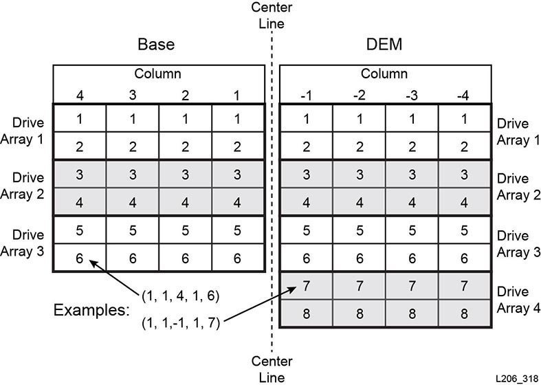
Internal Firmware Addressing of Robots
- Column
-
The column value is always 0.
- Side
-
If there is only one robot: the side value is always 1.
For redundant robot configurations:
-
Left robot = 1
-
Right robot = 2
-
- Row
-
When addressing the device: the row is 0.
When addressing the specific slot: the row is the slot value (1).
- Example - Robot Firmware Addressing
-
For this example, the address is referring to the right robot in a redundant robotics library.
The firmware address is: (1, 1, 0, 2, 0)
Internal Firmware Addressing of CAPs
Rotational CAP Addressing
- Column
-
The column value depends on the size of the library and the location of the module that contains the CAP.
For modules to the left of centerline, the CAP column value corresponds to the second column from the right of the module. For example, in a DEM, the column value for the CAP would be -2 and a CEM to the left of the DEM would have a CAP column value of -8.
For modules to the right of centerline, the CAP column value corresponds to the fifth column from the left of the module. For example, a CAP in the Base has a column value of 5 and a CEM to the right of the Base would have a CAP column value of 11.
- Side
-
The side value is always 2, since the CAPs are only located on the front of the module.
- Row
-
When addressing the device: the row value is 0.
When addressing a specific slot: the row value is the slot in the CAP magazine (values 1 to 26).
- Example - Rotational Firmware Addressing
-
For this example, the library has a Base, DEM, and four CEMs (two on each side). The address refers to the sixth slot down in the CAP in the CEM on the far left.
The firmware address is: (1, 1, -14, 2, 6)
AEM CAP Addressing
- Column
-
The column value when referencing the CAP is:
-
-31 for left AEM
-
31 for right AEM
The column value when referencing a slot in the CAP:
-
-31 to -33 for left AEM
-
31 to 33 for right AEM
-
- Side
-
Indicates the front or rear CAP doors on the library.
-
Rear wall = 1
-
Front wall = 2
-
- Row
-
When addressing the device: the row value is 0.
When addressing a specific slot: the row value is the slot in the CAP (values 1 to 26).
- Example - AEM CAP Firmware Addressing
-
For this example, the address is referencing a cartridge slot in the right AEM. The slot is the 37th down in the far right column in the rear CAP door.
The firmware address is: (1, 1, 33, 1, 37)
HLI-PRC Addressing Scheme
HLI Addressing Overview
HLI-PRC addressing designates physical location using: LSM, Panel, Row, and Column.
- LSM
-
Always equal to 0.
- Panel
-
Indicates the front wall (CAP side) or rear wall (drive side) of a module. The panel number can range from 0 to 23 depending on the configuration of the library.
-
Rear wall = even numbers
-
Front wall = odd numbers
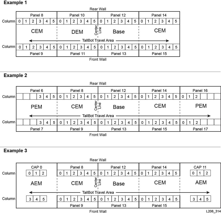
The panel location is defined relative to the Base Module (panels 12 and 13). Panel values less than 12 indicate the module is to the left of the Base Module, while values greater than 13 indicate the module is to the right of the Base Module.
Base Module
-
Panels 12 and 13
DEM
-
Panels 10 and 11
CEM
-
Panels are numbered consecutively from the adjacent module. However, if there is no DEM, a CEM placed directly to the left of a Base Module contains panels -8 and -9 (panels -10 and -11 are skipped).
AEM
-
AEMs are considered CAPs by HLI addressing. Therefore, AEMs have a CAP ID instead of a panel number (see "HLI Addressing of CAPs")
-
Left AEM CAP ID is always numbered 0
-
Right AEM CAP ID is always numbered 11
-
- Row
-
The vertical location of a slot, consecutively numbered from the top down (0 to 51). However, drive bays have row numbering from 0 to 23 for the Base Module, and 0 to 31 in the DEM.
- Column
-
The horizontal location of a slot from left to right (0 to 5). However, drive bays always have a column value of 0 (see "Tape Drive Hardware Numbering"").
AEM column numbering starts at the rear wall and runs left to right (columns 0–2), then proceeds to the front wall and runs left to right (columns 3–5).
HLI Addressing of CAPs
HLI addressing defines CAP locations with a CAP ID instead of a panel value. The addressing is LSM, CAP ID, row, column.
Rotational CAP Addressing
- LSM
-
Always equal to 0.
- CAP ID
-
Ranges from 1 to 10
-
CEMs left of centerline = 1 to 4 (left to right)
-
DEM = 5
-
Base Module = 6
-
CEMs right of centerline = 6 to 10 (left to right)
-
- Row
-
The value is the slot in the CAP (can be values 0 to 25).
- Column
-
The value always equals 0.
- Example - Rotational CAP HLI Addressing
-
For this example, the library has a Base, DEM, and eight CEMs (four on each side). The address refers to the sixth slot down in the CAP in the CEM on the far left.
The HLI address is: (0, 1, 5, 0)
AEM CAP Addressing
- LSM
-
Always equal to 0.
- CAP ID
-
Left AEM equals 0.
Right AEM equals 11.
- Row
-
The value is the slot in a column (can be values 0 to 38).
- Column
-
Rear wall = columns 0 to2
Front wall = columns 3 to 5
HLI Addressing of Tape Drives
HLI addressing defines tape drives with a drive ID instead of a row value. The addressing is LSM, panel, drive ID, column (see "Tape Drive Hardware Numbering"). HLI distinguishes a drive based on the panel and drive value. The LSM and column values are always equal to 0.
Note:
The perspective in Figure E-5 is from the drive-side (rear) of the library.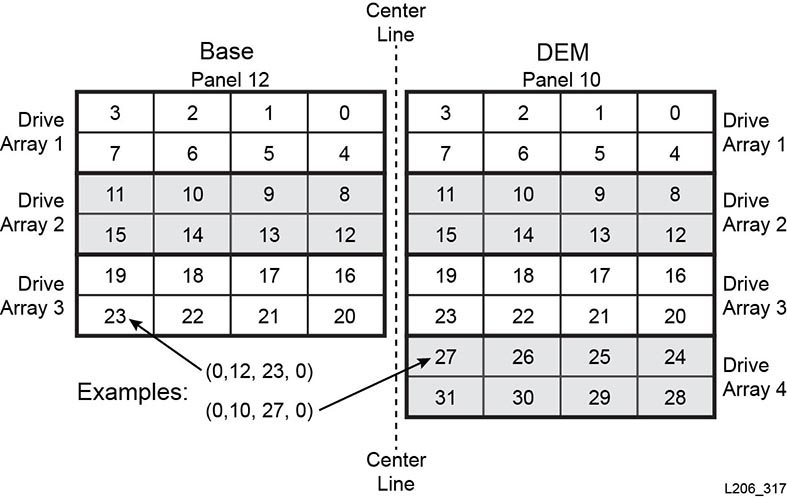
FC-SCSI Element Numbering
Note:
Changing the library configuration can cause the library to re-assign element numbers.For FC-SCSI element numbering, each active component in the library has a unique element ID. SCSI element numbering consists of three element types:
-
Storage Elements (active storage slots)
-
Begins at 2000.
-
Numbered top to bottom, left to right, and rear to front.
-
-
Import/Export Elements (rotational CAPs)
-
Begins at 10 for the left most CAP in the library. Storage and Import/Export elements are numbered sequentially by slot. No slots are skipped.
-
Numbered top to bottom, left to right (see Figure E-9)
-
-
Data Transfer Elements (drives)
-
Begins at 1000 and increments by one for every installed drive.
-
Numbered left to right, top to bottom, starting at the center line in the base module and continuing in the DEM if installed.
Note:
When the library powers on, a vacant drive slot will not be included in the element number sequence. Open Systems backup applications do not tolerate Data Transfer Elements that cannot or do not respond when you power-on the library.
-
Default SCSI Numbering
Note:
The default numbering pattern assumes you have a non-partitioned library using the default "left to right" capacity configuration.Default SCSI Storage Element (Cartridges) Numbering Scheme
-
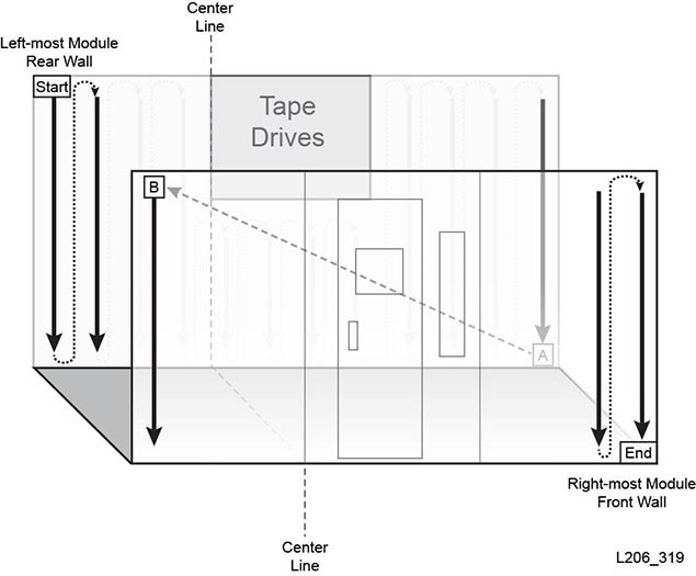
The numbering starts at 2000 in the upper left slot on the rear wall of the left-most module.
-
The numbering increases from top to bottom and left to right.
-
When the numbering reaches the last slot on the rear wall, it crosses to the front wall of the left-most module (A to B in Figure E-6).
-
The numbering continues top to bottom, left to right, and ends at the lower right slot of the right-most module.
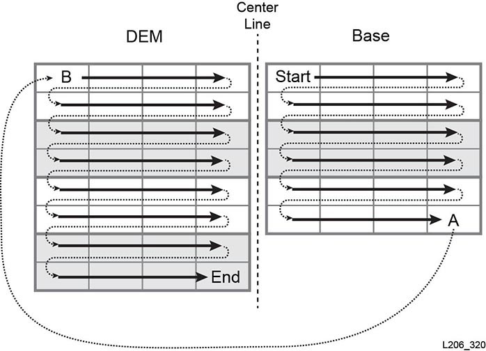
Default SCSI Data Transfer Element (Drives) Numbering Scheme
-
The numbering starts in the upper left drive slot in the Base Module.
-
The numbering increases from left to right and top to bottom (skipping any empty drive slots).
-
When the numbering reaches the lower right drive slot on the Base Module, it crosses to the Drive Expansion Module (A to B in Figure E-7).
-
The numbering continues left to right, top to bottom, and ends at the lower right slot of the DEM.
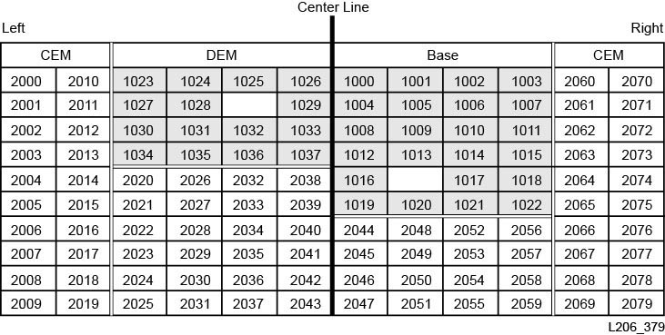
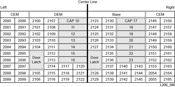
Default Numbering Example
Note:
The library in this example has been simplified. It is not an exact representation of an SL3000.The example library includes:
-
Four modules: one Base, one DEM, and two CEMs
-
166 data cartridge slots: numbered 2000 to 2165
-
40 tape drive bays (two tape drives are missing, one in each module): numbered 1000 to 1037
-
Two CAPs, each with seven slots: numbered 10 to 23
The default numbering is shown in the figures below.
SCSI Numbering in Non-Partitioned Library Using Custom Capacity
After activating an area of the library, the numbering begins with the left most slot on the rear wall within the active area. Then, the numbering scheme follows the pattern defined in "Default SCSI Storage Element (Cartridges) Numbering Scheme" for all active slots, but skips over any inactive slots.
When you activate additional capacity later, the SCSI numbering of previously activated slots does not change. The library appends the SCSI numbering for newly activated slots.
If you add tapes drives, the library reassigns SCSI Data Transfer element numbering following the "Default SCSI Data Transfer Element (Drives) Numbering Scheme". Then, the library restarts.
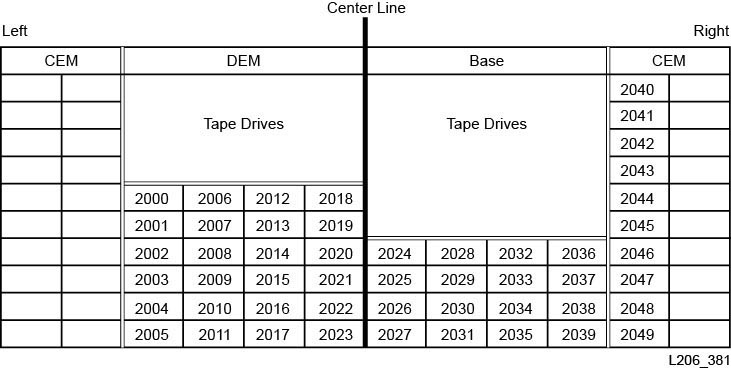
Custom Capacity Numbering Example
Note:
The library in this example has been simplified. It is not an exact representation of an SL3000.For this example, the user activates 50 slots, beginning with the DEM. As a result, the SCSI storage element numbering begins at 2000 with the upper left-most active slot in the DEM (see Figure E-10 below).
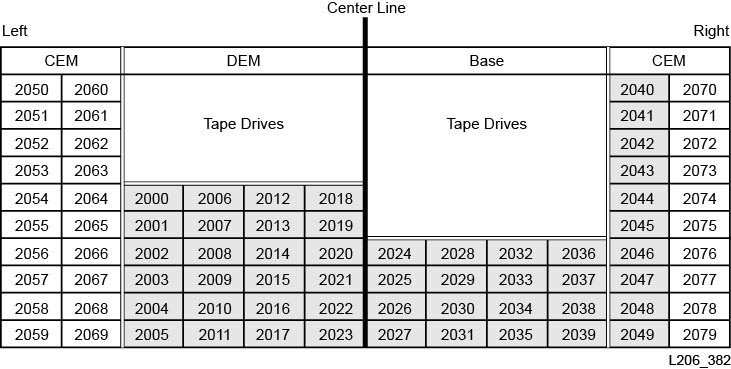
At a later date, the user activates the remaining 30 slots in the library. The library numbers the slots starting with 2050 in the upper left corner of the CEM (see Figure E-11 below).
SCSI Numbering in a Partitioned Library
When you define a partition, the numbering begins with the left most slot on the rear wall within the partition. The numbering scheme follows the pattern defined in "Default SCSI Storage Element (Cartridges) Numbering Scheme" for all active slots, but skips over any inactive slots and slots not within the partition. Therefore, element numbering is continuous within each partition, even if slot locations for the partition are not adjacent.
If you allocate more resources to the partition, the SCSI numbering of previously numbered elements in the partition do not change. The library simply appends the SCSI numbering for newly activated slots or newly inserted tape drives within the partition.
Tape Drive Hardware Numbering
The hardware numbering is assigned by the HBC controller card. It is used to identify a tape drive slot. The card automatically assigns a number, 1-56, to each drive slot.
Note:
The perspective in Figure E-12 is from the drive-side (rear) of the library.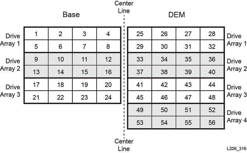
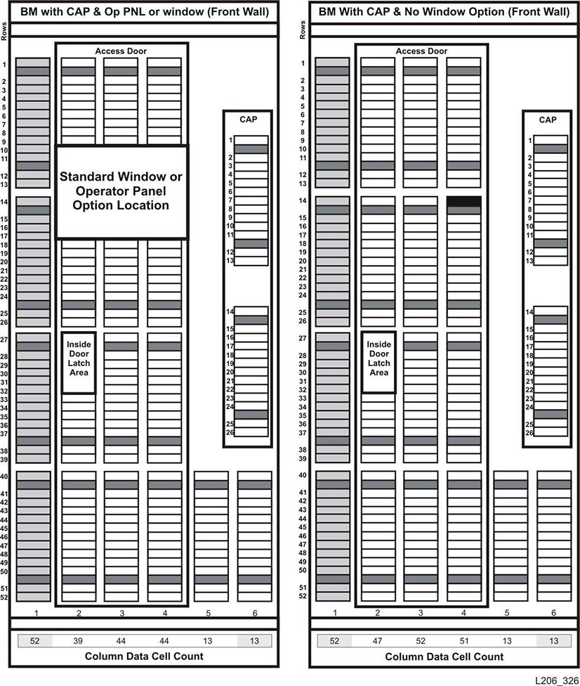
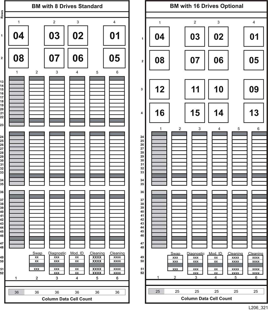
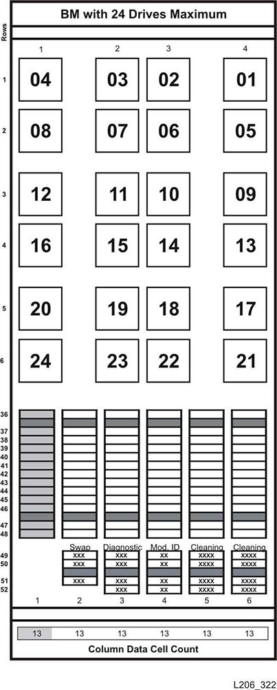
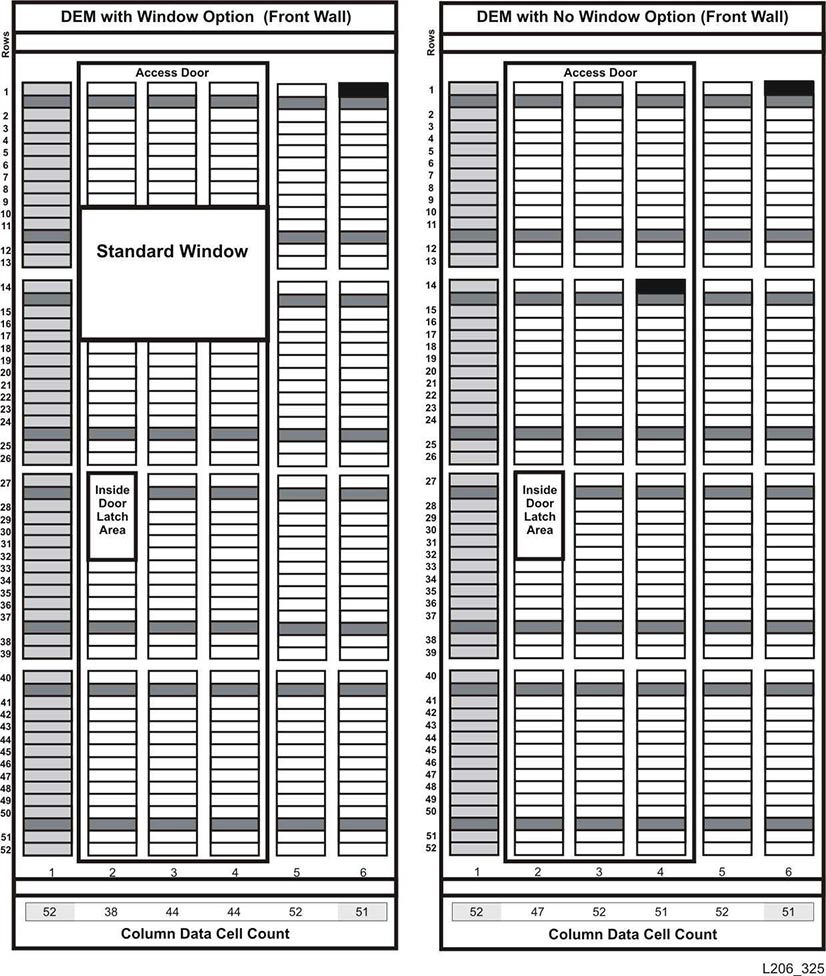
Wall Diagrams
-
Base Module front wall (Figure E-13)
-
Base Module rear wall (Figure E-14 and Figure E-15)
-
DEM front wall (Figure E-16 and Figure E-17)
-
DEM rear wall (Figure E-18 and Figure E-19)
-
CEM front wall (Figure E-20)
-
CEM rear wall (Figure E-21)
-
Left PEM (Figure E-22)
-
Right PEM (Figure E-23)
-
Left AEM (Figure E-24)
-
Right AEM (Figure E-25)