| Oracle® Communications IP Service Activator Juniper M-series Device Support Guide Release 7.2 E47718-01 |
|
|
PDF · Mobi · ePub |
| Oracle® Communications IP Service Activator Juniper M-series Device Support Guide Release 7.2 E47718-01 |
|
|
PDF · Mobi · ePub |
This appendix provides example configuration of the routers involved in an MPLS-VPN.
The network associated with the sample configuration files is shown in Figure A-1.
Note the following points:
A management VPN is set up comprising the Management site and all other sites. With Oracle Communications IP Service Activator running at the management site, all CE routers can be managed.
Customer VPN 1 comprises sites 1, 2 and 4.
Customer VPN 2 comprises sites 1, 3 and 5.
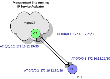
In order to configure the management VPN, two links are required between the management site and the core network, one to provide VPN connectivity and one to provide routes to the Service Provider backbone IGP. Figure A-2 illustrates these two links.
Figure A-2 Dual Links Between Management Site and Core Network

The interfaces at both ends of the ATM 0.1 link between PE1 and mgmtCE (the link that is not to be used for the VPN connection) must be assigned a role of Disabled within IP Service Activator to prevent them being configured into a VPN.
Note:
For details of the steps required to set up management and customer VPNs, see IP Service Activator VPN User's Guide.