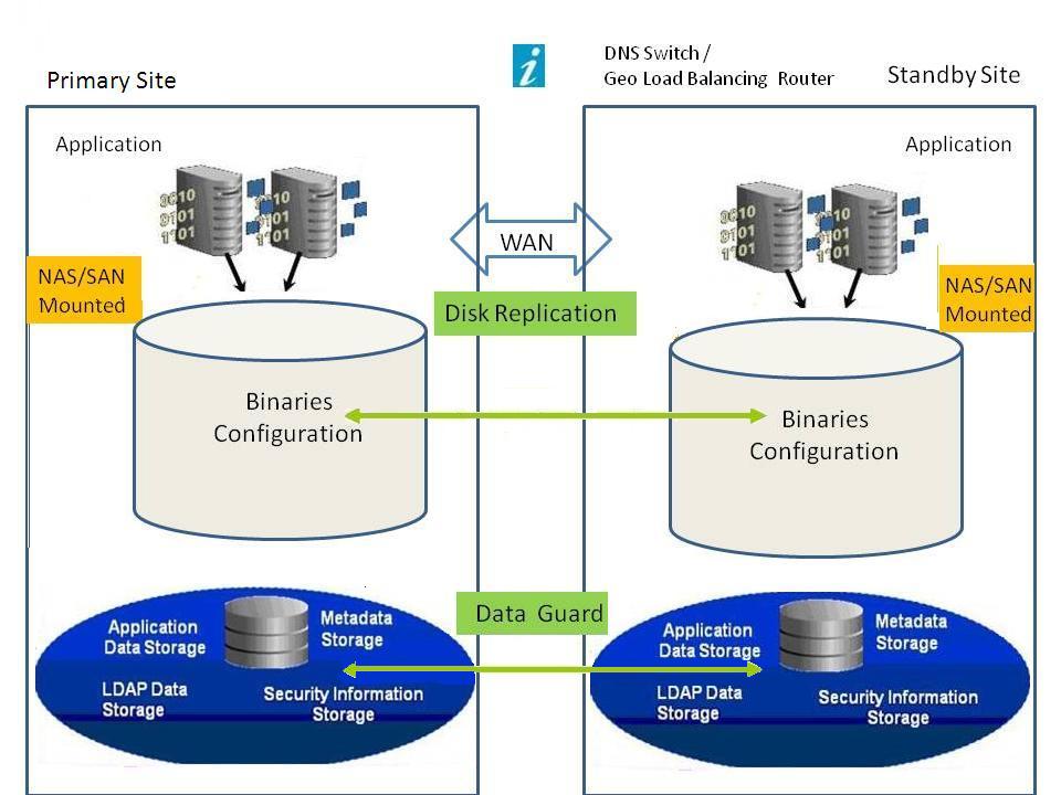
Note: | Although the deployment shown in Figure 1, EPM System Disaster Recovery Architecture uses symmetric topology, with the same number of servers at the production and standby sites, deployment using asymmetric topology (with fewer servers at the standby site than at the production site) is also possible. Deployment with asymmetric topology requires a server at the standby site for each logical server cluster at the production site. Use of a shared or replicated disk requires a common share across machines; for example, the share can be under /user_projects/data. |