F VSM4 ESCON Configuration
VSM4 provides the following advantages over its predecessors:
-
Enhanced connectivity options
-
Greater throughput
-
Greater VTSS capacity
-
4x the number of VTDs and 3x the maximum number of VTVs per VTSS
-
Improved reliability and serviceability
Table F-1 summarizes the VSM3 to VSM4 ESCON enhancements that you see from a software and system configuration perspective.
Table F-1 VSM3 to VSM4 Comparison: Software and System Configuration ESCON Enhancements
| Product Feature | VSM3 | VSM4 |
|---|---|---|
|
ESCON Interfaces |
16 total where:
|
32 total where:
Note: VSM4s are shipped with 16 ports enabled.With the 16 ports enabled option, only the top port on each CIP is enabled (Port 0 or Port 2). 32 ports enabled is an optional, separately priced feature that is activated through the microcode diskette. On a VSM4 with 32 ports enabled, each ICE3 ESCON interface card contains two pairs of ESCON ports. |
|
Maximum Logical Paths |
128 |
16 per port for the 16 port standard configuration = 256 logical paths 16 per port for the 32 port optional configuration= 512 logical paths Note: VSM4 provides a theoretical maximum of 512 logical paths per VTSS but you cannot allocate all 512 logical paths for host-to-VTSS connections. |
|
VTDs per VTSS |
64 |
256 |
|
Maximum resident VTVs per VTSS |
100,000 |
300,000 |
VSM4 with 32 Ports
For the 32 port option, the 8 ICE3 cards have four ESCON ports per card as shown in Figure F-1.
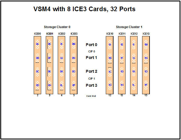
Note:
In Figure F-1 and all the other figures in this appendix, the ports are shown with their channel interface identifiers for enabled ports (32 in Figure F-1). These channel interface identifiers are the values that are required for the CHANIF values that you code for the CONFIG utility. Each value is two characters in length and has a value from 0A to 1P. The first digit is the VTSS cluster ID (valid values are 0 or 1). The second digit is the group or adapter ID (valid values are A to P).In Figure F-1, note the following:
-
Each ICE3 card contains two pairs of ESCON ports. Each pair is controlled by its own Channel Interface Processor (CIP).
-
With microcode level D02.06.00.00 or higher, multiple Nearlink device connections using an ESCON switch or Director on the same port now allow:
-
Up to a total of 16 simultaneous NearLink I/O transfers, which can be spread across multiple targets on as many as 14 NearLink ports.
-
Up to a total of 2 simultaneous NearLink I/O transfers are allowed per port.
-
-
For a VSM4, each CIP can operate with only one of two modes, which is set at the VTSS LOP:
-
Host Mode. In Host Mode, either or both ESCON ports can connect to host CPU channels, including through ESCON Director(s) or channel extenders. Ports of a CIP in Host mode cannot connect to RTDs or to Secondary VTSSs using CLINKS. Note, however, that Secondary VTSSs must have an ESCON port in Host Mode to connect using a CLINK from an ESCON port in Nearlink Mode in a Primary VTSS.
Also note that you can have two physical paths from the same LPAR to the same CIP, as long as the two physical paths address different (not overlapping) logical control units. For example, a single host LPAR can address logical control units 0-7 on one CIP port, and 8-F on the other CIP port of the same CIP.
-
Nearlink Mode. In Nearlink Mode, either or both ESCON ports can connect to an RTD or using a CLINK to a Secondary VTSS. Ports of a CIP in Nearlink mode cannot connect to host CPU channels.You can set a maximum of 8 CIPs to Nearlink Mode, and here's the important discussion: only one Nearlink port per CIP is active at one time.
Table F-2 shows best practices for optimizing port operations.
Table F-2 Optimizing VSM4 Port Operations
Configuration - Two Ports on a CIP Best Practices Two CLINKs
Attach a maximum of 2 because each port allows two active operations. Note, however, that these operations share the bandwidth of the port.
CLINK and RTD
An advantage if you attach one CLINK originator/one RTD per director, because both can be active.
Two RTDs
An advantage for the following:
-
Optimize use of local and remote RTDs. During busy shifts, use only local RTDs on the FIP. During quiet periods, switch to remote RTDs for deep archive and DR work. Because you can have two active devices, you can also simultaneously run one local and one remote RTD. Note, however, that these operations share the bandwidth of the port.
-
Optimize use of different drive technologies. As described in the previous bullet, use a T9840 as a local RTD, then switch to a T9940 for deep archive. You can also use this feature to migrate from older drive technology (such as 9490) to newer technology (such as 9840). Use Management and Storage Classes to read in data from older media, then switch to the newer technology drive to place data on new media. This technique effectively gives you greater physical connectivity to different drive technologies without incurring the overhead of full time, real time FICON connections to each drive type. Also as above, because you can have two active devices, you can also simultaneously run two RTDs with different drive technologies. Note, however, that these operations share the bandwidth of the port.
-
-
-
On a VSM4 with 32 ports enabled, you have a theoretical maximum of 512 logical paths on the VSM4. However, you must have some RTD connections so you cannot allocate all 512 logical paths for host-to-VTSS connections. The minimum number of RTDs is determined by a couple factors:
-
CONFIG will not allow fewer than 2 RTDS per VTSS.
-
CONFIG cannot check the device type but Oracle strongly recommends at least two RTDS of each device type in each ACS to which the VTSS is attached. Otherwise, you can seriously compromise error recovery, and also impact the efficiency of space reclamation.
If you have only two RTDs, Best Practices suggest that you connect them to different ICE3 cards. Once you have done that, you have effectively used up 4 Nearlink ports due to the CIP mode nature of the ICE3 card. Therefore, in an 8 ICE card configuration, this leaves 28 available ports for host-to-VTSS ESCON channel connections, which equals a maximum of 16 x 28 (448) logical paths. For more information, see "Logical Paths for VSM 4 with 32 Ports."
-
-
A host logical path is the communication path between a host and all of the 256 VTDs within the VSM4. Table F-3 summarizes the configuration options and maximum host logical paths for a VSM4 with 32 enabled ports.
-
In HCD:
-
From a single MVS host, you can only define 8 channels (CHPIDs) running to a single control unit (single VSM4). Also note that ICE3 cards cannot have 2 paths from the same LPAR connected to two ports with a common CIP.
-
You use the CNTLUNIT statement to define each VSM4 as 16 3490 images.
-
You use the IODEVICE statement to define the 16 VTDs that are associated with each 3490 image.
-
VSM4 Configuration Examples - 32 Ports
For VSM4s with 32 ports, look at two examples of port configurations:
For a VSM4 host gen example, see "IOCP Example for Single MVS Host Connected to a VSM4 Using ESCON Directors."
VSM4 Configuration Example: 16 Host Ports, 16 RTD Ports
Figure F-2 shows CONFIG channel interface identifiers of 16 for hosts, 16 for RTDs for a VSM4.
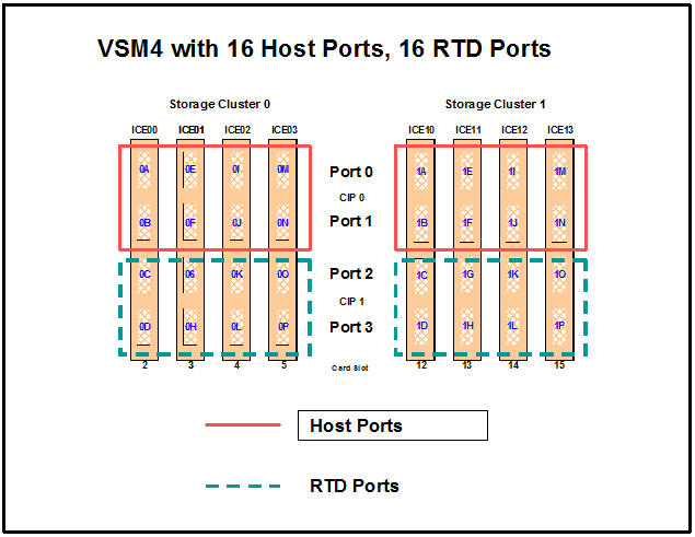
CONFIG Example for VSM4 with 16 Host Ports, 16 RTD Ports
//CREATECF EXEC PGM=SLUADMIN,PARM='MIXED'
//STEPLIB DD DSN=hlq.SEALINK,DISP=SHR
//SLSCNTL DD DSN=hlq.DBASEPRM,DISP=SHR
//SLSCNTL2 DD DSN=hlq.DBASESEC,DISP=SHR
//SLSSTBY DD DSN=hlq.DBASETBY,DISP=SHR
//SLSPRINT DD   SYSOUT=*
//SLSIN DD   *
CONFIG
 GLOBAL MAXVTV=32000 MVCFREE=40
 RECLAIM THRESHLD=70 MAXMVC=40  START=35
VTSS NAME=VSM401 LOW=70 HIGH=80 MAXMIG=8 RETAIN=5
 RTD  NAME=VSM42A02 DEVNO=2A02 CHANIF=0G
 RTD  NAME=VSM42A04 DEVNO=2A04 CHANIF=0K
 RTD  NAME=VSM42A06 DEVNO=2A06 CHANIF=0O
 RTD  NAME=VSM42A0A DEVNO=2A0A CHANIF=1G
 RTD  NAME=VSM42A0C DEVNO=2A0C CHANIF=1K
 RTD  NAME=VSM42A0E DEVNO=2A0E CHANIF=1O
 VTD LOW=9900 HIGH=99FF
VSM 4 Configuration Example: 20 Host Ports, 12 RTD Ports
Figure F-3 shows port assignments of 20 for hosts, 12 for RTDs for a VSM4.
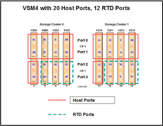
CONFIG Example for VSM4 with 20 Host Ports, 12 RTD Ports
//CREATECF EXEC PGM=SLUADMIN,PARM='MIXED'
//STEPLIB DD DSN=hlq.SEALINK,DISP=SHR
//SLSCNTL DD DSN=hlq.DBASEPRM,DISP=SHR
//SLSCNTL2 DD DSN=hlq.DBASESEC,DISP=SHR
//SLSSTBY DD DSN=hlq.DBASETBY,DISP=SHR
//SLSPRINT DD   SYSOUT=*
//SLSIN DD   *
CONFIG
 GLOBAL MAXVTV=32000 MVCFREE=40
 RECLAIM THRESHLD=70 MAXMVC=40  START=35
VTSS NAME=VSM401 LOW=70 HIGH=80 MAXMIG=6 RETAIN=5
 RTD  NAME=VSM42A00 DEVNO=2A00 CHANIF=0G
 RTD  NAME=VSM42A01 DEVNO=2A01 CHANIF=0H
 RTD  NAME=VSM42A02 DEVNO=2A02 CHANIF=0K
 RTD  NAME=VSM42A03 DEVNO=2A03 CHANIF=0L
 RTD  NAME=VSM42A04 DEVNO=2A04 CHANIF=0O
 RTD  NAME=VSM42A05 DEVNO=2A05 CHANIF=0P
 RTD  NAME=VSM42A06 DEVNO=2A06 CHANIF=1G
 RTD  NAME=VSM42A07 DEVNO=2A07 CHANIF=1H
 RTD  NAME=VSM42A08 DEVNO=2A08 CHANIF=1K
 RTD  NAME=VSM42A09 DEVNO=2A09 CHANIF=1L
 RTD  NAME=VSM42A0A DEVNO=2A0A CHANIF=1O
 RTD  NAME=VSM42A0B DEVNO=2A0B CHANIF=1P
 VTD LOW=9900 HIGH=99FF
VSM4 with 16 Ports
For the 16 port option, the 8 ICE3 cards have two ESCON ports per card as shown in Figure F-4.
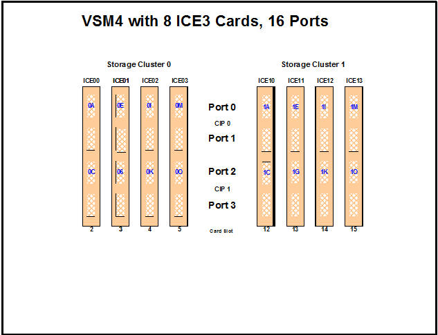
Note:
In Figure F-4 and all the other figures in this appendix, the ports are shown with their channel interface identifiers for enabled ports (16 in Figure F-4). These channel interface identifiers are the values that are required for the CHANIF values that you code for the CONFIG utility. Each value is two characters in length and has a value from 0A to 1P. The first digit is the VTSS cluster ID (valid values are 0 or 1). The second digit is the group or adapter ID (valid values are A to P).In Figure F-4, note the following:
-
Each ICE3 card has two CIPs with a single port enabled on each CIP. As with the 32 port option, each CIP can operate with only one of two modes, which is set at the VTSS LOP:
-
Host Mode. In Host Mode, the single ESCON port can connect to host CPU channels, including through ESCON Director(s) or channel extenders. Ports of a CIP in Host mode cannot connect to RTDs or to Secondary VTSSs using CLINKS. Note, however, that Secondary VTSSs must have an ESCON port in Host Mode to connect through a CLINK from an ESCON port in Nearlink Mode in a Primary VTSS.
-
Nearlink Mode. In Nearlink Mode, the single ESCON port can connect to an RTD or through a CLINK to a Secondary VTSS. Ports of a CIP in Nearlink mode cannot connect to host CPU channels.
You can set a maximum of 8 CIPs to Nearlink Mode. Therefore, in a 16 port configuration, the single port on a CIP can be either a CLINK or an RTD connection.
-
-
On a VSM4 with 16 ports enabled, you have a theoretical maximum of 256 logical paths on the VSM4. However, you must have some RTD connections so you cannot allocate all 256 logical paths for host-to-VTSS connections.
What is the minimum number of RTDs?
-
CONFIG will not allow fewer than 2 RTDS per VTSS.
-
CONFIG cannot check device type but Oracle strongly recommends at least two RTDS of each device type in each ACS to which the VTSS is attached. Otherwise, you can seriously compromise error recovery and also impact the efficiency of space reclamation. If you had only two RTDs, Best Practices would suggest that you connect them to different ICE3 cards. Once you have done that, you have effectively used up 4 Nearlink ports. Therefore, in an 8 ICE card 16 port configuration, this leaves 12 available ports for host-to-VTSS ESCON channel connections, which equals a maximum of 16 x 12 or 192 logical paths. For more information, see "Logical Paths for VSM 4 with 32 Ports."
-
-
A host logical path is the communication path between a host and all of the 256 VTDs within the VSM4. Table F-4 summarizes the configuration options and maximum host logical paths for a VSM4 with 16 enabled ports.
-
In HCD:
-
From a single MVS host, you can only define 8 channels (CHPIDs) running to a single control unit (single VSM4). Also note that ICE3 cards cannot have 2 paths from the same LPAR connected to two ports with a common CIP.
-
You use the CNTLUNIT statement to define each VSM4 as 16 3490 images.
-
You use the IODEVICE statement to define the 16 VTDs that are associated with each 3490 image.
-
VSM4 Configuration Examples - 16 Ports
For VSM4s with 16 ports, look at two examples of port configurations:
For a VSM4 host gen example, see "IOCP Example for Single MVS Host Connected to a VSM4 Using ESCON Directors."
VSM4 Configuration Example: 8 Host Ports, 8 RTD Ports
Figure F-5 shows CONFIG channel interface identifiers of 8 for hosts, 8 for RTDs for an 8 ICE3 card VSM4 with 16 ports.
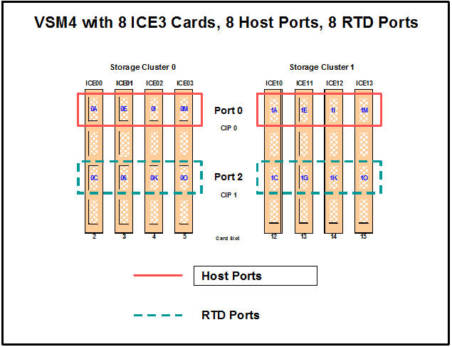
CONFIG Example for VSM4 with 8 Host Ports, 8 RTD Ports
The following example shows CONFIG JCL to define the VSM4 configuration shown in Figure F-5.
//CREATECF EXEC PGM=SLUADMIN,PARM='MIXED'
//STEPLIB DD DSN=hlq.SEALINK,DISP=SHR
//SLSCNTL DD DSN=hlq.DBASEPRM,DISP=SHR
//SLSCNTL2 DD DSN=hlq.DBASESEC,DISP=SHR
//SLSSTBY DD DSN=hlq.DBASETBY,DISP=SHR
//SLSPRINT DD   SYSOUT=*
//SLSIN DD   *
CONFIG
 GLOBAL MAXVTV=32000 MVCFREE=40
 RECLAIM THRESHLD=70 MAXMVC=40  START=35
VTSS NAME=VSM401 LOW=70 HIGH=80 MAXMIG=8 RETAIN=5
 RTD  NAME=VSM42A00 DEVNO=2A00 CHANIF=0C
 RTD  NAME=VSM42A02 DEVNO=2A02 CHANIF=0G
 RTD  NAME=VSM42A04 DEVNO=2A04 CHANIF=0K
 RTD  NAME=VSM42A06 DEVNO=2A06 CHANIF=0O
 RTD  NAME=VSM42A08 DEVNO=2A08 CHANIF=1C
 RTD  NAME=VSM42A0A DEVNO=2A0A CHANIF=1G
 RTD  NAME=VSM42A0C DEVNO=2A0C CHANIF=1K
 RTD  NAME=VSM42A0E DEVNO=2A0E CHANIF=1O VTD LOW=9900 HIGH=99FF
VSM 4 Configuration Example: 10 Host Ports, 6 RTD Ports
Figure F-6 shows port assignments of 10 for hosts, 6 for RTDs for a VSM4 with 16 ports.
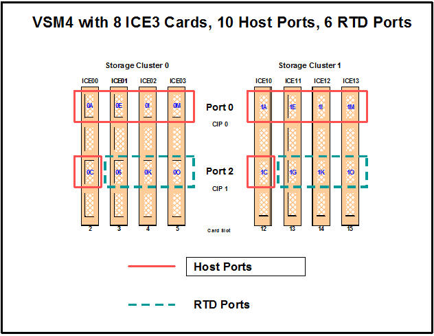
CONFIG Example for VSM4 with 10 Host Ports, 6 RTD Ports
The following example shows CONFIG JCL to define the VSM4 configuration shown in Figure F-6.
//CREATECF EXEC PGM=SLUADMIN,PARM='MIXED'
//STEPLIB DD DSN=hlq.SEALINK,DISP=SHR
//SLSCNTL DD DSN=hlq.DBASEPRM,DISP=SHR
//SLSCNTL2 DD DSN=hlq.DBASESEC,DISP=SHR
//SLSSTBY DD DSN=hlq.DBASETBY,DISP=SHR
//SLSPRINT DD   SYSOUT=*
//SLSIN DD   *
CONFIG
 GLOBAL MAXVTV=32000 MVCFREE=40
 RECLAIM THRESHLD=70 MAXMVC=40  START=35
VTSS NAME=VSM401 LOW=70 HIGH=80 MAXMIG=8 RETAIN=5
 RTD  NAME=VSM42A02 DEVNO=2A02 CHANIF=0G
 RTD  NAME=VSM42A04 DEVNO=2A04 CHANIF=0K
 RTD  NAME=VSM42A06 DEVNO=2A06 CHANIF=0O
 RTD  NAME=VSM42A0A DEVNO=2A0A CHANIF=1G
 RTD  NAME=VSM42A0C DEVNO=2A0C CHANIF=1K
 RTD  NAME=VSM42A0E DEVNO=2A0E CHANIF=1O
 VTD LOW=9900 HIGH=99FF
IOCP Example for Single MVS Host Connected to a VSM4 Using ESCON Directors
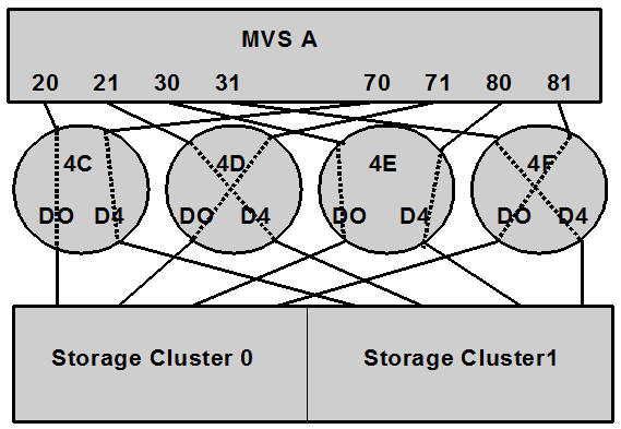
Figure F-7 shows a configuration diagram for a single MVS host connected to a VSM4 using ESCON Directors, and the example following it contains IOCP statements for this configuration. Note that:
-
From MVSA, you define 8 CHPIDs, with each path switched in the ESCON Director, for a total of 8 channels running to the VSM4.
-
You code 16 CNTLUNIT statements to define the VSM4 as 16 3490 images.
-
You code IODEVICE statement to define the 16 VTDs that are associated with each 3490 image.
ESCD4C CHPID PATH=(20,70),TYPE=CNC,SWITCH=4C
ESCD4D CHPID PATH=(21,71),TYPE=CNC,SWITCH=4D
ESCD4E CHPID PATH=(30,80),TYPE=CNC,SWITCH=4E
ESCD4F CHPID PATH=(31,81),TYPE=CNC,SWITCH=4F

CU1 CNTLUNIT CUNUMBR=001,
       PATH=(20,21,30,31,70,71,80,81),
       LINK=(D0,D4,D0,D4,D4,D0,D4,D0),
       UNIT=3490,CUADD=0,
       UNITADD=((00,16))

STRING1  IODEVICE ADDRESS=(0500,16),
       CUNUMBER=(001),
       UNIT=3490,
       UNITADD=00,STADET=Y

CU2 CNTLUNIT CUNUMBR=002,
       PATH=(20,21,30,31,70,71,80,81),
       LINK=(D0,D4,D0,D4,D4,D0,D4,D0),
       UNIT=3490,CUADD=1,
       UNITADD=((00,16))

STRING2  IODEVICE ADDRESS=(0510,16),
       CUNUMBER=(002),
       UNIT=3490,
       UNITADD=00,STADET=Y
       .
       .
       .

CU15 CNTLUNIT CUNUMBR=015,
        PATH=(20,21,30,31,70,71,80,81),
        LINK=(D0,D4,D0,D4,D4,D0,D4,D0),
        UNIT=3490,CUADD=E,
        UNITADD=((00,16))

STRING15  IODEVICE ADDRESS=(05E0,16),
        CUNUMBER=(015),
        UNIT=3490,
        UNITADD=00,STADET=Y

CU16 CNTLUNIT CUNUMBR=016,
        PATH=(20,21,30,31,70,71,80,81),
        LINK=(D0,D4,D0,D4,D4,D0,D4,D0),
        UNIT=3490,CUADD=F,
        UNITADD=((00,16))

STRING16  IODEVICE ADDRESS=(05F0,16),
        CUNUMBER=(016),
        UNIT=3490,
        UNITADD=00,STADET=Y
Logical Paths for VSM 4 with 32 Ports
A VSM4 with 32 ports has 4x the number of logical paths available to VSM2s and VSM3s. Does this mean that a VSM4 has enough logical paths for connectivity, redundancy, and throughput for all attached hosts? Even with 16 RTDs and 31 hosts attached, the answer is "yes" as shown in Figure F-8.
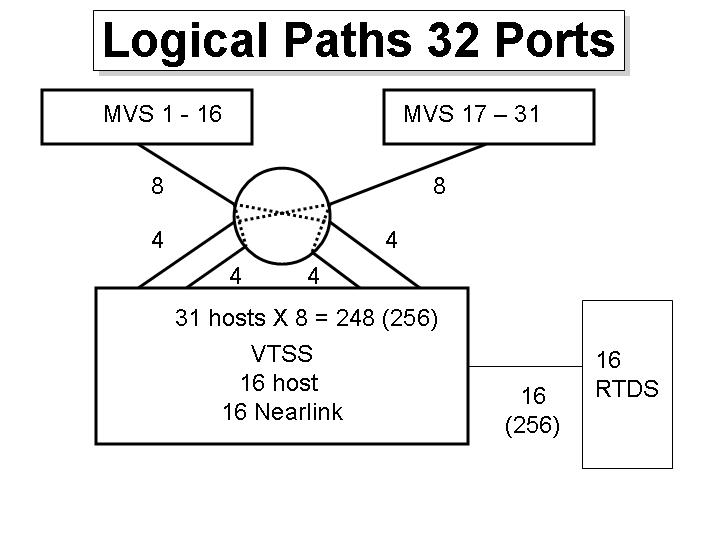
In Figure F-8:
-
The 16 RTDs consume 16 x 16 or 256 logical paths.
-
The maximum logical paths you allocated for a VSM2/3 was 4 to a host requiring maximum throughput (which also satisfied the redundancy/connectivity requirements). Therefore, if you allocated double that number, or 8 logical paths, for each of the 31 hosts in this configuration, you only consume 248, or 8 less than the logical paths remaining for host connections.
Therefore, logical path allocation is not an issue, as it was with VSM2s and VSM3s.