| Oracle® Communications Service Broker Orchestration User's Guide Release 6.1 E29453-01 |
|
|
PDF · Mobi · ePub |
| Oracle® Communications Service Broker Orchestration User's Guide Release 6.1 E29453-01 |
|
|
PDF · Mobi · ePub |
This appendix presents some typical use cases that can be used as examples when creating orchestration logic flows in the Oracle Communications Service Broker Orchestration Studio.
Some of the use cases in this appendix are based on the use cases described in Oracle Communications Service Broker Concepts Guide.
Using the procedures described in the earlier chapters in this guide to create orchestration logic flows, the use cases reproduced here demonstrate how you can build specific flows in the Orchestration Studio.
In addition, each use case displays the XML code that is generated by the Orchestration Studio while you graphically build the flow on the canvas.
The code contains some elements that are automatically inserted by the software and do not affect the behavior of the logic.
The following flows illustrate Service Broker orchestration capabilities.
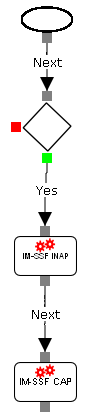
The following use case shows how the Orchestration Engine forwards a session to an online charging application server and then to a VPN service.
To build an IN service interaction flow:
Drag the Conditions icon to canvas and draw a connecting line between Start and the icon.
Drag the IM icon representing IM-SSF INAP to the canvas and then drag the IM icon representing IM-SSF CAP to the canvas.
Draw a connector line from the green connection point on the Conditions icon to IM-SSF INAP and then draw a connector line from IM-SSF INAP to IM-SSF CAP.
Select the Conditions icon and in the Actions tab, click New Group.
Group 0 is displayed under Trigger Point.
Select Group 0, click SIP Method and in the Method field, type INVITE.
Select the IM icon representing IM-SSF INAP and in the Properties tab, type the address of the destination online charging application server in the Alias field and click Apply.
The address of the application server must match the one set for the SCCP Local SSN.
For more information, see the discussion on configuring IM-SSF in Oracle Communications Service Broker Modules Configuration Guide.
Select the IM icon representing IM-SSF CAP and in the Properties tab, type the name of the destination VPN application server in the Alias field and click Apply.
Figure A-1 shows the orchestration logic flow for IN service interaction.
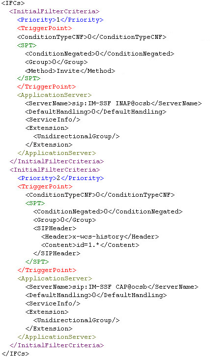
Clicking Source displays the generated XML code of the flow you created graphically.
Figure A-2 shows the source code of the IN service interaction flow.
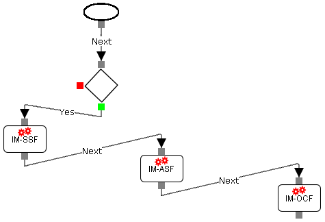
The following use case shows how Service Broker communicates with the IMS network and provides service interaction based on the logic retrieved from the database.
To build an IMS service interaction flow:
Drag the Conditions icon to the canvas and draw a connecting line between Start and the icon.
Drag the IM icons representing the following IMs to the canvas in the order in which they are listed:
IM-SSF
IM-ASF
IM-OCF
Draw a connector line from the green connection point on the Conditions icon to the IM-SSF.
Draw connector lines from the IM-SSF to connect the remaining IM icons in the order you placed them on the canvas.
Select the Conditions icon and in the Actions tab, click New Group.
Group 0 is displayed under Trigger Point.
Select Group 0, click SIP Method and in the Method field, type INVITE.
Select the IM icon representing IM-SSF and in the Properties tab, type the address of the destination online charging application server in the Alias field and click Apply.
The address of the application server must match the one set for the SCCP Local SSN.
For more information, see the discussion on configuring IM-SSF in Oracle Communications Service Broker Modules Configuration Guide.
Select the IM icon representing IM-ASF and in the Properties tab, type the address of the destination SIP application server in the Alias field and click Apply.
Use the format: sip:<ip address>
Select the IM icon representing IM-OCF and in the Properties tab, type the address of the destination charging server in the Alias field and click Apply.
Use the format: sip:<ip address>
Figure A-3 shows the shows the orchestration logic flow for IMS service interaction.
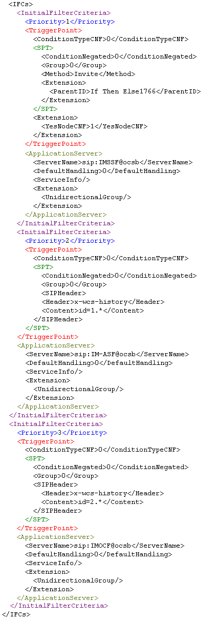
Clicking Source displays the XML code of the flow you created graphically.
Figure A-4 shows the source code of the IMS service interaction flow.
By default, when the OE receives a 302 Moved Temporarily response from an application, the OE releases the session. When you want the OE to continue the session after receiving a 302 Moved Temporarily response, you need to enforce the application that returned the 302 Moved Temporarily response to work as a Back-to-Back (B2B) application.
The following flow demonstrates the case when a VPN service with which the OE communicates through the IM-ASF a 302 Moved Temporarily response. The IM-ASF is set to force the session to continue to the online charging application.
To enforce a B2B flow:
Drag the Conditions icon to canvas and draw a connecting line between Start and the icon.
Drag the IM icon representing the IM-ASF to the canvas and then drag the IM icon representing the IM-OCF to the canvas.
Draw a connector line from the green connection point on the Conditions icon to IM-ASF and and then draw a connector line from IM-ASF to IM-OCF.
Select the Conditions icon and in the Actions tab, click New Group.
Group 0 is displayed under Trigger Point.
Select Group 0, click SIP Method and in the Method field, type INVITE.
Select the IM icon representing IM-ASF and in the Actions tab, do the following:
Select the Back to Back checkbox.
In the Response field, type 302.
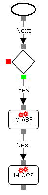
The session is forced to continue to the IM-OCF. Figure A-5 shows a B2B flow.
Clicking Source displays the XML code of the flow you created graphically.
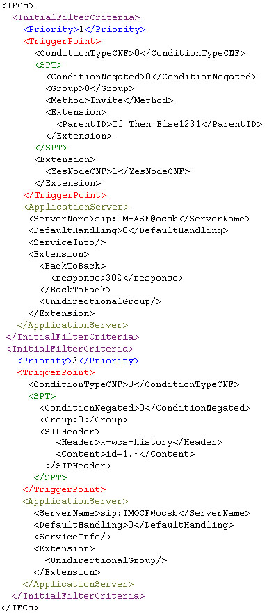
Figure A-6 shows the source code of the B2B flow.
In the following use case, if the session is originating, the OE routes the session to the VPN application server and then to the online charging application server. If the session is terminating, the OE routes the session directly to the online charging application server.
To build a flow that continues the session when conditions are not met:
Drag the Conditions icon to canvas and draw a connecting line between Start and the icon.
Drag the IM icon representing the IM-ASF to the canvas and draw a connecting line from the green connection point on the Conditions icon to the IM icon.
Drag the IM icon representing the IM-OCF to the canvas and draw a connecting line between IM-ASF and IM-OCF.
Drag another IM icon representing the IM-OCF to the canvas and draw a connecting line from the red connection point on the Conditions icon to the IM-OCF you added in step 3.
Select the Conditions icon and in the Actions tab, click New Group.
Group 0 is displayed under Trigger Point.
Select Group 0 and click SIP Header.
In the right pane, type the following:
Header field: x-wcs-session-case
Content field: x-wcs-session-case:orig
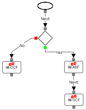
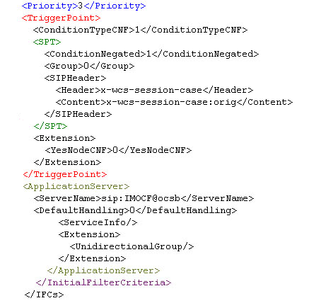
Figure A-7 shows the conditional flow. If the message header meets the conditions, it goes to the IM-ASF and then to IM-OCF. If the message header does not meet the conditions, it goes directly to IM-OCF.
Clicking Source displays the XML code of the flow you created graphically.
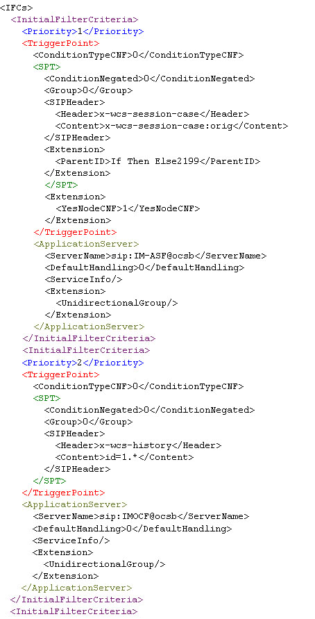
Figure A-8 and Figure A-9 show the source code of the conditional flow.
When you create an orchestration logic using the Orchestration Studio, Service Broker stores the orchestration logic in SM-LSS as a part of the subscriber's profile. With Online Mediation Controller, subscriber profile data, including subscriber-specific orchestration logic, is stored in the Subscriber Store instead of SM-LSS.
To access the Subscriber Store, Service Broker uses the Subscriber Provisioning API. The API provides operations for adding and managing subscriber profile data in the store. The operation that adds a new subscriber to the Subscriber Store is called storeSubscriber. In the request body, you provide the orchestration logic in the iFC format.
To facilitate the process of creating of iFC, you can build the orchestration logic using the Orchestration Studio visual tools. Because the Orchestration Studio generates the iFC code of the orchestration logic, you can copy the iFC representation and paste it into the storeSubscriber request body.
To create an orchestration logic for a subscriber in Online Mediation Controller:
Create a subscriber profile in SM-LSS. For more information, see the discussion on configuring SM-LSS in Oracle Communications Service Broker Modules Configuration Guide.
Build an orchestration flow for the subscriber using the Orchestration Studio tools. See "Building an Orchestration Logic Flow" for more information.
To view the iFC code that the Orchestration Studio generated for the orchestration flow, click Source.
Copy the entire iFC code and paste it into the <ifc> element of the storeSubscriber request body.
For more information, see the discussion on the subscriber store API reference in Oracle Communications Service Broker Subscriber Store User's Guide.
|
Copyright © 2010, 2013, Oracle and/or its affiliates. All rights reserved. Legal Notices |
|