| StorageTek Virtual Library Extension Planning Guide E41530-04 |
|


 Previous |
 Next |
This appendix contains the following configuration examples (all examples are direct connect, no switch):
"VLE Configuration Examples" shows the VLE GUI screens used for these examples.
The following sections describe the VLE GUI configuration screens used to configure the examples in this appendix. For more information on the VLE GUI, see VLE Installation, Configuration, and Service Guide.
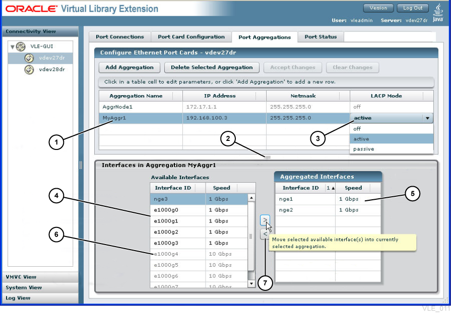
Figure A-1 shows the Port Card Configuration tab, which is used in all examples. Assume the default Netmask value and use whatever value you want for the Port's Host Name field. The table for each example provides the IP Address and Check Box (Replication, UUI, Remote) values that correspond to the Interface ID field value.
In Figure A-1:
1 - Currently selected aggregation.
2 - Drag up or down to resize panes.
3 - Drop down selection list of options.
4 - Pool of port interfaces available for aggregations
5 - Interfaces in currently selected aggregation.
6 - Ports greyed out if wrong speed for aggregation.
7 - Move interfaces into and out of aggregations with arrow buttons.
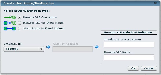
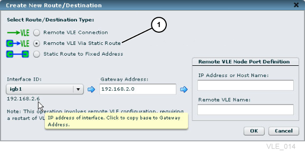
Figure A-2 and Figure A-3. You use one of these dialog boxes in "Example 3: VLE to VLE Copy".
1 - Selection modifies available entry fields
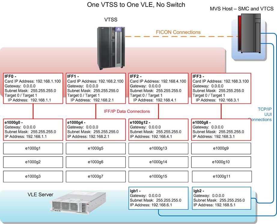
As Figure A-4 and Table A-1 show, in this one VTSS to one VLE example, two targets on each IFF card connect to a single port on the VLE, where the IP addresses must match. Note that the third octet of the IP addresses is unique to each IFF card to VLE port connection, so these connections share a unique subnet.
Using two targets on each IFF card optimizes performance, because each target represents a socket, which enables a migrate and a recall to occur simultaneously on the same IFF card. Two targets optimizes performance, there is no performance benefit to assigning more than two targets per IFF card to the same VLE port.
Table A-1 Example 1 Configuration Values
|
IFF Card and Target |
IPIF Value |
Interface ID |
IP Address |
Check Box |
|
Data Connections |
||||
|
IFF0 Target 0 |
0A:0 |
igb4 |
192.168.1.1 |
Replication |
|
IFF0 Target 1 |
0A:1 |
|||
|
IFF1 Target 0 |
0I:0 |
igb8 |
192.168.2.1 |
|
|
IFF1 Target 1 |
0I:1 |
|||
|
IFF2 Target 0 |
1A:0 |
igb16 |
192.168.4.1 |
|
|
IFF2 Target 1 |
1A:1 |
|||
|
IFF3 Target 0 |
1I:0 |
igb12 |
192.168.3.1 |
|
|
IFF3 Target 1 |
1I:1 |
|||
|
UUI Connections |
||||
|
igb1 |
192.168.6.1 |
UUI |
||
|
igb2 |
192.168.5.1 |
|||
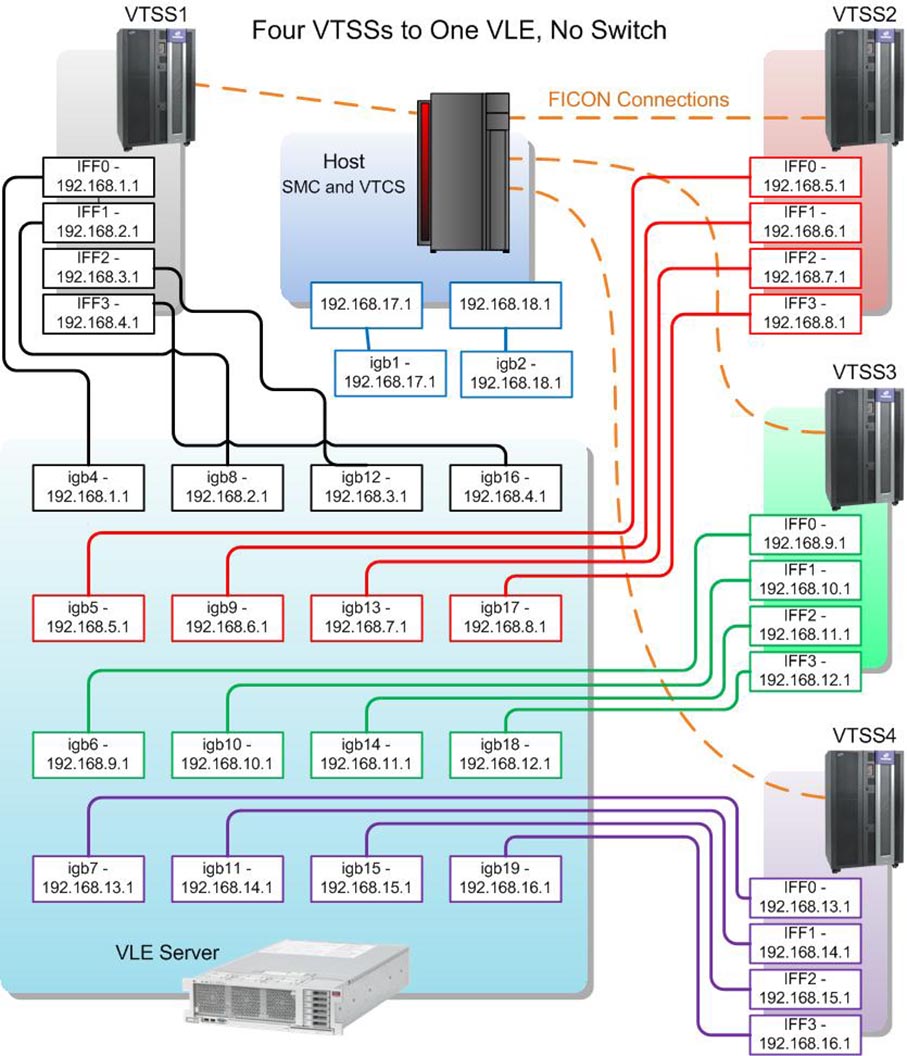
As Figure A-5 and Table A-2 show, in this four VTSS to one VLE example, each IFF target to VLE port connection (where the IP addresses must match) is on its own unique subnet, as shown by the different colors for each subnet (UUI connections are shown in blue).
Table A-2 Example 2 Configuration Values
|
VSM5 |
IFF Card and Target |
IPIF Value |
Interface ID |
IP Address |
Check Box |
|
Data Connections |
|||||
|
VTSS1 |
IFF0 Target 0 |
0A:0 |
igb4 |
192.168.1.1 |
Replication |
|
IFF1 Target 0 |
0I:0 |
igb8 |
192.168.2.1 |
||
|
IFF2 Target 0 |
1A:0 |
igb12 |
192.168.3.1 |
||
|
IFF3 Target 0 |
1I:0 |
igb16 |
192.168.4.1 |
||
|
VTSS2 |
IFF0 Target 0 |
0A:0 |
igb5 |
192.168.5.1 |
|
|
IFF1 Target 0 |
0I:0 |
igb9 |
192.168.6.1 |
||
|
IFF2 Target 0 |
1A:0 |
igb13 |
192.168.7.1 |
||
|
IFF3 Target 0 |
1I:0 |
igb17 |
192.168.8.1 |
||
|
VTSS3 |
IFF0 Target 0 |
0A:0 |
igb6 |
192.168.9.1 |
|
|
IFF1 Target 0 |
0I:0 |
igb10 |
192.168.10.1 |
||
|
IFF2 Target 0 |
1A:0 |
igb14 |
192.168.11.1 |
||
|
IFF3 Target 0 |
1I:0 |
igb18 |
192.168.12.1 |
||
|
VTSS4 |
IFF0 Target 0 |
0A:0 |
igb7 |
192.168.13.1 |
|
|
IFF1 Target 0 |
0I:0 |
igb11 |
192.168.14.1 |
||
|
IFF2 Target 0 |
1A:0 |
igb15 |
192.168.15.1 |
||
|
IFF3 Target 0 |
1I:0 |
igb19 |
192.168.16.1 |
||
|
UUI Connections |
|||||
|
igb1 |
192.168.17.1 |
UUI |
|||
|
igb2 |
192.168.18.1 |
||||
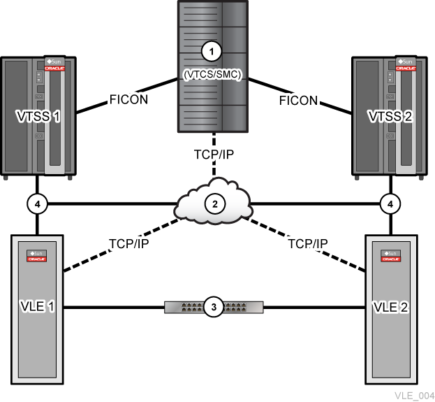
As Figure A-6 and the example values in Table A-3 show, in this two VTSSs to two VLEs, VLE to VLE copy example:
Each VTSS is connected to the MVS Host (1) and is cross-connected to each VLE for VTSS to VLE copy (4 are the VTSS to VLE TCP/IP connections and 2 is the 1GigE TCP/IP network).
The VLEs are connected to each other through a network that includes the 10 GigE switch (3).
Each VTSS, therefore, can migrate a separate VTV copy to each VLE, which provides a redundancy/high availability solution similar to that provided by Clustered VTSS. The default behavior can be that the second copy is made through VLE to VLE connections. To enforce VTSS to VLE migration for the second copy, use the STORCLAS FROMLST parameter. For more information, see Configuring the Host Software for VLE.
Table A-3 Example 3 Configuration Values
|
VSM5 |
IFF Card and Target |
IPIF Value |
VLE, Interface ID |
IP Address |
Check Box |
|
VLE to VTSS Data Connections |
Replication |
||||
|
VTSS1 |
IFF0 Target 0 |
0A:0 |
VLE1, igb4 |
192.168.1.1 |
|
|
IFF1 Target 0 |
0I:0 |
VLE1, igb8 |
192.168.2.1 |
||
|
IFF2 Target 0 |
1A:0 |
VLE1, igb12 |
192.168.3.1 |
||
|
IFF3 Target 0 |
1I:0 |
VLE1, igb16 |
192.168.4.1 |
||
|
IFF0 Target 1 |
0A:1 |
VLE2, igb4 |
192.168.5.1 |
||
|
IFF1 Target 1 |
0I:1 |
VLE2, igb8 |
192.168.6.1 |
||
|
IFF2 Target 1 |
1A:1 |
VLE2, igb12 |
192.168.7.1 |
||
|
IFF3 Target 1 |
1I:1 |
VLE2, igb16 |
192.168.8.1 |
||
|
VSM5 |
IFF Card and Target |
IPIF Value |
VLE, Interface ID |
IP Address |
Check Box |
|
VLE to VTSS Data Connections |
|||||
|
VTSS2 |
IFF0 Target 0 |
0A:0 |
VLE1, igb5 |
192.168.9.1 |
Replication |
|
IFF1 Target 0 |
0I:0 |
VLE1, igb9 |
192.168.10.1 |
||
|
IFF2 Target 0 |
1A:0 |
VLE1, igb13 |
192.168.11.1 |
||
|
IFF3 Target 0 |
1I:0 |
VLE1, igb17 |
192.168.12.1 |
||
|
IFF0 Target 1 |
0A:1 |
VLE2, igb5 |
192.168.13.1 |
||
|
IFF1 Target 1 |
0I:1 |
VLE2, igb9 |
192.168.14.1 |
||
|
IFF2 Target 1 |
1A:1 |
VLE2, igb13 |
192.168.15.1 |
||
|
IFF3 Target 1 |
1I:1 |
VLE2, igb17 |
192.168.16.1 |
||
|
VLE to VLE Data Connections |
|||||
|
VLE1, ixgbe1 |
192.168.17.1 |
Remote |
|||
|
VLE1, ixgbe3 |
192.168.18.1 |
||||
|
VLE2, ixgbe1 |
192.168.17.2 |
||||
|
VLE2, ixgbe3 |
192.168.18.2 |
||||
|
UUI Connections |
|||||
|
VLE1, igb1 |
192.168.19.1 |
UUI |
|||
|
VLE1, igb2 |
192.168.20.1 |
||||
|
VLE2, igb1 |
192.168.21.1 |
||||
|
VLE2, igb2 |
192.168.22.1 |
||||
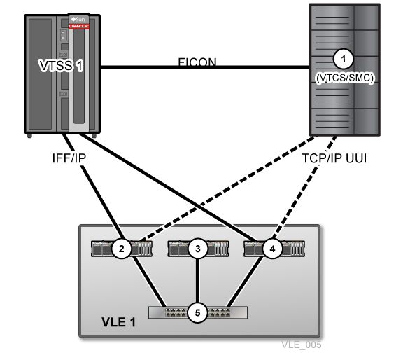
As the example values in Table A-4 show, in this one VTSS to a 3-Node VLE example:
The 10 GigE switch (5) provides an internal network for data exchange between the nodes that make up VLE1 where 2 - Node 1, 3 - Node 2, and 4 - Node 3.
To provide redundancy, nodes 1 and 3 both have IFF/IP connections for data exchange with the VTSS and TCP/IP UUI connections to the Mainframe host.
Node 3 is a data repository and has no Mainframe host (1) or VTSS connections.
Table A-4 Example 4 Configuration Values
|
IFF Card and Target |
IPIF Value |
VLE Node, Interface ID |
IP Address |
Check Box |
|
Data Connections |
Replication |
|||
|
IFF0 Target 0 |
0A:0 |
Node 1, igb4 |
192.168.1.1 |
|
|
IFF0 Target 1 |
0A:1 |
|||
|
IFF1 Target 0 |
0I:0 |
Node 1, igb8 |
192.168.2.1 |
|
|
IFF1 Target 1 |
0I:1 |
|||
|
IFF2 Target 0 |
1A:0 |
Node 3, igb4 |
192.168.3.1 |
|
|
IFF2 Target 1 |
1A:1 |
|||
|
IFF3 Target 0 |
1I:0 |
Node 3, igb8 |
192.168.4.1 |
|
|
IFF3 Target 1 |
1I:1 |
|||
|
UUI Connections |
||||
|
Node 1, igb1 |
192.168.5.1 |
UUI |
||
|
Node 3, igb2 |
192.168.6.1 |
|||
|
 Copyright © 2013, 2014, Oracle and/or its affiliates. All rights reserved. Legal Notices |
|