| StorageTek Virtual Library Extension Planning Guide E41530-04 |
|


 Previous |
 Next |
This appendix contains the following link aggregation examples:
"VLE GUI Configuration Screens" shows the VLE GUI screens used for these examples.
The following section shows the VLE GUI Configuration Screen used to configure the examples in this appendix. For more information on the VLE GUI, see VLE Installation, Configuration, and Service Guide.
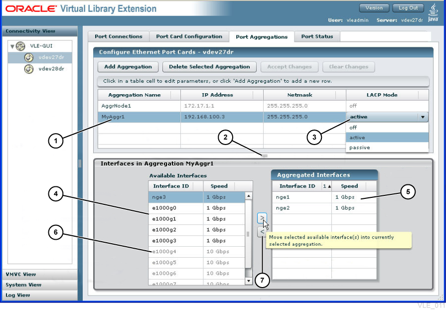
Figure B-1 shows the Port Aggregations tab, which is used in all examples.
1 - Currently selected aggregation.
2 - Drag up or down to resize panes.
3 - Drop down selection list of options.
4 - Pool of port interfaces available for aggregations
5 - Interfaces in currently selected aggregation.
6 - Ports greyed out if wrong speed for aggregation.
7 - Move interfaces into and out of aggregations with arrow buttons.
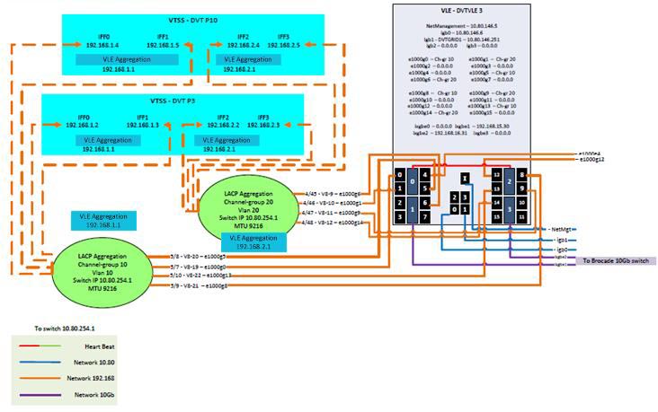
Figure B-2 shows a single-node VLE connected to two VSM5s as follows:
Ports igb4, igb9, igb12, and g1000g13 are aggregated to the switch's Channel group 10 with an IP address of 192.168.1.1 and the aggregation is connected each VSM5's IFF0 and IFF1 cards.
Ports igb4, igb8, igb13, and igb18 are aggregated to the switch's Channel group 20 with an IP address of 192.168.2.1 and the aggregation is connected each VSM5's IFF2 and IFF3 cards.
Note the following benefits versus a non-aggregated configuration:
Simplify the configuration: Just two IP addresses were required at the VLE (192.168.1.1 and 192.168.2.1).
Provide fault tolerance: The links to each aggregation are configured evenly and horizontally across the VLE to prevent an outage to a aggregation if a network adapter fails. Additionally, both aggregations serve each VSM5, so if an aggregation fails, the other aggregation can continue the connection to the VSM5.
Load balancing and bandwidth optimization: Each aggregation consists of four separate links to distribute the traffic load and optimize bandwidth.
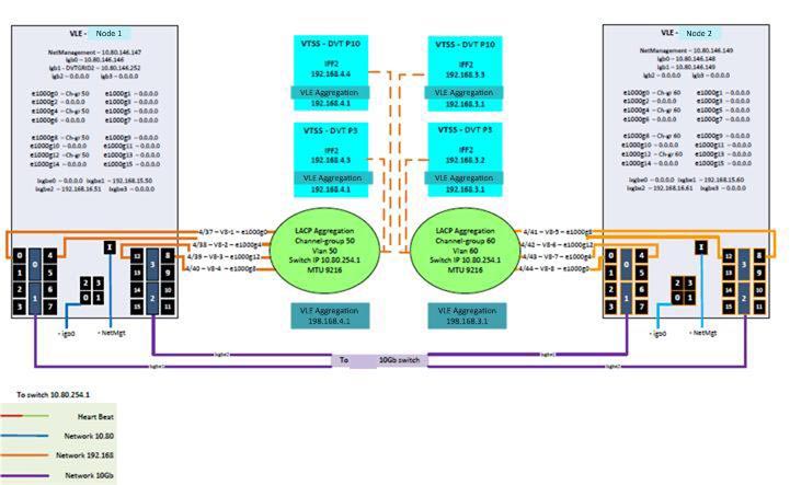
Figure B-3 shows a two-node VLE connected to two VSM5s as follows:
Ports igb4, igb8, igb12, and g1000g12 of Node 1 are aggregated to the switch's Channel group 50 with an IP address of 192.168.4.1 and the aggregation is connected each VSM5.
Ports igb4, igb8, igb12, and g1000g12 of Node 2 are aggregated to the switch's Channel group 60 with an IP address of 192.168.3.1 and the aggregation is connected each VSM5.
Note the following benefits versus a non-aggregated configuration:
Simplify the configuration: Just two IP addresses were required at the VLE (192.168.4.1 and 192.168.3.1).
Provide fault tolerance: The links to each aggregation are configured evenly and horizontally across each node to prevent an outage to a aggregation if a network adapter fails. Additionally, both aggregations serve each VSM5, so if an aggregation fails, the other aggregation can continue the connection to the VSM5. Finally, each node services each VSM5, providing additional redundancy.
Load balancing and bandwidth optimization: Each aggregation consists of four separate links to distribute the traffic load and optimize bandwidth.
|
 Copyright © 2013, 2014, Oracle and/or its affiliates. All rights reserved. Legal Notices |
|