- 4.3.1 Move Oracle Virtual Compute Appliance
- 4.3.2 Stabilize Oracle Virtual Compute Appliance
- 4.3.3 Stabilize Oracle Virtual Compute Appliance Using Leveling Feet
- 4.3.4 Stabilize Oracle Virtual Compute Appliance Using Mounting Brackets
- 4.3.5 Attach a Ground Cable (Optional)
- 4.3.6 Remove the F1-15 Director Switch Bracket
This section describes each phase of the hardware installation procedure for the Oracle Virtual Compute Appliance.
The following procedure describes how to move the Oracle Virtual Compute Appliance:
Ensure that the rack doors are closed and secured.
Ensure that the leveling and stabilizing feet on the rack are raised and out of the way.
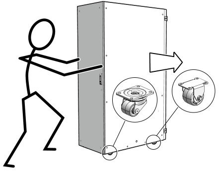
Push the system from the back of the rack to the installation site.
CautionNever attempt to move an Oracle Virtual Compute Appliance by pushing on the rack side panels. Pushing on the rack side panels can tip over the rack. This action can cause serious personal injury or death as well as damage to the equipment.
When moving your Oracle Virtual Compute Appliance to the installation site, the front casters do not pivot; you must steer the unit by moving the rear casters. You can safely maneuver the system by carefully pushing it. See Figure 4.2.
It is preferred to use three people to move the rack: one person in front and two persons in back to help guide the rack. When transporting configured racks from one location to another, take care to move them slowly, 0.65 meters per second (2.13 feet per second) or slower.
Carefully examine the transportation path. Avoid obstacles such as doorways or elevator thresholds that can cause abrupt stops or shocks. Go around obstacles by using ramps or lifts to enable smooth transport.
CautionNever tip or rock the Oracle Virtual Compute Appliance because the rack can fall over.
When the rack is at the installation site, verify that no components or connections have become dislodged or disconnected during transport. If necessary, re-attach components and cables properly.
After moving Oracle Virtual Compute Appliance to the installation site, stabilize the rack to ensure that it does not move or tip over. You can stabilize the rack permanently by extending the rack leveling feet, using mounting brackets, or both. After installation, use the leveling feet and the brackets to stabilize the system.
The rack contains four leveling feet that can be lowered to stabilize the rack. The leveling feet can be used even when the rack is permanently secured to the floor. To adjust the leveling feet, do the following:
Locate the four leveling feet at the bottom four corners of the rack. See Figure 4.3.
Table 4.2 Figure Legend
Item
Description
1
Distance from the edge of the mounting feet to the side of the rack is 33.75 mm (1.33 inches)
2
Width from the outside edges of the leveling feet is 532.5 mm (20.96 inches)
3
Width from the inside edges of the leveling feet is 429 mm (16.89 inches)
4
Distance from the edge of the feet to the front rack surface is 73.75 mm (2.90 inches)
5
Depth of the outside edges of the leveling feet is 1058.5 mm (41.67 inches)
6
Distance from the edge of the leveling feet to the rear rack surface is 32.5 mm (1.28 inches)
7
Distance from the center of front casters to the side of the rack is 86.7 mm (3.41 inches)
8
Width between the center of the front casters is 426.6 mm (16.80 inches)
9
Distance from the center of the rear casters to the rear of the rack is 173.7 mm (6.83 inches)
10
Depth between the front and rear casters is 828.6 mm (32.62 inches)
11
Distance between the rear casters and the rear of the rack is 162.4 mm (6.39 inches)
12
Distance from the center of rear casters to the side of the rack is 96.4 mm (3.80 inches)
13
Width between the center of the rear casters is 407.2 mm (16.03 inches)
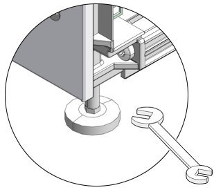
Using the SW 12-mm wrench, lower the leveling feet to the floor. See Figure 4.4.
When lowered correctly, the four leveling feet should support the full weight of the Oracle Virtual Compute Appliance.
The rack can be permanently mounted to the installation site floor using the same four mounting brackets that secured the rack to the shipping pallet. Use the front and rear brackets to stabilize the rack to the installation floor. Prepare the installation site by drilling four holes into the floor. Before permanently stabilizing the Oracle Virtual Compute Appliance rack using the mounting brackets, drill the mounting holes.
Obtain four bolts and washers to mount the system to the floor.
The bolt holes in the mounting bracket have a 10-mm diameter.
Oracle does not provide mounting bolts because different floors require different bolt types and strengths.
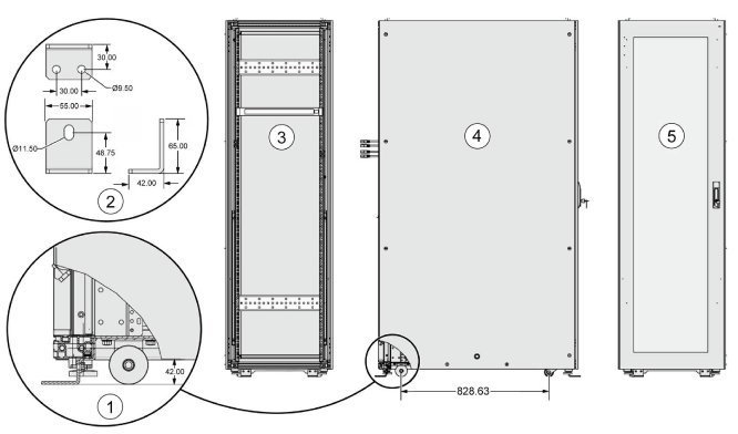
See Figure 4.5 to find the location and dimensions of the mounting brackets.
Table 4.3 Figure Legend
Item
Description
1
Mounting bracket location
2
Mounting bracket dimensions
3
Rack rear
4
Rack side
5
Rack front
Position the Oracle Virtual Compute Appliance rack over the drilled holes.
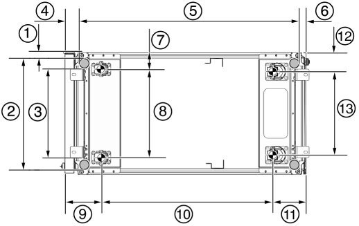
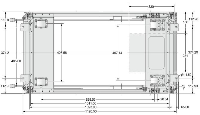
Figure 4.6 shows the bottom view of the system, and the location for the mounting hole and floor cutout dimensions.
Figure 4.6 Bottom View of Oracle Virtual Compute Appliance Rack Showing Mounting Hole and Floor Cutout Dimensions
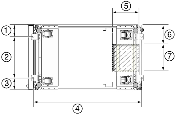
Table 4.4 Figure Legend
Item
Description
1
Distance from mounting bracket to the edge of the rack is 113 mm (4.45 inches)
2
Width between the centers of the mounting hole slots is 374 mm (14.72 inches)
3
Distance between mounting bracket to the edge of the rack is 113 mm (4.45 inches)
4
Distance between the centers of the front and rear mounting hole slots is 1120 mm (44.1 inches)
5
Depth of cable-routing floor cutout is 330 mm (13 inches)
6
Distance between the floor cutout and the edge of the rack is 160 mm (6.3 inches)
7
Width of cable-routing floor cutout is 280 mm (11 inches)
(Optional) If you plan to route data or power distribution unit (PDU) power cords down through the bottom of the rack, you will need to cut a hole in the installation site floor. Cut a rectangular hole below the rear portion of the rack, between the two rear casters and behind the RETMA (Radio Electronics Television Manufacturers Association) rails.
Figure 4.7 shows the base positions of the rack from the bottom.
CautionDo not create a hole where the rack casters or leveling feet brackets will be placed.
Open the front and rear Oracle Virtual Compute Appliance rack doors.
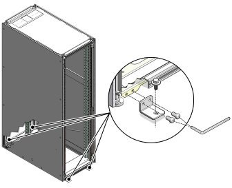
Using a 6-mm hexagon Allen wrench key, install the mounting brackets to the rack. See Figure 4.8.
Using bolts and washers that are appropriate for your installation site, permanently mount your system to the floor using the four mounting brackets. See Figure 4.8.
NoteThe bolts that are required for securing the Oracle Virtual Compute Appliance rack to the floor vary depending on the installation location. Select bolts that are appropriate for your location.
Firmly tighten all of the bolts that secure the mounting brackets to the Oracle Virtual Compute Appliance rack side doors and to the floor.
Oracle Virtual Compute Appliance power distribution units (PDUs) achieve earth ground through their power cords. Final chassis ground is achieved by way of the ground prong when you connect the power cord to a socket. For additional grounding, attach a chassis earth ground cable to the system. The additional ground point enables electrical current leakage to dissipate more efficiently.
The PDU power input lead cords and the ground cable must reference a common earth ground. If they do not, then a difference in ground potential can be introduced. If you are unsure of your facility's PDU receptacle grounding, then do not install a ground cable until you confirm that there is a proper PDU receptacle grounding. If a difference in ground potential is apparent, then you must take corrective action.
A grounding cable is not shipped with the Oracle Virtual Compute Appliance.
Ensure that the installation site has properly grounded the power source in the data center. The facility PDU must have earth ground.
Ensure that all grounding points, such as raised floors and power receptacles, reference the facility ground.
During manufacturing, the ground cable attachment area might be a painted or coated surface. Ensure that direct, metal-to-metal contact is made for this installation.
Attach the ground cable to one of the attachment points located at the bottom rear of the system frame. See Figure 4.9.
The attachment point is an adjustable bolt that is inside the rear of the system cabinet on the right side.
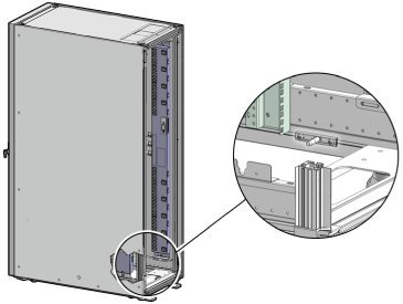
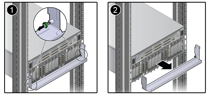
Each F1-15 Director Switch is shipped with a bracket that secures the IO modules in their installed position. This shipping bracket is removed after the Oracle Virtual Compute Appliance is installed and stabilized in its allocated space.
Locate the shipping bracket at the rear of the Oracle Fabric Interconnect F1-15 Director Switch.
Pull the tabs on the left and right hand side towards the center to unlock the bracket.
Carefully pull the bracket away from the F1-15 Director Switch and out of the rack.
Repeat these steps to remove the shipping bracket on the second F1-15 Director Switch.