How VRRP Works
Note the following VRRP router terms:
-
Router name – A system-wide unique identifier.
-
Virtual Router ID (VRID) – A unique number used to identify a virtual router on a given network segment. VRIDs identify the virtual router within a LAN.
-
Primary IP address – The source IP address of the VRRP advertisement.
-
Virtual IP addresses (VRIP) – An IP address associated with a VRID from which other systems can obtain network service. The VRIP is managed by the VRRP instances belonging to a VRID.
-
Master router – A VRRP instance that performs the routing function for the virtual router at a given time. Only one master router is active at a time for a given VRID. The master router controls the IPv4 or IPv6 address or addresses that are associated with the virtual router. The virtual router forwards the packets that are sent to the IP address of the master router.
-
Backup router – A VRRP instance for a VRID that is active but not in the master state is called a backup router. Any number of backup routers can exist for a VRID. A backup router assumes the role of a master router if the current master router fails.
-
VRRP parameters – Includes priority, advertise interval, pre-empt mode, and accept mode.
-
VRRP state information and statistics.
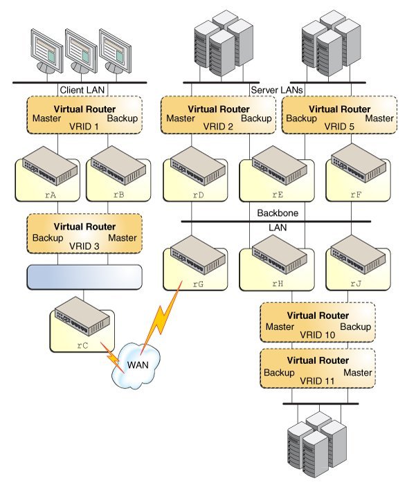
The following VRRP load-sharing configuration figure shows that the multiple VRIDs can exist on a single router interface. The accompanying text explains the VRRP components that are used in the figure. This VRRP load-sharing configuration illustrates that multiple VRIDs can exist on a single router interface.
Figure 1 Load-Sharing Configuration of VRRP in a LAN

-
Router rA is the master router for virtual router VRID 1 and the backup router for VRID 3. Router rA handles the routing of packets that are addressed to the virtual IP (VIP) address for VRID 1 and is ready to assume the routing role for VRID 3.
-
Router rB is the master router for virtual router VRID 3 and the backup router for VRID 1. Router rB handles the routing of packets that are addressed to the VIP for VRID 3 and is ready to assume the routing role for VRID 1.
-
Router rC does not have VRRP functions, but it uses the VIP for VRID 3 to reach the client LAN subnet.
-
Router rD is the master router for VRID 2. Router rF is the master router for VRID 5. Router rE is the backup router for both of these VRIDs. If rD or rF fails, rE becomes the master router for that VRID. Both rD and rF could fail at the same time. A VRRP router can be the master router for one or more VRIDs.
-
Router rG is the wide area network (WAN) gateway for the backbone LAN. All of the routers attached to the backbone are sharing routing information with the routers on the WAN by using a dynamic routing protocol such as OSPF. VRRP is not involved in this aspect, although router rC advertises that the path to the client LAN subnet is through the VIP of VRID 3.
-
Router rH is the master router for VRID 10 and the backup router for VRID 11. Likewise, router rJ is the master router for VRID 11 and the backup router for VRID 10.