11 Installing Media Engine Clusters
This chapter provides information on how to install a Media Engine (ME) cluster, a group of ME systems that operate together to support redundancy and failover, high-availability, load balancing, and configuration.
Media Engine Cluster Overview
A ”high-availability” cluster is a group of ME systems that provides a single point of configuration management, and at the same time, expands functionality across multiple devices participating in the cluster. An ME master manages the configuration for the entire cluster. All members of the cluster share network resources, network load, media ports and streaming, registration, and other processes.
ME systems within a cluster may be geographically dispersed in the network. A cluster recovers from the failure of one or more cluster members through health monitoring, shared master services migration, and network redundancy using the Virtual Router Redundancy Protocol (VRRP).
A cluster can be set up to operate as a two-system primary/standby redundant configuration.
Cluster Operations and Services
In the two-system redundant configuration, one ME system is the active master, performing signaling & media processing, and the other ME system is available as a standby system for the signaling & media processing if the master fails. Master failover allows another ME system to assume the master role in the cluster should the originally configured master become unavailable. VRRP is responsible for handling the failover from the master to the backup device.
Master-Services
The master-services configuration is responsible for mirroring the state of the cluster to allow reliable failover to a standby device.
Note:
You must have the master-services > events object enabled for clustering to work.The following sections describe the suggested settings for the master-services objects:
Cluster-Master
A cluster-master configuration on the ME system designated as the master is responsible for passing configuration changes to cluster members. A secondary property called takeover-timer-value specifies the number of milliseconds (such as 500) that the master-service stays in ”awaiting takeover” mode at boot time.
Use the show cluster-master -v command to display the current takeover-timer value. When the ME boots, each hosted master-service waits for this period to determine if any existing devices in the cluster are already running that service before assuming mastership.
Accounting
When enabled, accounting services supports RADIUS accounting, system logging (syslog), DIAMETER protocol services, the accounting database, and the accounting file-system.
Database
The master-services database object allows you to configure maintenance and other settings for the ME system database. The ME database is the local repository for call accounting records and media files.
The database master service should be on a backup ME system, with the secondary property preempt set to true. This will help maintain the data in one location in the event of a brief service outage.
The preempt property specifies whether the master-service should resume the mastership if it has gone down and then returned to operation. If set to true, the master resumes its position. If set to false, the backup service retains master control.
Server-Load
The master-services server-load object configures the ME to calculate server load. This object must be enabled if your dial plan arbiter rule settings use least-load as the routing algorithm option. (The arbiter rule property sets the criteria by which the ME selects the server to which it forwards calls.)
Configure the server-load master-service for outbound server load balancing or server based admission\emission control. Currently, the server-load master-service should be linked to the VRRP SIP signaling interfaces over a configured group.
Call-Failover
The call-failover master-service configures failover for the media and signaling streams. As a master-service, the configured host ME master distributes copies of the media and kernel rules to all backup devices in a cluster. The ME uses the database on the host box, but enabling call-failover ensures that there is an active copy of the database on another device in the cluster in the event of a failure.
Load-Balancing
The master-services load-balancing object configures ME systems to host the load-balancing master service. For detailed information, see Configuring Cluster Load Balancing.
File-Mirror
The master-services file-mirror object sets all participating ME systems to share particular files (the types of files shared are preset in the ME operating system), such as media recordings, log files, etc. The file-mirror master service distributes files to all ME systems listed as hosts for the service.
Once the files are mirrored, you can play them back from any ME system that functions as a host.
Sampling
The master-services sampling object opens the mechanism for setting the interval at which the ME samples operational aspects of the system for either:
-
Display in the ME Management System, or
-
For sending to a server
By setting sampling for a status provider, you can view data for that provider over a specified period of time. The ME supports two sampling targets: a Postgres SQL database and an IBM tivoli server. (Set the provider data sent to the target using the status and provider objects. See Oracle Communications WebRTC Session Controller Media Engine Object Reference for more information on configuring these objects.)
Once you have enabled sampling, the master service stores the samples in its local database.
Heartbeat Interface, BOOTP, and Messaging
Use the Ethernet physical interface eth0 as the heartbeat interface for the ME cluster. This interface is used by default for any backup ME system that you added to the cluster. The systems will perform a BOOTP request over that interface and you will be able to add these systems by creating an entry for each to the configuration, and then booting them.
Once an ME is a member of the cluster, that system will receive a saved configuration file (cxc.cfg) from the master. Each time the cxc.cfg file is saved on the master, the latest copy of the cxc.cfg file is sent to each device in the cluster. You will need to configure a messaging interface on each cluster member so that the master knows the interface over which members of the cluster will receive the cxc.cfg file.
Event Logging
Event logs are stored on each box individually and represent the events that occurred on that particular ME system. You configure event logging in the services/event-logs configuration object. The recommended event log filters on a cluster are as follows:
-
Local-database all error
-
File name system error
-
File name krnlsys info
-
File name system info
-
File name db info
Network Time Protocol (NTP)
Ensure that you have NTP configured on all ME systems, ensuring that they point to a timeserver which will keep their time synchronized.
WARNING:
DO NOT use a VRRP interface as your route to the timeserver, since one device will always have the VRRP interfaces down and will not be able to contact the NTP server.
If you do not have access to an external NTP server, configure one of the clustered ME systems to be an NTP server for the other cluster members. It is important to run NTP, as the time on all clustered system must be kept synchronized. If the times on the ME systems drift apart, the Denial of Service (DOS) software will not function properly, as timestamps are required to make this work across the cluster.
You can configure the NTP-server on the messaging interface on one ME system, and have all other devices point to this IP address in their NTP-client configuration.
Cluster Redundancy Operations
The ME cluster redundancy operates as follows:
-
Internal messaging is exchanged so that each ME system knows the state of the other boxes, either up or down.
-
If the active cluster master goes down, the box listed next in the list of cluster masters becomes the active cluster master. (Note that control does not automatically go back to the original system when it returns to service.)
-
All the other master services work similarly, with an ordered list of devices that can run the service and the active service running on the next device in the list if the active master fails.
If an ME system fails, another device in the cluster will assume its network interfaces using VRRP.
Notes on Cluster Management
The ME cluster management operates as follows:
-
Within a given cluster, one box functions as the active cluster master.
-
Configuration and management of all boxes within a cluster is performed through the cluster master.
-
There are no limitations on how many boxes within the cluster can be configured as backup cluster masters or backups for any of the master services.
-
The configuration contains a list of boxes that can be cluster masters. The ordering of this list reflects the order in which boxes attempt to become master (for example, the box listed first becomes the initial master, if that box fails then the next box in the list attempts to become the master.)
-
The ME Management System connects to the cluster master and provides a single point of management for the following:
-
Configuration
-
Status reports
-
Call logs
-
Accounting data
-
Actions
-
-
The CLI provides single point of management for configuration using the CLI on the cluster master. The CLI is still available on all the other devices in the cluster, so any CLI commands can be executed on individual boxes.
-
Note that the management functionality available from a given cluster is dependent on the functionality being performed by that cluster. For example, call logs are available only on clusters where signaling is performed; media recordings are available only on clusters where media streaming is performed.
Cluster Installation Prerequisites
Before beginning the cluster installation, ensure that any L2/L3 switch supporting the cluster has the Port Fast, Fast Link, or similar feature turned on. This allows the switch to run the Spanning Tree 802.1 protocol so that the switch ports being used by the ME go directly to the ”forwarding” state. If the switch does not support Port Fast or Fast Link, disable the Spanning Tree protocol for the VLANs associated with the switch ports being used by the ME.
Cluster Installation Procedure
There are a number of steps that you need to follow to install an ME network cluster. You will need to know certain information about all the systems in the cluster for proper operation.
Each step uses a sample CLI session of commands that best illustrate how to best configure important settings.
-
Determine the specific ME system to assume the role of cluster master. Configure master-services to specify the device the cluster to assume initial mastership.
NNOS-E> config master-services
config master-services> config cluster-master
config cluster-master> set admin enabled
config cluster-master> set host-box cluster\box 1
config cluster-master> set host-box cluster\box 2
config cluster-master> set group 1
config cluster-master> return
-
Note the MAC address (identifier) on each device in the cluster. The MAC address is on a sticker on the back of the system. Make a note of each MAC address.
On each device, if there is no sticker present, attach a laptop or standard PC to the system console port and perform the following steps:
-
Power up the system
-
At the NNME prompt, execute the show interface-details eth0 command to display the MAC address.
-
-
Attach a console to the cluster master and power up the ME system.
-
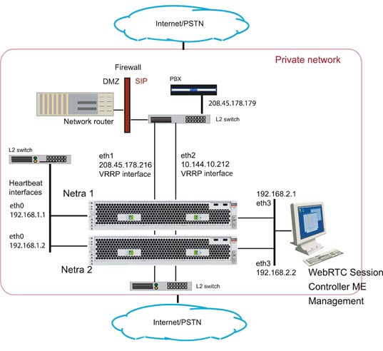
Configure the cluster master by configuring the Ethernet interfaces, IP addresses, and protocols. Ethernet interface eth0 is the ”heartbeat” interface for the cluster. Use the eth0 interface on each ME system as the connection to the cluster.
NNOS-E> config cluster
config cluster> config box 1
config box 1> set identifier 00:04:23:d7:9f:34
config box 1> config interface eth0
config interface eth0> config ip heartbeat
Creating ’ip heartbeat'
config ip heartbeat> set ip-address static 192.168.1.1/24
config ip heartbeat> config telnet
config telnet> return
config ip heartbeat> config ssh
config ssh> return
config ip heartbeat> config bootp-server
config bootp-server> return
config ip heartbeat> config vrrp
config vrrp> return
Note:
Optionally, you can run the config setup script to configure the IP addresses, management port, and other settings presented in the script.By configuring messaging on the ME master, the master looks through the configurations of all other devices to find out which interface is used for messaging. (If multiple interfaces are configured, the master only communicates with the first one it finds.) The master then communicates with the identified interface to share configuration and data.
config ip heartbeat> config messaging
config messaging> set admin enabled
config messaging> set certificate vsp tls
certificate 208.45.178.216.pfx
config messaging> set port 5312
config messaging> set protocol tls
config messaging> return
config ip heartbeat> return
config interface eth0> return
config box 1>
Configure the interface and the protocols over which you will run management sessions to the ME. This is an ”out-of-band” interface that allows you to separate management traffic from SIP signaling and media streams.
config box 1> config interface eth3
Creating ’interface eth3'
config interface eth3> config ip mgmt
Creating ’ip mgmt'
config ip mgmt> set ip address static 192.168.2.1/24
config ip mgmt> config ssh
config ssh> return
config ip mgmt> config web
config web> set protocol https 443 0
config web> return
config ip mgmt> config sip
config sip> set udp-port 5060
config sip> return
config ip mgmt> config icmp
config icmp> return
config ip mgmt> config media-ports
config media-ports> return
config ip-mgmt> return
config interface eth3> return
config box 1> config cli
config cli> set prompt nn2610-1
config cli> set banner ””
config cli> set display paged 50
config cli> return
config box 1> return
config cluster>
-
Configure the second ME system in the cluster. Note that you also configure eth0 as the ”heartbeat” interface to the cluster.
config cluster> config box 2
config box 2> set hostname nn2610-2
config box 2> set name ””
config box 2> set contact ””
config box 2> set location ””
config box 2> set identifier 00:04:23:c3:22:f4
config box 2> config interface eth0
config interface eth0> config ip heartbeat
config ip heartbeat> set ip-address static 192.168.1.2/24
config ip heartbeat> config telnet
config telnet> return
config ip heartbeat> config ssh
config ssh> return
config ip heartbeat> config web
config web> set protocol https 443 0
config web> return
config ip heartbeat> config icmp
config icmp> return
config ip heartbeat> config vrrp
config vrrp> return
config ip heartbeat> config messaging
config messaging> set admin enabled
config messaging> set certificate vsp tls
certificate 208.45.178.216.pfx
config messaging> set port 5312
config messaging> set protocol tls
config messaging> return
config ip heartbeat> return
config interface eth0> return
config box 2>
Configure the interface and the protocols over which you will run management sessions. This is an ”out-of-band” interface that allows you to separate management traffic from SIP signaling and media streams.
config box 2> config interface eth3
Creating ’interface eth3'
config interface eth3> config ip mgmt
Creating ’ip mgmt'
config ip mgmt> set ip address static 192.168.2.2/24
config ip mgmt> config ssh
config ssh> return
config ip mgmt> config web
config web> set protocol https 443 0
config web> return
config ip mgmt> config sip
config sip> set udp-port 5060
config sip> set nat-translation enabled
config sip> return
config ip mgmt> config icmp
config icmp> return
config ip mgmt> config media-ports
config media-ports> return
config ip-mgmt> return
config interface eth3> return
config box 1> config cli
config cli> set prompt NNOS-E-2
config cli> set banner ””
config cli> set display paged 50
config cli> return
config box 1> return
config cluster> set share media-ports true
config cluster> set share signaling-entries true
config cluster> set mirror-media-streams true
-
Configure VRRP on the ME interfaces to handle the public and private sides of the network. Note that the first VRRP interface connects the public side; the second VRRP interface connects the private side.
A VRRP configuration for IP interfaces includes a list of box/interface pairings. The first pair in this list is the primary interface. The second pair in the list is the backup interface and will take over if the primary goes down. You can configure additional levels of redundancy by specifying more box/interface pairs of lower priority. Priority is based on the positioning of the set host-interface command.
config cluster> config vrrp
config vrrp> config vinterface vx0
config vinterface vx0> set group 1
...vinterface vx0> set host-interface cluster box 1 interface eth1
...vinterface vx0> set host-interface cluster box 2 interface eth1
config vinterface vx0> config ip public
Creating 'ip public'
config ip public> set ip-address static 208.45.178.216/28
config ip public> config ssh
config ssh> return
config ip public> config web
config web> set protocol https 443 0
config web> return
config ip public> config sip
config sip> set nat-translation enabled
config sip> set udp-port 5060
config sip> set tcp-port 5060
config sip> set tls-port 5061
config sip> set certificate vsp\tls\certificate 208.45.178.216.pfx
config sip> return
config ip public> config icmp
config icmp> return
config ip public> config media-ports
config media-ports> return
config ip public> config routing
config routing> config route default
Creating 'route default'
config route default> set gateway 208.45.178.209
config route default> return
config routing> return
config ip public> return
config vinterface vx0> return
config vrrp>

config cluster> config vrrp
config vrrp> config vinterface vx1
config vinterface vx1> set group 1
...vinterface vx1> set host-interface cluster box 1 interface eth2
...vinterface vx1> set host-interface cluster box 2 interface eth2
config vinterface vx1> config ip private
Creating 'ip private'
config ip private> set ip-address static 208.45.178.216/28
config ip private> config ssh
config ssh> return
config ip public> config web
config web> set protocol https 443 0
config web> return
config ip private> config sip
config sip> set nat-translation enabled
config sip> set udp-port 5060
config sip> set tcp-port 5060
config sip> set tls-port 5061
config sip> set certificate vsp\tls\certificate 208.45.178.216.pfx
config sip> return
config ip private> config icmp
config icmp> return
config ip private> config media-ports
config media-ports> return
config ip private> config routing
config routing> config route static-to-asx
Creating 'route static-to-asx'
config route static-to-asx> set destination network 208.45.178.0/24
config route static-to-asx> set gateway 10.144.10.254
config route static-to-asx> return
config routing> return
config ip private> return
config vinterface vx1> return
config vrrp> return
config cluster> return
-
Configure the master-services that you want to run on the cluster.
config> config master-services
config master-services> config accounting
config accounting> set host-box cluster\box 1
config accounting> set host-box cluster\box 2
config accounting> set group 1
config accounting> return
config master-services> config database
config database> set host-box cluster\box 1
config database> set host-box cluster\box 2
config database> set group 1
config database> set media enabled
config database> return
config master-services> return
config>
-
For TLS, you will need to upload the TLS certificate file on each ME system in the cluster. Copy the certificate that you receive from the CA to the ME using a compatible file transfer mechanism, such as PuTTY Secure Copy (PSCP). If you have the file on a local network PC, use PSCP to move the file to a directory path on the ME.
The following example PSCP command copies the certificate file named 208.45.178.216.pfx from the PC root directory to the ME system at IP address 208.178.216.pfx in the directory /cxc/certs/208.45.178.216.pfx.
C:\ pscp -l root -pw sips -P 2200 208.45.178.216.pfx 208.45.178.216:/cxc/certs/208.45.178.216.pfxThe following CLI session sets the directory and certificate file name path, specifies the passphrase, and whether to allow SSL Version 2 operability.
NNOS-E> config vsp
config vsp> config tls
config tls> config certificate 208.45.178.216.pfx
config certificate 208.45.178.216.pfx> set allow-sslv2 true
config certificate 208.45.178.216.pfx> set certificate-file /cxc/certs/208.45.178.216.pfx.pfx
config certificate 208.45.178.216.pfx> set passphrase-tag pass
By default, the ME only supports SSLv3 or TLSv1. If you require SSLv2 for interoperability, set this property true. Specify the passphrase-tag associated with the certificate file. Use this property if the certificate file is encrypted to have its private key information protected. This passphrase tag must match the string with which the certificate was encrypted.
-
Power up the other ME systems in the cluster and connect them to the network. This initiates a configuration download from the cluster master so the systems acquire their initial configuration (IP addresses, etc.).
-
Use the CLI or ME Management System at the cluster master to configure any additional features. These features include the objects and settings under the VSP object, including:
-
default-session-config
-
registration-plan
-
dial-plan
-
enterprise servers, carriers, and gateways
-
Configuring External Messaging
Messaging is the mechanism the ME uses to communicate among boxes in a cluster. Messaging sets up a listening socket on an interface, enabling the interface to receive messaging traffic and participate in clustering and media partnering.
In a cluster, the master looks through the configurations of all ME systems to find out which interface is used for messaging. (If multiple interfaces are configured, the master only communicates with the first one it finds.) The master then communicates with the identified interface to share configuration and data.
In media partnering, you configure a specific IP address (on a different box) as a partner. On the box that owns that IP address, you need to configure and enable messaging for media partnering to operate.
CLI Session
Example 11-1 configures messaging on box 1, interface eth0.
Example 11-1 Configuring Messaging On a Box and Interface
NNOS-E> config cluster
config cluster> config box 1
config box 1> config interface eth0
config interface eth0> config ip boston1
config ip boston1> config messaging
config messaging> set admin enabled
config messaging> set certificate vsp tls certificate name
config messaging> set port 13002
config messaging> set protocol tls
Configuring Cluster Load Balancing
Load balancing of SIP processing across cluster interfaces requires both headend and backing interfaces. The headend interface is the central distribution point. It does not do any SIP processing, it only forwards the calls to its configured backing interfaces. When you configure a SIP phone, you would configure it to point to the headend interface.
To configure an IP interface as a headend interface, you simply configure the sip object with backing interfaces. Their presence contained within the IP configuration results in the interface being treated by the ME as a headend interface.
The backing-interfaces are identified as such within this sip object. In the backing-interface property, you reference previously configured IP interfaces. The backing interface is the location at which the ME terminates TCP and TLS connections (and where UDP transport messages arrive) and handles SIP processing. The ME uses round-robin load-balancing to distribute message across the configured backing interfaces.
To correctly configure load-balancing for SIP processing, you must do the following:
-
Configure the IP interfaces that will be used for both the headend and backing interfaces.
-
The SIP properties of the backing interfaces must match those of the head interface. For example, they must all use the same port assignments, and if you are using TLS, they must all use the same certificate.
-
You must enable the master-services registration object so that the interfaces can share the registration database.
To verify your configuration, first ensure that all SIP properties match. From the CLI at the headend, execute the show load-balance command. This lists all associated backing interfaces (and statistics). From each box hosting a backing interface, execute show backing-interface to display configuration and statistics information.
Example 11-2, "Configuring Load Balancing SIP Traffic" assumes that you have configured a three-box cluster, with box 1 containing the headend interface, with boxes 2 and 3 containing the backing interfaces over which traffic is load balanced. This session sets the backing interfaces for load balancing SIP traffic that is distributed from the headend interface at IP address 215.2.3.0/24.
CLI Session
Example 11-2 Configuring Load Balancing SIP Traffic
config> config cluster
config cluster> config box 1
config box 1> config interface eth1
config interface eth1> config ip public
Creating 'ip public'
config ip public? set ip-address static 215.2.3.0/24
config ip public> config sip
config sip> config load-balancing
config load-balancing> set backing-interface cluster box 2 interface eth1 ip public
Creating 'cluster\box 2\interface eth1\ip public'
config load-balancing> set backing-interface cluster box 3 interface eth1 ip public

config sip> show
cluster
 box 1
  interface eth1
   ip public
    sip
     admin enabled
backing-interface cluster\box 2\interface eth1\ip public2
     backing-interface cluster\box 3\interface eth1\ip public3


NNOS-E> show load-balance

Head-end IP 215.2.3.0:  undersubscribed:
------------------------------------------------------------------------------
Backing IP      State       Added   Removed   Maximum   Current  Percent
-------------------------------------------------------------------------
215.6.7.0       Down            0         0         0         0     0.0%
215.8.9.0       Down            0         0         0         0     0.0%
------------------------------------------------------------------------------
Totals:                         0         0         0         0   100.0%

NNOS-E>
Restarting a Media Engine Cluster
You can perform a simultaneous warm restart of all systems in a cluster by using the restart cluster command. A warm restart simply restarts the ME applications on each system without rebooting the operating system.
If you warm restart an individual device in the cluster, the ME automatically rejoins the cluster when it comes back up. If that box is hosting a master service or a VRRP interface, the service or interface may fail over to a different ME system.
If you need to shut a system down by turning the power off, use the restart halt command before pressing the power button or disconnecting the power source. A restart halt will properly prepare a system for a shutdown. The ME system will rejoin the cluster when it comes back up.