21 Enabling ME Interfaces and Protocols
This chapter describes network interfaces and the protocols that you can enable on ME systems.
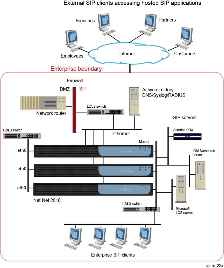
ME Sample Networks
Figure 21-1 illustrates a sample enterprise network with a single ME system.
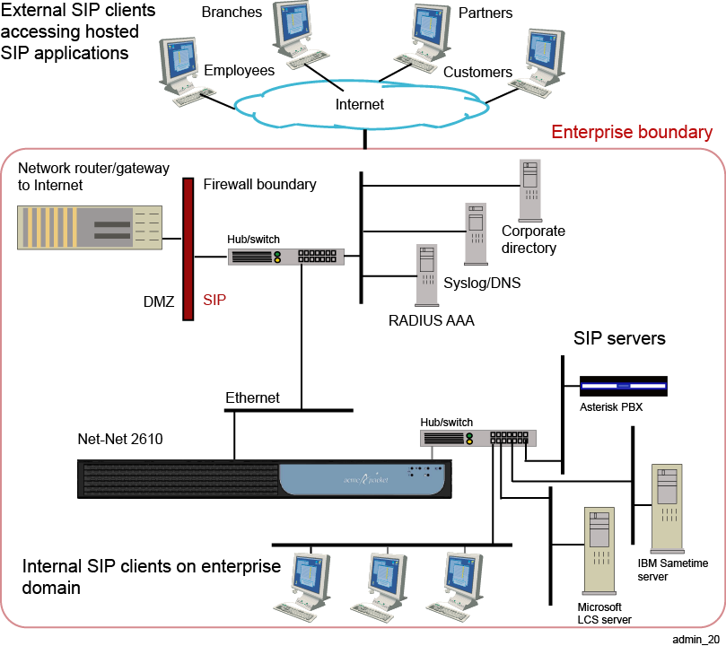
Figure 21-2 illustrates a sample enterprise that uses an ME cluster.
Configuring ME IP Interfaces
ME physical interfaces include multiple Ethernet 1000 Mbps auto-negotiation interfaces, such as eth0, eth1, eth2, and eth3. The number of interfaces depends on the specific platform you are using.
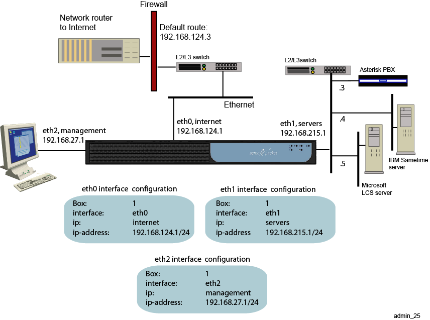
ME software uses IP objects, which are assigned a name by the system administrator, to uniquely identify IP connections. Each physical Ethernet interface can contain up to 255 uniquely named IP objects. Figure 21-3 illustrates a sample network with one named IP object on each physical Ethernet interface.
CLI Session for Eth0
The network on physical interface eth0 uses the IP object that the system administrator named internet. The internet object specifies the IP address that connects to the external Internet local gateway using a default route.
SIP>config cluster
config cluster>config box 1
config box 1>config interface eth0
config interface eth0>config ip internet
Creating ’ip internet'
config ip internet>set ip-address static 192.168.124.1/24
config ip internet>return

config interface eth0>config ip internet
config ip internet>set ip-address static 192.168.124.2/24
config ip internet>config routing
config routing>config route internetGateway
config route internetGateway>set destination default
config route internetGateway>set gateway 192.168.124.3
CLI Session for Eth1
The network on physical interface eth1 uses the IP object named servers. The static IP address points to the SIP destination servers on the same network subnet, connected over Ethernet switch.
SIP>config cluster
config cluster>config box 1
config box 1>config interface eth1
config interface eth1>config ip servers
config ip servers>set ip-address static 192.168.215.1/24
config ip servers>return
CLI Session for Eth2
The network on physical interface eth2 uses the defined IP object named management. The management object specifies the IP address over which management traffic is carried, such as remote CLI session over Telnet, or a ME Management System session.
SIP>config cluster
config cluster>config box 1
config box 1>config interface eth2
config interface eth2>config ip management
config ip internet>set ip-address static 192.168.27.1/24
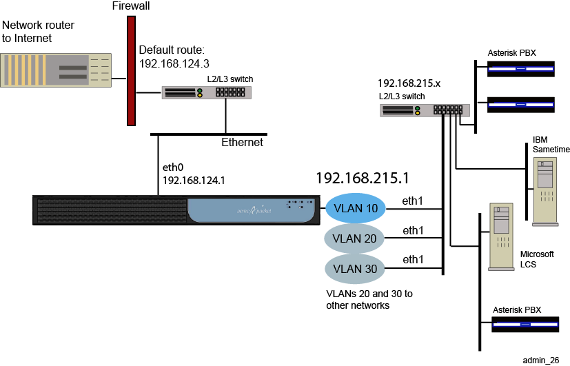
Creating VLANs
ME virtual LANs (VLANs) provide Layer 2 partitions to the communications servers. Creating one or more VLANs allows you to group LAN segments so that they appear to be on the same Layer 2 network. Each VLAN is identified by a VLAN ID, and ID must be unique within the physical ME system. This means that multiple logical ME systems (called VSPs) cannot use the same VLAN IDs. VLAN IDs can be in the range 1 to 4096.
Figure 21-4 illustrates a sample VLAN configuration.
CLI Session
The following CLI session configures the VLAN 10 network. VLAN 10 supports three separate physical IP networks, and all appearing as if they are on the same Layer2 network.
SIP>config cluster
config cluster>config box 1
config box 1>config interface eth1
config interface eth1>config vlan 10
Creating ’vlan10'
config vlan 10>config ip servers
Creating ’ip servers'
config ip servers>set ip-address static 192.168.215.1/24
config ip servers>return
Applying Routing and Classification Tags
The system uses classification tags to classify incoming traffic and routing tags to control the egress route for a specific service type. Tags allow the IP routing table in Session Manger to be segmented into multiple routing tables. Once an interface has a configured routing tag, the interface is removed from the ”null” (or system routing table).
When traffic comes arrives at an ME system on an identified interface, you can direct that traffic to a specific egress interface to the destination. This means that you would configure a classification-tag on the incoming interface that matches the routing-tag on the desired egress interface.
You can create multiple routing tags on the same named IP interface. However, only one classification tag is allowed per IP interface. Both routing and classification tags are case sensitive with the following configuration properties:
-
routing-tag: Associates all the routes configured on an interface with this routing-tag and creates a service route table based on the routing-tag for each service enabled on this interface. The routing-tag applies to the egress interface over which the ME forwards service traffic. Once a routing-tag is configured for an interface, the service routes associated with that interface are installed in the service route table associated with the routing-tag(s).
If you create an additional routing-tag for the interface with the name ”null,” the system installs the route in both the default service route table and the tag-specific service route table.
-
classification-tag: Creates a tag associated with inbound traffic on this interface. This means that you must configure a classification-tag on the ingress interface over which the ME domain initially receives the traffic, matching the routing-tag. (Classification tags in the session configuration routing-settings object also must match this routing tag set in the ip object.
Note:
You can also configure ingress or egress classification tags through the session-config routing-settings object. If this property is configured in both places, the routing-settings configuration takes precedence.
Figure 21-5 illustrates a sample network where routing and classification tags are configured on the ingress and egress ME interfaces, followed by sample configuration sessions for ingress and egress IP instances.
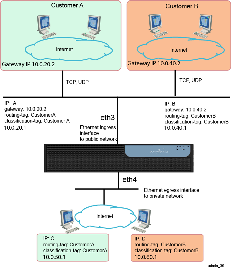
CLI Sessions for ”IP A” and ”IP B” Ingress Networks on Eth3
The following CLI sessions create the ingress side of the network illustrated in the image above, including the IP addresses, routing and classification tags, SIP settings, and a route to the IP using the gateways at IP addresses at 10.0.20.2 and 10.0.40.2. The ME uses classification tags to classify incoming traffic and routing tags to control the egress route. Configure a classification-tag on the incoming interface that matches the routing-tag on the egress interface.
SIP>config cluster
config cluster>config box 1
config box 1>config interface eth3
Creating ’interface eth3'
config interface eth3>config ip A
Creating ’ip A'
config ip A>set ip-address static 10.0.20.1/24
config ip A>set classification-tag CustomerA
config ip A>set routing-tag CustomerA
config ip A>config sip
config sip>set admin enabled
config sip>set nat-translation enabled
config sip>set udp-port 5060
config sip>set tcp-port 5060
config sip>return
config ip A>config icmp
config icmp>return
config ip A>config routing
config routing>config route default
Creating ’route default'
config route default>set gateway 10.0.20.2
config route default>return
config routing>return
config ip A>return

SIP>config cluster
config cluster>config box 1
config box 1>config interface eth3
Creating ’interface eth3'
config interface eth3>config ip B
Creating ’ip B'
config ip B>set ip-address static 10.0.40.1/24
config ip B>set classification-tag CustomerB
config ip B>set routing-tag CustomerB
config ip B>config sip
config sip>set admin enabled
config sip>set nat-translation enabled
config sip>set udp-port 5060
config sip>set tcp-port 5060
config sip>return
config ip B>config icmp
config icmp>return
config ip B>config routing
config routing>config route default
Creating ’route default'
config route default>set gateway 10.0.40.2
config route default>return
config routing>return
config ip B>return
CLI Sessions for ”IP C” and ”IP D” Egress Networks on Eth4
The following CLI sessions create the egress side of the network illustrated in the image above, including the IP addresses, routing and classification tags, SIP settings, and a default route. The ME uses classification tags to classify incoming traffic and routing tags to control the egress route. Configure a classification-tag on the incoming interface that matches the routing-tag on the egress interface.
SIP>config cluster
config cluster>config box 1
config box 1>config interface eth4
Creating ’interface eth4'
config interface eth4>config ip C
Creating ’ip C'
config ip C>set ip-address static 10.0.50.1/24
config ip C>set classification-tag CustomerA
config ip C>set routing-tag CustomerA
config ip C>config sip
config sip>set admin enabled
config sip>set nat-translation enabled
config sip>set udp-port 5060
config sip>set tcp-port 5060
config sip>return
config ip C>config icmp
config icmp>return
config ip C>config routing
config routing>config route default
Creating ’route default'
config route default>set destination default
config route default>return

SIP>config cluster
config cluster>config box 1
config box 1>config interface eth4
Creating ’interface eth4'
config interface eth4>config ip D
Creating ’ip D'
config ip D>set ip-address static 10.0.60.1/24
config ip D>set classification-tag CustomerB
config ip D>set routing-tag CustomerB
config ip D>config sip
config sip>set admin enabled
config sip>set nat-translation enabled
config sip>set udp-port 5060
config sip>set tcp-port 5060
config sip>return
config ip D>config icmp
config icmp>return
config ip D>config routing
config routing>config route default
Creating ’route default'
config route default>set destination default
config route default>return
Notes on Routing and Classification Tags
-
Separate routing tables are maintained for the SIP and media service.
-
IP interfaces without SIP ports enabled will not appear in the SIP table.
-
IP interfaces without media ports enabled will not appear in the media table.
-
SIP or media traffic that is classified by a tag will only use the routing information and interfaces that have been configured with that routing tag.
-
An address of record (AOR) will be assigned an ingress tag IF the REGISTER for that AOR ingresses on an IP interface with a configured classification-tag.
-
Matches a policy or registration-plan that applies a session configuration that has the ingress-classification-tag property configured. This overwrites the IP interface classification-tag, if configured.
-
Matches a calling-group. The classification-tag for the calling-group is only applied if a tag has not been assigned using the IP or session configuration.
-
Traffic can be assigned an egress tag as follows:
-
From an ingress tag.
-
From a matching policy or dial-plan that applies a session configuration that has the egress-classification-tag configured. This overwrites the classification-tag configured on the interface.
-
From a server or carrier with the routing-tag configured, overwriting all other tags.
-
Related Commands
To assist troubleshooting, use the following commands from the ME prompt to display information about tag-routing.
-
show services-routing: Displays routing tables for all tags.
-
show services-routing-tables: Displays all configured tags.
-
service-route-lookup: To view the destination where the ME routed a call.
Configuring Overlapping IP Networks and Tag Routing
A preferred method for creating networks, with overlapping IPs is to configure VLANs with routing tags. A routing tag associates all the routes configured on an interface and creates a service route table based on the tag for each service enabled the interface. Routing tags apply to the egress interface over which the ME forwards service traffic.
To perform tag routing, do the following:
-
Configure a classification-tag on the ingress interface over which the ME initially receives service traffic. The classification tag must match the configured routing-tag; each IP interface can have multiple routing tags.
-
Set the egress-classification-tag property under the session-config/routing-settings when sending service traffic to servers and carriers.
CLI Session for Ethernet Public and Private Sides of Network
The following CLI session configures the ME public IP Ethernet interface and SIP settings.
SIP>config cluster
config cluster>config box 1
config box 1>config interface eth3
Creating ’interface eth3'
config interface eth3>config ip public
Creating ’ip public'
config ip public>set ip-address static 10.0.10.1/24
config ip public>config sip
config sip>set admin enabled
config sip>set nat-translation enabled
config sip>return
The following CLI session configures the ME private IP Ethernet interface and SIP settings.
SIP>config cluster
config cluster>config box 1
config box 1>config interface eth4
Creating ’interface eth4'
config interface eth4>config ip private
Creating ’ip private'
config ip private>set ip-address static 10.0.20.1/24
config ip private>config sip
config sip>set admin enabled
config sip>set nat-translation enabled
config sip>return
CLI Sessions for Customer-A and Customer-B Networks
The following CLI sessions create the VLANs to the Customer-A and Customer-B networks, including the IP addresses, routing and classification tags, SIP settings, and a route to the IP using the gateways at IP addresses at 10.0.1.50 and 10.0.1.60. The ME uses classification tags to classify incoming traffic and routing tags to control the egress route. Configure a classification-tag on the incoming interface that matches the routing-tag on the egress interface.
config interface eth3>config vlan 10
Creating ’vlan 10'
config vlan 10>config ip 10.0.1.1
Creating ’10.0.1.1'
config ip 10.0.1.l>set ip-address static 10.0.1.1/24
config ip 10.0.1.l>set classification-tag vlan10
config ip 10.0.1.1>set routing-tag vlan10
config ip 10.0.1.1>config sip
config sip>set nat-translation enabled
config sip>set udp-port 5060
config sip>set tcp-port 5060
config sip>return
config ip 10.0.1.1>config icmp
config icmp>return
config ip 10.0.1.1>config routing
config routing>config route default
Creating ’route default'
config route default>set gateway 10.0.1.50
config route default>return
config routing>return
config ip 10.0.1.1>return

config interface eth3>config vlan 20
Creating ’vlan 20'
config vlan 20>config ip 10.0.1.1
Creating ’10.0.1.1'
config ip 10.0.1.l>set ip-address static 10.0.1.1/24
config ip 10.0.1.l>set classification-tag vlan20
config ip 10.0.1.1>set routing-tag vlan20
config ip 10.0.1.1>config sip
config sip>set nat-translation enabled
config sip>set udp-port 5060
config sip>set tcp-port 5060
config sip>return
config ip 10.0.1.1>config icmp
config icmp>return
config ip 10.0.1.1>config routing
config routing>config route default
Creating ’route default'
config route default>set gateway 10.0.1.60
config route default>return
config routing>return
config ip 10.0.1.1>return
CLI Session for the Internal Private Network
The following CLI session creates the VLAN to the internal private network, including the private IP address, routing and classification tags, SIP settings, and a default route to the public IP interface at 10.0.20.1. The ME uses classification tags to classify incoming traffic and routing tags to control the egress route. Configure a classification-tag on the incoming interface that matches the routing-tag on the egress interface.
config interface eth4>config vlan 30
Creating ’vlan 30'
config vlan 10>config ip 10.0.20.1
Creating ’10.0.20.1'
config ip 10.0.20.l>set ip-address static 10.0.20.1/24
config ip 10.0.20.l>set classification-tag MAIN
config ip 10.0.20.1>set routing-tag MAIN
config ip 10.0.20.1>config sip
config sip>set nat-translation enabled
config sip>set udp-port 5060
config sip>set tcp-port 5060
config sip>return
config ip 10.0.20.1>config icmp
config icmp>return
config ip 10.0.20.1>config routing
config routing>config route default
Creating ’route default'
config route default>set destination default
config route default>return
config routing>return
config ip 10.0.1.1>return
CLI Session for the session-config-pool
The following CLI session creates two session configuration entries for handling egress traffic from Customer-A and Customer-B to the ME. The session-config-pool is for any traffic routed to the private network. The egress-classification-tag property, which needs to match the appropriate VLAN routing-tag on VLAN 30, selects the interface to the private network.
config>config vsp session-config-pool
config session-config-pool>config entry "Customer-A"
Creating entry ”Customer A”
config entry ”Custom A”>config routing-settings
config routing-settings>set egress-classification-tag MAIN
config routing-settings>return
config entry ”Custom A”>return
config session-config-pool>config entry "Customer-B"
Creating entry ”Customer B”
config entry ”Custom B”>config routing-settings
config routing-settings>set egress-classification-tag MAIN
Configuring VRRP
The Virtual Router Redundancy Protocol (VRRP) provides redundancy of IP interfaces within an ME cluster. The configuration for IP interfaces includes a list of box/interface pairs. The first pair in this list is the primary interface. The second pair in the list is the backup interface and will take over if the primary goes down. You can configure additional levels of redundancy by specifying more box/interface pairs of lower priority. Priority is based on the positioning of the set host-interface command.
VRRP also provides redundancy of master services within a cluster. Each master service, including directory, database, and accounting, can be configured with a list of locations (box numbers within the cluster). The first location, such as box 1, is the primary; the second location (box 2) takes over if the primary fails. Specifying more locations in the list creates additional levels of redundancy.
The following image illustrates a sample network where VRRP reroutes traffic around a failed interface.
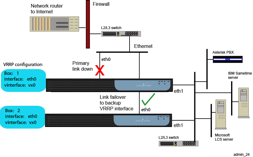
If the master VRRP interface becomes unavailable, the VRRP election protocol enables a backup VRRP interface to assume mastership using the next prioritized interface in the list. However, if the original master VRRP interface (the interface with the highest priority) should once again become available, VRRP returns mastership to that interface.
See RFC 2338, Virtual Router Redundancy Protocol, for detailed information about this protocol.
CLI Session
The following CLI session creates two VRRP virtual interfaces (vx0 and vx1), and configures the physical host interfaces associated with each vinterface. On the vx0 interface, physical interface eth0 on box 1 will failover to eth0 on box 2, and then to eth0 on box 3. Note that each VRRP interface has its own IP (or VLAN) configuration.
SIP>config cluster
config cluster>config vrrp
config vrrp>config vinterface vx0
config vinterface vx0>set host-interface cluster box 1 interface eth0
config vinterface vx0>set host-interface cluster box 2 interface eth0
config vinterface vx0>set host-interface cluster box 3 interface eth0
config vinterface vx0>config ip name
Creating ’ip name'
config ip name>set ip-address static 1.1.1.1/24
config ip name>return
config vinterface vx0>return

config vrrp>config vinterface vx1
config vinterface vx1>set host-interface cluster box 3 interface eth1
config vinterface vx1>set host-interface cluster box 4 interface eth1
config vinterface vx1>config ip name
Creating ’ip name'
config ip name>set ip-address static 1.1.1.2/24
config ip name>return
config vinterface vx0>return
See RFC 2338, Virtual Router Redundancy Protocol, for detailed information about VRRP.
When configuring VRRP backing interfaces, Oracle recommends you have no more than two different MEs on the host list. You can, however, have more than one interface configured per box without any problems.
Here are some examples to illustrate acceptable and not acceptable configurations.
Not acceptable: There are interfaces from three different MEs listed for this VX interface. Oracle recommends you only have two MEs backing a VX.
config vrrp
 config vinterface vx10
  set group 1
  set host-interface cluster\box 1\interface eth1
  set host-interface cluster\box 2\interface eth1
  set host-interface cluster\box 3\interface eth1
  config ip 10.1.1.1
  return
 return
return
Not acceptable: There are interfaces from three different MEs listed for this VX interface and preempt=true is configured. This configuration is not supported at this time and will result in inconsistent behavior for the VX interface.
config vrrp
 config vinterface vx10
  set group 1
  set preempt true
  set host-interface cluster\box 1\interface eth1
  set host-interface cluster\box 2\interface eth1
  set host-interface cluster\box 3\interface eth1
  config ip 10.1.1.1
  return
 return
return
Acceptable: There are only two MEs listed as hosts for this VX.
config vrrp
 config vinterface vx10
  set group 1
  set host-interface cluster\box 1\interface eth1
  set host-interface cluster\box 2\interface eth1
  config ip 10.1.1.1
  return
 return
return
Acceptable: There are only two MEs listed as hosts for this VX, but each ME has two host interfaces configured on it.
config vrrp
 config vinterface vx10
  set group 1
  set host-interface cluster\box 1\interface eth1
  set host-interface cluster\box 1\interface eth2
  set host-interface cluster\box 2\interface eth1
  set host-interface cluster\box 2\interface eth2
  config ip 10.1.1.1
  return
 return
return
In either of these last two acceptable examples, it is okay to configure preempt=true.
Configuring Signaling Failover
The ME systems use signaling failover to preserve signaling sessions in a high-availability cluster. The cluster master-service maintains the signaling state of connections cluster-wide. With signaling failover, the signaling state information is transferred to the ME system taking over the signaling stream.
Note:
The call must be connected (at the SIP level) in order for signaling failover to take place. Signaling states prior to the ”connected” state are not maintained in the cluster wide state table. Additionally, for TCP and TLS connections, the user agent must re-establish the connection once the failover has occurred. Since TCP/TLS are connection-oriented protocols, signaling state information is not maintained across failover. If TLS is used, the appropriate certificate must be loaded on the ME systems in the cluster.Signaling information is maintained so that accurate call logs are recorded at the end of the call.
Note:
If there is a failure at the ME system holding the call log database, information will be lost.Use the ME show signaling-sessions command to display failover state information.
CLI Session
SIP>config cluster
config cluster>set share-signaling-entries true
The share-signaling-entries property specifies whether or not all ME systems in a cluster exchange active SIP session information. When set to true, the ME systems exchange data. If the primary link then goes down, a backup link can use SIP session information from the primary device to handle existing calls.
The share-signaling-entries property should be set to true if you have configured VRRP (to provide the redundancy support). If you have VRRP enabled and configured, and if share-signaling-entries is set to true, signaling failover can take place.
Configuring Web Interface Settings
The Web object enables the Web server, providing access to the ME Management System graphical user interface. If you want to view SNMP traps through the GUI, you must also enable the server as a trap target. You enable and configure Web services on Ethernet and VLAN interfaces.
Configuring Web Services
The web-service object enables the Web Services Definition Language (WSDL). WSDL is an XML-based language for describing Web services, and how to access them, in a platform-independent manner. Simple Object Access Protocol (SOAP) is the communication protocol used for communication between applications, based on XML.
A WSDL document is a set of definitions that describe how to access a web service and what operations it will perform. The ME uses it in combination with SOAP and XML Schema to allow a client program connecting to a web service to determine available server functions. The actions and data types required are embedded in the WSDL file, which then may be enclosed in a SOAP envelope. The SOAP protocol supports the exchange of XML-based messages with the ME system using HTTPS.
CLI Session
SIP>config cluster
config cluster>config box 1
config box 1>config interface eth0
config interface eth0>config ip boston1
config ip boston1>config web-service
config web-service>set admin enabled
config web-service>set protocol https 443 0 ”vsp tls certificate OS-E.company.com”
For detailed information on WSDL, refer to the Net-Net OS-E – Management Tools.
Enabling ICMP and Setting Rate Limits
The Internet Control Message Protocol (ICMP), defined in RFC 792, is a TCP/IP protocol that determines whether a destination is unreachable. Using error and control messages between an host and an Internet gateway, ICMP verifies the validity of an IP address.
You can limit the rate at which ICMP messages are received on the ME system by setting ICMP rate and burst limits that prevent flooding of ICMP messages on the network. The rate setting is the maximum number of ICMP destination unreachable messages that the device can receive per second; the burst setting is the rate by which the number of ICMP messages that are discarded per second. Configuring the burst setting to a number lower than the rate setting will prevent ICMP message flooding.
CLI session
The following CLI session enables ICMP on the specified interface and sets ICMP rate and burst limits.
SIP>config cluster box 1
config box 1>config interface eth0
config interface eth0>config ip boston1
Creating ’ip boston1'
config ip boston1>config icmp
config icmp>set admin enabled
config icmp>set limit 12 6
Enabling NTP and BOOTP Servers
By default, Network Time Protocol (NTP) and BOOTP services are enabled. The ME system uses NTP to synchronize time with external and local clocks using an NTP server, and the BOOTP protocol to allow an ME network client to learn its own IP address and boot information from a BOOTP server.
If addition to configuring NTP and BOOTP clients, you need to ensure that the NTP and BOOTP services are enabled on ME IP interfaces.
CLI Session
The following session enables BOOTP services on the specified ME IP interface and port number.
SIP>config cluster box 1
config box 1>config interface eth0
config interface eth0>config ip boston1
Creating ’ip boston1'
config ip boston1>config bootp-server
config bootp-server>set admin enabled
config bootp-server>set port 67
The following session enables NTP services on the specified ME IP interface.
SIP>config cluster box 1
config box 1>config interface eth0
config interface eth0>config ip boston1
Creating ’ip boston1'
config ip boston1>config ntp-server
config ntp-server>set admin enabled
Configuring the Network Time Protocol (NTP) Clients
The ME system uses the Network Time Protocol (NTP) to synchronize time with external and local clocks. Synchronized time across a network is important for critical functions such as packet and event time stamps or certificate validation.
You can configure an external NTP server to synchronize network time on the ME system. When you configure NTP, the system receives packets from the external NTP server that updates the local ME clock at specified NTP poll intervals.
CLI Session
The following session configures an external NTP server on the local ME NTP client. The session enables the ME NTP client, specifies the IP address of the remote NTP server, and the sets the poll-interval (in minutes) between network time updates from the NTP server.
config box>config ntp-client
config ntp-client>set admin enabled
config ntp-client>set server 192.168.23.76
config ntp-client>set poll-interval 5
Configuring the Bootstrap Protocol (BOOTP) Clients
The BOOTP commands allow you to configure the Bootstrap Protocol (BOOTP) client and server settings in an ME network cluster. BOOTP, described in RFC 951, is the Internet protocol that allows a network client to learn its own IP address and boot information from a BOOTP server.
In a network cluster, a BOOTP client requests its own IP address from the ME BOOTP server, as well as the IP address of the BOOTP server itself using the hardware MAC address. The BOOTP server responds to BOOTP client requests over the configured server port.
If a BOOTP session cannot be established between the ME client and server, BOOTP closes the session across the BOOTP interfaces after 60 seconds.
CLI Session
The following session configures a bootp client on the ME system. The session enables the bootp client, and sets the known bootp client and server ports for bootp requests and responses. UDP port 68 is the known bootp client port; UDP port 67 is the known bootp server port.
config box>config bootp-client
config bootp-client>set admin enabled
config bootp-client>set client-port eth1 68
config bootp-client>set server-port eth0 67
Configuring Session Initiation Protocol
For SIP applications running over Oracle networks, you need to enable the Session Initiation Protocol (SIP) on the ME IP interfaces. By default, the SIP protocol is enabled. However, you do need to configure the SIP operation mode, set the UDP, TCP, and TLS ports to use when listening for SIP messages, and include any certificates (generated and imported from a certificate authority) to be associated with the SIP interface.
-
In proxy mode, the ME system only participates in SIP messages. Once the call is established, the phones send their voice traffic directly to each other without involving the proxy. SIP proxies offload tasks and simplify the implementation of end station telephones.
-
The B2BUA is a SIP-based logical entity that receives and processes INVITE messages as a SIP User Agent Server (UAS). It also acts as a SIP User Agent Client (UAC) that determines how the request should be answered and how to initiate outbound calls. Unlike SIP proxy mode, the B2BUA maintains the call state and participates in all call requests.
-
A stateless proxy forwards every request it receives and discards information about the request message once the message has been forwarded.
CLI Session
The following CLI session sets the SIP operation mode to ”proxy.”
SIP>config vsp
config vsp>config default-session-config
config default-session-config>config sip-settings
config sip-settings>set mode proxy
The following CLI session enables the SIP protocol on the specified IP interface, specifies the TCP, UDP and TLS ports to use when listening for SIP messages, and includes a certificate from an authorized certificate authority (CA).
SIP>config cluster
config cluster>config box 1
config box 1>config interface eth0
config interface eth0>config ip boston1
Creating ’ip boston1'
config ip boston1>config sip
config sip>set admin enabled
config sip>set nat-translation enabled
config sip>set nat-add-received-from enabled
config sip>set udp-port 5060
config sip>set tcp-port 5060
config sip>set tls-port 5061
config sip>set certificate vsp tls certificate os-e.net.com
Load Balancing Across Media Engine Interfaces
Load balancing of SIP processing across interfaces requires both headed and backing interfaces.
The headend interface is the central distribution point. It does not perform SIP processing, it only forwards the calls to its configured backing interfaces. When you configure a SIP phone, configure the phone directly to the headend interface. To configure an IP interface as a headend interface, configure the sip object with backing interfaces. An interface is considered a headend interface if it has configured backing interfaces.
The backing-interfaces are identified within this sip object. In the backing-interface property, you reference previously configured IP interfaces. The backing interface is the location at which the ME terminates TCP and TLS connections (and where UDP transport messages arrive) and handles SIP processing. The ME uses round-robin load-balancing to distribute message across the configured backing interfaces.
To correctly configure load-balancing for SIP processing, you must do the following:
-
Configure the IP interfaces that will be used for both the headend and backing interfaces.
-
The SIP properties of the backing interfaces must match those of the head interface. For example, the interfaces must all use the same port assignments, and if you are using TLS, they must all use the same certificate.
-
You must enable the master services registration object so that the interfaces can share the registration database.
To verify your configuration, first ensure that all SIP properties match. From the CLI at the ME system that hosts the headend, execute the show load-balance command. This lists all associated backing interfaces (and statistics). From each box hosting a backing interface, execute show backing-interface to display configuration and statistics information.
CLI Session
SIP>config cluster
config cluster>config box 1
config box 1>config interface eth0
config interface eth0>config ip boston1
config ip boston1>config sip
config sip>set admin enabled
config sip>set nat-translation enabled
config sip>set udp-port 5060
config sip>set tcp-port 5060
config sip>set tls-port 5061
config sip>set certificate ”vsp tls certificate os-e.companyA.com”
config sip>set backing-interface ”cluster box 1 interface eth0 ip backing1”
config sip>set backing-interface ”cluster box 1 interface eth1 ip backing2”
config sip>set backing-interface ”cluster box 2 interface eth0 ip
Configuring Media Port Pools
The media-ports object defines the ports and port ranges to assign to media streams on an Ethernet interface, such as NAT, media anchoring, and media recording.
CLI Session
The following CLI session enables the media-ports object, sets the starting port number, sets the total number of ports available for media streams, and enables the monitoring of idle ports (so that no traffic is sent to idle ports that are part of the media pool).
SIP>config cluster
config cluster>config box 1
config box 1>config interface eth0
config interface eth0>config ip boston1
Creating ’ip boston1'
config ip boston1>config media-ports
config media-ports>set admin enabled
config media-ports>set base-port 20000
config media-ports>set count 5000
config media-ports>set idle-monitor enabled
Supported WebRTC Protocols
This section describes how to configure the Interactive Connectivity Establishment (ICE), Session Traversal Utilities for NAT (STUN), and Traversal Using Relay NAT (TURN) protocols in a WebRTC implementation.
What is Interactive Connectivity Establishment?
ICE is a protocol that establishes network paths for UDP-based media streams. It is an extension of the SDP offer/answer model and works by discovering and including all possible media transport addresses (known as candidates) in the SDP. Once SDPs are exchanged, ICE tests all possible media paths using the Session Traversal Utilities for the NAT (STUN) protocol as connectivity checks. Once the connectivity checking completes, the ICE agents settle on a final candidate pair to use for media transmission. The ME supports ICE on a per call-leg basis, meaning it can act as both the offering and answering ICE agent to satisfy this WebRTC requirement.
In addition to ICE, the ME also supports augmented ICE. In ICE the ME strips the candidates from the SDP while in augmented ICE the ME preserves all candidates received from a WebRTC endpoint. This provides the WebRTC endpoints the option to either anchor media on the ME or not.
For more information on ICE, visit http://tools.ietf.org/html/rfc5245.
What is Session Traversal Utilities for NAT?
In addition to connectivity checking, ICE relies heavily on STUN to discover all possible media candidates. During this candidate gathering phase, ICE agents perform STUN requests to discover their public IP addresses when behind a NAT device. The ME can be configured as a STUN server to satisfy these initial STUN requests.
For more information on STUN, visit http://www.ietf.org/rfc/rfc3489.
What is Traversal Using Relay NAT?
The TURN protocol assists clients located behind NAT devices to reach peers. In cases where clients and peers cannot create a direct communication path (for example, if both endpoints are behind individual NATs), it is necessary for an intermediate network device to relay data. The ME TURN Server acts as a communication-enabling alternative for such cases, relaying data between the NAT-hidden clients. When used with ICE, the ME TURN Server relay transport addresses are included in SDP ICE candidates received from clients. For more information on TURN, visit http://tools.ietf.org/search/rfc5766.
Session Traversal Utilities for NAT Required Methods
The following STUN methods are required for the ME's TURN Support:
-
Allocate
-
Refresh
-
Send
-
Data
-
CreatePermission
-
ChannelBind
Session Traversal Utilities for NAT Required Attributes
-
CHANNEL-NUMBER
-
LIFETIME
-
XOR-PEER-ADDRESS
-
DATA
-
XOR-RELAYED-ADDRESS
-
EVEN-PORT
-
REQUESTED-TRANSPORT
-
DONT-FRAGMENT
-
RESERVATION-TOKEN
Non-Session Traversal Utilities for NAT Traversal Using Relays NAT Message
The ME supports the non-STUN ChannelData TURN message. This message carries application data between the TURN client and the server. Use of this message is optional for the client but required for the server if a channel has been bound to a remote peer.
Purging Traversal Using Relays Around the NAT Allocations
The turn-allocation-purge action allows you to manually remove TURN Allocations. Per RFC5766, TURN clients that no longer want to use an Allocation are encouraged to delete the Allocation via a TURN Refresh request with a requested lifetime of 0. However, some TURN clients currently do not remove Allocations and these remain in the ME until they expire.
Note:
Ensure you remove only unused Allocations. Removing valid and in-use Allocations disrupts a WebRTC call using the ME's TURN server.Syntax
turn-allocation-purge [turn-client]
Arguments
-
[turn-client]: The TURN client's IP address and port.
Note:
By default, the turn-allocation-purge action purges all TURN Allocations, unless otherwise specified.Media Engine Encryption
Secure Real-Time Transport Protocol (SRTP) is secure Real-Time Transport Protocol (RTP) designed to provide encryption, authentication, and integrity to RTP streams. Used along with Source Description RTCP (SDES), encryption keys are exchanged in the SDP offer and answer using the crypto attribute. The ME supports SDES-SRTP encryption and decryption on a per call-leg basis to satisfy this WebRTC requirement.
For more information on SDES, visit http://tools.ietf.org/html/rfc4568.
In addition to SDES-SRTP, the ME also supports Datagram Transport Layer Security (DTLS) as a method for encryption. DTLS works similarly to SDES-SRTP in that encryption keys are exchanged in the SDP offer and answer using the crypto attribute and the ME supports DTLS on a per call-leg basis.
For more information on DTLS, visit http://tools.ietf.org/html/rfc4347.
Data Channel Support
The ME supports data channels for anchored media.
Data channels use the SCTP protocol as a generic transport service which allows web browsers and native mobile applications to exchange non-media data between peers.
For more information on data channels, visit https://tools.ietf.org/html/draft-ietf-rtcweb-data-channel-11.
Note:
You must have the session-config > media > anchor property set to enabled for data channels to work.Configuring Interactive Connectivity Establishment
To configure ICE on the ME, you must enable session-wide media anchoring.
You must also enable symmetric RTP, which returns RTP based on the source IP address and UDP port in the received RTP. NAT modifies data in the IP header only and the SDP payload is left unchanged. By using the source IP address and UDP port from the received RTP, the ME sends traffic back to the NAT device instead of the untranslated addresses in the SDP.
In addition to these session-wide settings, you must also configure ICE for incoming and outgoing WebRTC sessions.
To enable system-wide media anchoring and symmetric RTP:
-
Click the Configuration tab and select either default-session-config or session-config-pool > entry.
-
Click Configure next to media.
-
anchor: Set to enabled to enable media anchoring for this media session. Media anchoring forces the SIP media session to traverse the ME.
-
Click Configure next to nat-traversal.
-
symmetricRTP: Set to true to enable symmetric RTP for this media session. When enabled, symmetric RTP returns RTP based on the source IP address and UDP port in the received RTP. NAT modifies data in the IP header only and the SDP payload is left unchanged.
-
Click Set. You are returned to the media object.
-
Click Set. Update and save the configuration.
To enable ICE for incoming WebRTC sessions:
-
Click the Configuration tab and select either default-session-config or session-config-pool > entry.
-
Click Configure next to in-ice-settings.
-
admin: Set to enabled to enable ICE on this call leg.
-
connectivity-check-max-retransmits: Specify the number of times the ME retransmits ICE STUN connectivity checks before labeling a candidate pair as Failed. To achieve maximum interoperability with Chrome, set this value to no less than 200.
-
Click Set. Update and save the configuration.
To enable ICE for outgoing WebRTC sessions:
-
Click the Configuration tab and select either default-session-config or session-config-pool > entry.
-
Click Configure next to in-ice-settings.
-
admin: Set to enabled to enable ICE on this call leg.
-
delay-stun-responses: (Advanced) Set to enabled so that the ME does not respond to STUN until the 200 OK is received.
Note:
To view Advanced properties, click the Show advanced button. -
suppress-re-invites: (Advanced) Set to enabled. When enabled so that the ME does not send a re-INVITE when ICE completes successfully.
-
Click Set. Update and save the configuration.
Configuring Augmented Interactive Connectivity Establishment
The ME supports augmented ICE. In ICE the ME strips the candidates from the SDP while in augmented ICE the ME preserves all candidates received from a WebRTC endpoint. This provides the WebRTC endpoints the option to either anchor media on the ME or not.
If you are configuring the ME for augmented ICE you must complete the configuration procedure for ICE plus some additional configuration. For details on configuring ICE, see "Configuring Interactive Connectivity Establishment".
Note:
By default, augmented ICE is disabled on the ME. If you are using augmented ICE for a particular session, enable it on that named session-config-pool > entry only. Leave the default-session-config object's augmented ICE setting disabled so as not to affect all named sessions, which can cause an adverse negative impact.To configure augmented ICE:
-
Click the Configuration tab and select either default-session-config or session-config-pool > entry.
-
Click Configure next to media.
-
augmented-ice: Set to enabled to enable augmented ICE.
-
Click Set. You are returned to the media object.
-
Click Configure next to in-encryption.
-
mode: Select pass-thru from the drop-down list.
-
Click Set. You are returned to the media object.
-
Click Configure next to out-encryption.
-
mode: Select pass-thru from the drop-down list.
-
Click Set. Update and save the configuration.
Configuring Trickle Interactive Connectivity Establishment
The ME supports trickle ICE, a draft extension to RFC 5245 that allows ICE agents to incrementally exchange remote candidate information. Trickle ICE support considerably reduces call setup time by allowing ICE to run before the candidate harvesting phase has completed by sending empty or partial media candidate lists in the SDP.
To configure trickle ICE:
-
Click the Configuration tab and select either default-session-config or session-config-pool > entry.
-
Click Configure next to in-ice-settings.
-
trickle-ice: Set to enabled or disabled to determine if trickle ICE is offered and supported on each call leg.
-
Click Configure next to out-ice-settings.
-
trickle-ice: Set to enabled or disabled to determine if trickle ICE is offered and supported on each call leg.
-
Click Set. Update and save the configuration.
Three show commands allow you to view trickle ICE information: show ice-local-candidates, show ice-remote-candidates, show ice-candidate-pair-status.
show ice-local-candidates
Displays ICE information for the local candidates used by each state machine.
Sample Output
SIP>show ice-local-candidates
session-id       leg checklist  transport  componentID type priority foundation
-----------      --- ---------  ---------  ----------- ---- -------- -----------
0x8c4ef6081de8c26 1 172.44.10.55:20676 UDP 1 host 2130706431 1172.44.10.55:20677
Properties
-
session-id: The ID of the session that owns the ICE state machine.
-
leg: The call-leg on which the ICE state machine is running.
-
checklist: The checklist number that owns the candidate. This is also known as the media description index.
-
transport: The IP, port, and transport protocol of the candidate.
-
componentID: The ICE component ID. This value is an integer.
-
type: The ICE candidate type. This can be either host, srflx, prflx, or relay.
-
priority: The candidate priority.
-
foundation: The foundation string.
show ice-remote-candidates
Displays ICE information for the remote candidates received from the remote peer.
Sample Output
SIP>show ice-remote-candidates
session-id leg checklist transport componentID type priority foundation
---------- --- --------- --------- --------------- -------- ----------
0x8c4ef6081de8c26 1 0 172.44.10.57:22656 UDP 1 host 2130706431 1
172.44.10.57:22657 UDP 2
Properties
-
session-id: The ID of the session that owns the ICE state machine.
-
leg: The call-leg on which the ICE state machine is running.
-
checklist: The checklist number that owns the candidate. This is also known as the media description index.
-
transport: The IP, port, and transport protocol of the candidate.
-
componentID: The ICE component ID. This value is an integer.
-
type: The ICE candidate type. This can be either host, srflx, prflx, or relay.
-
priority: The candidate priority.
-
foundation: The foundation string.
show ice-candidate-pair-status
Displays information and state for each ICE candidate pair.
Sample Output
SIP>show ice-remomte-candidates
session-id leg checklist transport componentID type priority foundation
---------- --- --------- --------- ----------- ---- -------- ----------
0x8c4ef6081de8c26 1 0 172.44.10.57:22656 UDP 1 host 2130706431 1
Properties
-
session-id: The ID of the session that owns the ICE state machine.
-
leg: The call-leg on which the ICE state machine is running.
-
checklist: The checklist number that owns the candidate. This is also known as the media description index.
-
transport: The IP, port, and transport protocol of the candidate.
-
componentID: The ICE component ID. This value is an integer.
-
type: The ICE candidate type. This can be either host, srflx, prflx, or relay.
-
priority: The candidate priority.
-
foundation: The foundation string.
show ice-candidate-pair-status
Displays information and state for each ICE candidate pair.
Sample Output
SIP>show ice-candidate-pair-status
session-id leg checklist local remote state componentID nominated
---------- --- --------- ----- ------ ----- ----------- ---------
0x8c4ef6081de8c26 10 172.44.10.55:20676 UDP 172.44.10.57:22656 UDP Succeeded1 true
Properties
-
session-id: The session ID on which ICE is running.
-
leg: The call leg on which ICE is running.
-
checklist: The checklist that owns the candidate pair. This is also known as the media description index.
-
local: The local candidate in the pair.
-
remote: The remote candidate in the pair.
-
state: The pair state. This can be either Frozen, Waiting, Succeeded, or Failed.
-
componentID: The componentID of the pair. This value is an integer.
-
nominated: Specifies whether or not this pair has been nominated for media transmission.
Configuring Session Traversal Utilities For the NAT
In addition to an ICE server, the ME can also be configured as a STUN server.
To configure the ME as a STUN server:
-
Click the Configuration tab and select the cluster > box > interface > ip object.
-
Click Configure next to stun-server.
-
admin: Set to enabled to enable the ME as a STUN server.
-
Click Add port to configure a port for the STUN server.
-
transport: Select from the drop-down list the transport protocol over which STUN messages are exchanged between a SIP endpoint and the ME STUN server. Valid values UDP, TCP, and TLS. The default value is UDP.
-
port: Specify the port over which STUN messages are exchanged between a SIP endpoint and the ME STUN server. The default value is 3478.
-
Click Create. You are returned to the stun-server object.
-
Click Set. Update and save the configuration.
For more information on the stun-server object, see the Oracle Communications WebRTC Session Controller Media Engine Object Reference.
Configuring Traversal Using Relay NAT
To enable the TURN server on the ME, you must enable STUN and configure several propreties within stun-server object.
To enable TURN:
-
Click the Configuration tab and select the cluster > box > interface > ip object on which you are configuring TURN.
-
Click Configure next to stun-server.
-
admin: Set to enabled to enable STUN.
-
allow-turn: Set to enabled.
-
relay-interface: Select an interface provisioned with media ports.
-
ltc-authentication-realm: Specify the realm to use for STUN LTC authentication.
-
ltc-authentication-username: Specify a username for STUN LTC authentication.
-
ltc-authentication-password: Specify a password for STUN LTC authentication.
-
Click Set. Update and save the configuration.
Three show commands allow you to view TURN server information: show turn-allocations, show turn-destinations, show stun-server.
show turn-allocations
Provides information for each TURN client allocated server relay port. WebRTC endpoints typically allocate a relay port for each media stream.
Sample Output
SIP>show turn-allocations
server-port: 172.44.10.60:3478
user: TurnMike@TurnRealm
client: 10.1.26.32:56863
client-transport: UDP
relay-port: 172.44.10.60:20975
relay-transport: UDP
destination-count: 1
client-to-peer-packets: 61489
client-to-peer-bytes: 5822176
peer-to-client-packets: 61585
peer-to-client-bytes: 5512977
bandwidth-max: 150 kbits-per-second
allocation-time: 07:12:02.147705 Tue 2014-01-21
duration: 1177 seconds
remaining: 503 seconds
Properties
-
server-port: The IP and port of the TURN server listener.
-
user: The user and realm of TURN LTC.
-
client: The IP and port of the TURN client.
-
client-transport: The transport method used for client/server communication.
-
relay-port: The IP and port of the TURN relay for this Allocation.
-
relay-transport: The transport method used for server/peer communication.
-
destination-count: The number of TURN destinations for this Allocation.
-
client-to-peer-packets: The number of packets relayed from client to peer for this Allocation.
-
client-to-peer-bytes: The number of bytes relayed from client to peer for this Allocation.
-
peer-to-client-packets: The number of packets relayed from peer to client for this Allocation.
-
peer-to-client-bytes: The number of bytes relayed from peer to client for this Allocation.
-
bandwidth-max: Currently not supported.
-
allocation-time: The time the Allocation was created and/or refreshed.
-
duration: The duration of the TURN Allocation.
-
remaining: The time remaining for the TURN Allocation.
show turn-destinations
Provides information for each TURN peer associated with a TURN client.
Sample Output
SIP>show turn-destinations
index: 1
turn-client: 10.1.26.32:56864
turn-allocation: 0xd1c27f75
turn-relay: 172.44.10.60:20927
relay-transport: UDP
turn-peer: 172.44.10.60:20972
channel-number: 16384
chan-expire-time: 07:32:02.972915 Tue 2014-01-21
chanRemaining: 561 seconds
dest-permissions: Allowed
perm-expire-time: 07:32:02.972915 Tue 2014-01-21
permRemaining: 261 seconds
dest-anchored: true
Properties
-
index: The index of this Destination. An Allocation can have multiple destinations.
-
turn-client: The IP and port of the TURN client.
-
turn-allocation: The handle of the Allocation owning this Destination.
-
turn-relay: The IP and port of the TURN relay for this Destination.
-
relay-transport: The transport uesd for server/peer communication.
-
turn-peer: The IP and port of the TURN relay for this Destination.
-
channel-number: The TURN channel number for this Destination (a value of 0 means unused).
-
chan-expire-time: The time the TURN channel expires.
-
chanRemaining: The time remaining before the TURN channel expires.
-
dest-permissions: Permissions installed by the TURN client for this Destination.
-
perm-expire-time: The time Permissions expire.
-
permRemaining: The time remaining before Permissions expire.
-
dest-anchored: Indicates if media is anchored for this TURN relay.
show stun-server
Provides information regarding the STUN server and, if configured, the TURN server. When you enter this action with a -v to display verbose information, the ME displays information regarding the TURN server associated with the STUN server.
Sample Output
SIP>show stun-server -v
index: 0
ifindex: 1
transport: UDP
ip-address: 172.44.10.60
port: 3478
turn-redirector: disabled
secondary-ifindex: 0
relay-ifindex: 1
relay-allocation-count: 2
connects: 0
disconnects: 0
rx-requests: 6065
tx-responses: 5394
tx-error-responses: 671
discards: 12
rx-binding-requests: 553
tx-binding-responses: 451
tx-binding-error-responses: 102
rx-allocate-requests: 244
tx-allocate-responses: 122
tx-allocate-error-responses: 122
rx-send-indications: 334
tx-app-relayed-data: 146669093
rx-app-relayed-data: 146141259
tx-data-indications: 423
tx-lite-framed-data: 146138511
message-integrity-failures: 0
fingerprint-failures: 0
rx-refresh-requests: 2614
tx-refresh-responses: 2321
tx-refresh-error-responses: 293
rx-create-permission-requests: 33
tx-create-permission-responses: 33
tx-create-permission-error-responses: 0
rx-channel-bind-requests: 2621
tx-channel-bind-responses: 2467
tx-channel-bind-error-responses: 154
rx-channel-data-indications: 146668771
tx-channel-data-indications: 146138511
Properties
-
index: This index of this STUN server.
-
ifindex: The interface index used for this STUN server.
-
transport: The transport method used for this STUN server.
-
ip-address: The IP address used for this STUN server listener.
-
port: The port used for this STUN server listener.
-
turn-redirector: Indicates if the TURN redirector is enabled (not currently supported)
-
secondary-ifindex: The secondary interface index used for STUN server change-address.
-
relay-ifindex: The interface index used for the TURN server relay.
-
relay-allocation-count: The number of TURN Allocations in use by the TURN server.
-
connects: Not currently supported.
-
disconnects: Not currently supported.
-
rx-requests: The number of STUN/TURN requests received.
-
tx-responses: The number of STUN/TURN success responses sent.
-
tx-error-responses: The number of STUN/TURN error responses.
-
discards: The number of STUN/TURN messages discarded.
-
rx-binding-requests: The number of TURN binding requests received.
-
tx-binding-responses: The number of TURN binding success responses sent.
-
tx-binding-error-responses: The number of TURN binding error responses sent.
-
rx-allocate-requests: The number of TURN Allocate requests received.
-
tx-allocate-responses: The number of TURN Allocate success responses sent.
-
tx-allocate-error-responses: The number of TURN Allocate error responses sent.
-
rx-send-indications: The number of TURN send indications received from a TURN client.
-
tx-app-relayed-data: The total number of TURN encapsulated relay messages data sent.
-
rx-app-relayed-data: The total number of TURN encapsulated relay messages data received.
-
tx-data-indications: The number of TURN data indications sent to a TURN client.
-
tx-lite-framed-data: The number of TURN channel data indications transmitted.
-
message-integrity-failures: The number of STUN/TURN messages with improper authentication received.
-
fingerprint-failures: Not currently supported.
-
rx-refresh-requests: The number of TURN refresh requests received.
-
tx-refresh-responses: The number of TURN refresh success responses sent.
-
tx-refresh-error-responses: The number of TURN refresh error responses sent.
-
rx-create-permission-requests: The number of TURN permission requests received.
-
tx-create-permission-responses: The number of TURN permission success responses sent.
-
tx-create-permission-error-responses: The number of TURN permission error responses sent.
-
rx-channel-bind-requests: The number of TURN binding requests received.
-
tx-channel-bind-responses: The number of TURN binding success responses sent.
-
tx-channel-bind-error-responses: The number of TURN binding success responses sent.
-
rx-channel-data-indications: The number of TURN data channel messages received from a TURN client.
-
tx-channel-data-indications: The number of TURN data channel messages sent to a TURN client.
Configuring Static Datagram Transport Layer Security Certificates
When using DTLS in a WebRTC implementation, you must configure a static certificate via the default-dtls-settings configuration object.
To configure a static DTLS certificate:
-
Click the Configuration tab and select the vsp > tls object.
-
Click Configure next to default-dtls-settings.
-
certificate-file: Specify the name of the certificate file used to establish connections made with this object. The ME supports the following certificate formats: PKCS#12: Public Key Cryptography Standard #12 format, often from Microsoft IIS Version 5 (binary), PEM: Privacy Enhanced Mail format, from any Open SSL-based web server (ASCII).
-
passphrase-tag: tag—Specify the passphrase associated with the certificate file. Use this property if the certificate file is encrypted to have its private key information protected. This passphrase must match the string that the certificate was encrypted with.
-
Click Set. Update and save the configuration.
Execute the show certificates -v action to verify that the certificate is working.
Note:
For more information on configuring certificates and viewing certificate statistics, see the Oracle Communications WebRTC Session Controller Media Engine Object Reference.Configuring Encryption
Although the ME supports encryption, it does not require it from WebRTC endpoints. If an endpoint does not support encryption, it does not include a crypto key in its answer SDP and RTP is automatically used to transport media.
Because the ME always sends media encrypted out, you must configure the in-leg to allow encryption and the out-leg to require it.
You can configure the ME to use SDES-SRTP, DTLS, or specify multiple and let the WebRTC endpoint decide which type of encryption to use.
Note:
If you configure encryption-preferences but do not have type set to multiple, it does not work. If you specify multiple but do not configure encryption-preferences, you receive an error.To configure in-leg encryption:
-
Click the Configuration tab and select either default-session-config or session-config-pool > entry.
-
Click Configure next to in-encryption.
-
mode: Select allow from the drop-down list. This allows the ME to receive encryption on the in-leg.
-
type: Select the type of encryption you want to use from the drop-down list.
-
RFC3711: Use the SDES-SRTP protocol for encryption.
-
DTLS: Use the DTLS protocol for encryption.
-
multiple: Both SDES-SRTP and DTLS are offered for encryption. Using the encryption-preferences property, assign each protocol a priority and the type of encryption used depends upon the WebRTC endpoint.
-
-
If you set type to multiple, click Add encryption-preferences and click Edit.
-
priority: Set to 1.
-
type: Select DTLS from the drop-down list and click Set.
Note:
Always give DTLS a priority of 1 and RFC-3711 a priority of 2. -
CLick Add encryption-preferences and click Edit.
-
priority: Set to 2.
-
type: Select RFC3711 from the drop-down list.
-
Click Set. Update and save the configuration.
To configure out-leg encryption:
-
Click the Configuration tab and select either default-session-config or session-config-pool > entry.
-
Click Configure next to out-encryption.
-
mode: Select require from the drop-down list. This allows the ME to offer encryption.
-
type: Select the type of encryption you want to use from the drop-down list.
-
RFC3711: Use the SDES-SRTP protocol for encryption.
-
DTLS: Use the DTLS protocol for encryption.
-
multiple: Both SDES-SRTP and DTLS are offered for encryption. Using the encryption-preferences property, assign each protocol a priority and the type of encryption used depends upon the WebRTC endpoint.
-
-
If you set type to multiple, click Add encryption-preferences and click Edit.
-
priority: Set to 1.
-
type: Select DTLS from the drop-down list and click Set.
Note:
Always give DTLS a priority of 1 and RFC-3711 a priority of 2. -
CLick Add encryption-preferences and click Edit.
-
priority: Set to 2.
-
type: Select RFC3711 from the drop-down list.
-
Click Set. Update and save the configuration.
The show ice-dtls-status show command provides information per call-leg for sessions using DTLS encryption.
SIP>show ice-dtls-status
        session-id: 0x4c40106b423123b
               leg: 1
            stream: 0
           address: 172.30.12.82:24472
            remote: 172.30.12.82:24352
              type: 1-RTP
              role: Passive
             state: Succeed
Properties:
-
session-id: The unique ID of the ME session.
-
leg: Specifies in-leg (0) or out-leg (1).
-
stream: The media stream index, either audio (0) or video (1).
-
address: The local ME IP and port for this DTLS socket.
-
remote: The remote peer IP and port for this DTLS socket.
-
type: Specifies the type of ICE port, either RTP (1) or RTCP (2).
-
role: Specifies the DTLS role, either Passive or Active.
-
state: The state of the DTLS socket, either Connected, Listening, Succeeded, or Closed.
Disabling the Datagram Transport Layer Security Cookie Exchange
For the ME to work properly in a WebRTC environment, you must configure it to stop exchanging cookies during the DTLS negotiation.
To stop the DTLS cookie exchange:
-
Click the Configuration tab and select the vsp > tls object.
-
Click Configure next to default-dtls-settings.
-
dtls-cookie-exchange: Set to disabled to stop exchanging cookies during the DTLS negotiation.
-
Click Set. Update and save the configuration.
Real-Time Transport Protocol/Real-Time Control Protocol Multiplexing
The ME supports RTP/RTCP Multiplexing which, when enabled, bundles all of the RTP and RTCP media through the same port.
When initiating a bundled call, the ME inserts the necessary information into the INVITE message's SDP in the following format:
m=RTP <Port>
a=rtcp=<RTCP Port>
a=rtcp-mux
If the recipient supports RTP/RTCP multiplexing, it returns the following in the SDP of its 200 OK response:
m=RTP/RTCP <Port>
a=rtcp-mux
If the recipient does not support RTP/RTCP multiplexing, it returns its own RTO and RTCP port numbers in the SDP without a=rtcp-mux and multiplexing is not used.
The ME does not support audio and video multiplexing, audio and video streams bundled to the same port. To ensure the recipient that the ME is talking to knows this, you must strip out any Synchronization Source (SSRC) information from the SDP.
To configure RTP/RTCP multiplexing for incoming WebRTC calls:
-
Click the Configuration tab and select either default-session-config or session-config-pool > entry.
-
Click Configure next to in-sdp-attribute-settings.
-
rtcp-mux: Enables or disabled RTP/RTCP multiplexing. By default this property is disabled.
-
ssrc-in-sdp: Set to strip to strip out any SSRC information from the SDP.
-
patch-audio-group: (Advanced) Set to enabled. When the ME receives an offer SDP with both audio and video and the line a=group BUNDLE audio video and a response with only audio, it must perform certain functions in order to get the audio to work.
When enabled, the ME performs the following modifications:
-
The ME performs RTP/RTCP multiplexing on the in-leg, regardless of the user configuration.
-
The ME adds bundling information by adding the following to the SDP.
a=group BUNDLE audio
a=mid:audio
-
The ME generates WebRTC-style SSRC values and adds them to the SDP as well as the RTP/RTCP stream.
Note:
To view Advanced properties, click the Show advanced button. -
-
Click Set. Update and save the configuration.
To configure RTP/RTCP multiplexing for outgoing WebRTC calls:
-
Click the Configuration tab and select either default-session-config or session-config-pool > entry.
-
Click Configure next to out-sdp-attribute-settings.
-
rtcp-mux: Enables or disabled RTP/RTCP multiplexing. By default this property is disabled.
-
ssrc-in-sdp: Set to strip to strip out any SSRC information from the SDP.
-
Click Set. Update and save the configuration.
Configuring SDP Regeneration
To ensure the ME represents itself properly in the SDP, it must regenerate incoming SDPs to list the attributes it supports and strip out unsupported attributes. To do this, you must configure the sdp-regeneration object.
Note:
If the ME forwards an SDP containing attributes it does not support, the WebRTC call does not work.To configure SDP regeneration:
-
Click the Configuration tab and select either default-session-config or session-config-pool > entry.
-
Click Configure next to sdp-regeneration.
-
regenerate: Set to enabled to regenerate the SDP, with the configured settings, before forwarding it along.
-
add-rtpmaps: Set to enabled so the ME includes rtpmap attributes for well-known CODECs when the rtpmap is not included in the SDP by the original endpoint.
-
pass-attributes: Click Edit pass-attribute.
-
Enter the attributes to be included in the SDP. The following attributes must be added:
-
ice-ufrag
-
ice-pwd
-
candidate
-
remote-candidates
-
rtcp
-
rtcp-mux
-
You must enter attributes one at a time. After entering an attribute and clicking Add, a new field to enter the next attribute appears.
Note:
These attributes do not appear in the drop-down list and must be entered into the provided blank field.
Media Steering For Unknown Endpoints
When the SE creates an ME session to anchor media, the network on which the two endpoints (caller and callee) reside may not be known by the ME. In these cases, nominal network addresses can be used to steer media correctly through the ME by performing media service route lookups. This ensures that the media resources are allocated from a media interface that can reach the endpoint.
The following named variables can be used to configure the nominal network addresses (and optionally ports) used to steer media through the ME.
-
inleg.source.ip
-
inleg.source.port
-
outleg.source.ip
-
outleg.source.port
These named variables are used to steer media through the ME by providing nominal network addresses to perform a media service route lookup, allocating media resources on an interface that can reach the remote endpoint. The inleg.source.ip and outleg.source.ip values can be set to the IP address of the ME media interface to force media resource allocation from that specific interface. These values can also be used to specify a network IP address (for example, 1.1.1.1) for cases where the ME has multiple media interfaces on the same subnet for load balancing purposes.
Note:
For information on configuring named variables, see Using Regular Expressions in the Oracle Communications WebRTC Session Controller Media Engine Objects and Properties Reference guide.Configuring a Browser to SIP Call
When an Internet browser makes a call to a SIP phone residing on the customer core network, the ME uses the 'web-to-sip' session-config call flow. Adding these named variables to the existing 'web-to-sip' session-config steers the media from the 'access' to the 'core' networks.
Note:
The endpoint initiating the call resides on the 'inleg' and the endpoint receiving the call is on the 'outleg'.To steer the media correctly for this call flow, the inleg.source.ip can be configured as 1.1.1.1 and the outleg.source.ip can be configured as 2.2.2.2. Configuring the named variables this way forces the allocation of media resources from the 'access' interface (1.1.1.1) to reach the browser, and the 'core' interface (2.2.2.2) to reach the SIP phone.
Example 21-1 shows how to add named variables to an existing 'web-to-sip' session-config.
Configuring a SIP to Browser Call
When a SIP phone makes a call to an Internet browser residing on the customer core network, the ME uses the 'sip-to-web' session-config call flow. Adding these named variables to the existing 'sip-to-web' session-config steers the media from the 'core' to the 'access' networks.
Note:
The endpoint initiating the call resides on the 'inleg' and the endpoint receiving the call is on the 'outleg'.To steer media correctly for this call flow, the inleg.source.ip can be configured as 2.2.2.2 and the outleg.source.ip can be configured as 1.1.1.1. Configuring the named variables this way forces the allocation of media resources from the 'core' interface (2.2.2.2) to reach the SIP phone, and the 'access' interface (1.1.1.1) to reach the browser.
Example 21-2 shows how to add named variables to an existing 'sip-to-web' session-config.
Configuring a Browser to Browser Call
When an Internet browser makes a call to another Internet browser, the ME uses either the 'web-to-web-anchored' or 'web-to-web-anchored-conditional' session-config call flow. If you require media steering for these calls, use the inleg.source.ip and outleg.source.ip named variables.
Note:
The endpoint initiating the call resides on the 'inleg' and the endpoint receiving the call is on the 'outleg'.Since both endpoints in this call flow reside on the Internet, specify the ME's 'access' interface (1.1.1.1) for both the inleg.source.ip and outleg.source.ip.
Example 21-3 shows how to add named variables to an existing 'web-to-web-anchored' session-config.
Message Session Relay Protocol Interworking
The ME supports the Message Session Relay Protocol (MSRP) interworking. MSRP interworking allows communication between WebRTC and Rich Communication Suite (RCS) endpoints. This protocol is used for transmitting a series of instant message chats and file transfers within the context of a session.
For more information on MSRP, see https://tools.ietf.org/html/rfc4975.
Configuring Message Session Relay Protocol Interworking
To enable MSRP interworking on the ME, you must configure the in-msrp-session-leg and out-msrp-session-leg objects.
To configure in-leg MSRP interworking.
-
Click the Configuration tab and select either default-session-config or session-config-pool > entry.
-
Click Configure next to in-msrp-session-leg.
-
admin: Set to enabled to enable MSRP interworking.
-
msrp-leg-transport: Specify the MSRP transport method for RCS or WebRTC.
-
connection-reuse: Not supported in this release.
-
default-media-interface: Specify the local media interface to use for MSRP if svc-routing fails to locate the appropriate interface.
-
Click Set. Update and save the configuration.
To configure out-leg MSRP interworking:
-
Click the Configuration tab and select either default-session-config or session-config-pool > entry.
-
Click Configure next to out-msrp-session-leg.
-
admin: Set to enabled to enable MSRP interworking.
-
msrp-leg-transport: Specify the MSRP transport method for RCS or WebRTC.
-
connection-reuse: Not supported in this release.
-
default-media-interface: Specify the local media interface to use for MSRP if svc-routing fails to locate the appropriate interface.
-
Click Set. Update and save the configuration.
The ME provides four show commands that allow you to view MSRP interworking statistics: show active-msrp-sessions, show msrp-connections, show msrp-listeners, show msrp-stats.
show active-msrp-sessions
Displays information regarding active MSRP session statistics.
Sample Output
SIP>show active-msrp-sessions
Active MSRP Sessions:
-------------------------------------------------------------------
session-handle: 0xC7C634F3
inleg-type: Msrp
inleg-state: CONNECTED
outleg-type: Msrp
outleg-state: CONNECTED
caller-session-id: mhnb1ad02f
caller-path: msrp://wscAddress.invalid:2855/mhnb1ad02f;ws
called-session-id: 2511644601
called-path: msrp://10.138.238.49:53847/2511644601;tcp
create-time: 12:09:59.163681 Thu 2014-10-30
duration: 24 seconds
Properties
-
session-handle: The handle for this session.
-
inleg-type: The type of endpoint of the in-leg session.
-
inleg-state: The state of the in-leg session endpoint.
-
outleg-type: The type of endpoint of the out-leg session.
-
outleg-state: The state of the out-leg session endpoint.
-
caller-session-id: The session ID of the calling endpoint.
-
caller-path: The path of the calling endpoint.
-
called-session-id: The session ID of the called endpoint.
-
called-path: The path of the called endpoint.
-
create-time: The time this session was created.
-
duration: The length, in seconds, of this session.
show msrp-connections
Displays statistics regarding all of the connections used by the current MSRP sessions.
Sample Output
SIP>show msrp-connections
------------------------------------------------------------------------------
Process Proto LocalAddress RemoteAddress State Direction RefCount
------------------------------------------------------------------------------
SIP TCP 10.138.236.35:23365 10.138.238.49:53847 Connected Answer 1
SIP WS 10.138.236.35:23385 10.138.238.49:53848 Connected Originate 1
Properties
-
Process: The signalling process being used for this connection.
-
Proto: The media transport protocol being used for this connection.
-
LocalAddress: The local IP address and port.
-
RemoteAddress: The remote IP address and port.
-
State: The state of the connection.
-
Direction: The current direction of media transfer.
-
RefCount: Not currently supported. This value should always be 1.
show msrp-listeners
Displays information listing all ports on the ME interface that are waiting for MSRP connections.
Sample Output
SIP>show msrp-listeners
-------------------------------------------------------------------------
Process Proto Address              Connections Rejected Current Timeouts
-------------------------------------------------------------------------
SIP     WS    10.138.236.35:23385  0            0        1       0
Properties
-
Process: The signalling process being used for this port.
-
Proto: The media transport protocol being used for this port.
-
Address: The IP address for this port.
-
Connections: The number of connections available on this port.
-
Rejected: The number of connections rejected by this port.
-
Current: The number of current connections on this port.
-
Timeouts: The number of timeouts that have occurred on this port.
show msrp-stats
Displays information regarding MSRP interworking statistics.
Sample Output
SIP>show msrp-stats
totalSessions: 4
totalConnections: 2
totalActiveConnections: 1
totalPassiveConnections: 1
RxRequests: 4
RxResponses: 4
TxRequests: 4
TxResponses: 4
RxMessagesDiscarded: 0
RxMessagesPartialRead: 0
RxMessagesFailed: 0
TxMessageRetries: 0
TxTcpWriteErrors: 0
TxMessagesFailed: 0
ListenerErrors: 0
SessionEstTimeouts: 0
UserMsgsExpired: 0
Properties
-
totalSessions: The total number of MSRP sessions since the system was last started.
-
totalConnections: The total number of connections since the system was last started.
-
totalActiveConnections: The total number of connections created by the ME.
-
totalPassiveConnections: The total number of connections initiated by MSRP.
-
RxRequests: The total number of MSRP request messages received by the ME.
-
RxResponses: The total number of MSRP responses messages received by the ME.
-
TxRequests: The total number of MSRP request messages forwarded by the ME.
-
TxResponses The total number of MSRP response messages forwarded by the ME.
-
RxMessagesDiscarded: The total number of MSRP messages discarded by the ME regardless of reason.
-
RxMessagesPartialRead: The total number of partial MSRP messages read. If this value is anything but zero, the ME using partial-forwarding.
-
RxMessagesFailed: The total number of MSRP messages the ME has been unable to be read.
-
TxMessageRetries: The total number of attempts to forward MSRP messages (usually due to slow connection establishment).
-
TxTcpWriteErrors: The total number of times the ME encountered an error while attempting to forward an MSRP message
-
TxMessagesFailed: The total number of MSRP messages not forwarded by the ME due to an error condition.
-
ListenerErrors: The total number of MSRP listener-related errors.
-
SessionEstTimeouts: The total number of times an MSRP session failed to be established.
-
UserMsgsExpired: Not currently supported.
Configuring Kernel Filtering
Kernel filter rules provide a security mechanism that allows or denies inbound traffic on ME IP interfaces. The filter controls access to resources on the enterprise servers based on source IP address and/or subnet, source port, and protocol. When the ME processes kernel rules, it first interprets deny rules, then allow rules. In this way, you can deny a subnet access, and then allow specific endpoints.
The ME acts on kernel rules before the other, higher level rules such as DOS policy rules. This stops traffic from known problems early, tying up fewer processing resources.
CLI Session
The following CLI session creates and enables a deny rule named evil-badguy from source IP address 215.200.40.8, source port 56, over UDP.
SIP>config cluster
config cluster>config box 1
config box 1>config interface eth0
config interface eth0>config ip boston1
config ip boston1>config kernel-filter
config kernel-filter>config deny-rule rule1
Creating ’deny-rule rule1'
config deny-rule evil-badguy>set admin enabled
config deny-rule evil-badguy>set source-address/mask 215.200.40.8/24
config deny-rule evil-badguy>set source-port 56
config deny-rule evil-badguy>set protocol udp
Configuring Messaging
Messaging is the mechanism from which the ME system communicates with other systems in the cluster. Messaging sets up a listening socket on an interface, enabling the interface to receive messaging traffic and participate in clustering and media partnering.
In a cluster, the master looks through the configurations of all ME systems to find out which interface is used for messaging. (If multiple interfaces are configured, the master only communicates with one: the first it finds.) The master then communicates with the identified interface to share configuration and data.
In media partnering, you configure a specific IP address (on a different box) as a partner. On the box that owns that IP address, you need to configure and enable messaging for media partnering to operate.
CLI Session
The following CLI session configures messaging on box 1, interface eth0.
SIP>config cluster
config cluster>config box 1
config box 1>config interface eth0
config interface eth0>config ip boston1
config ip boston1>config messaging
config messaging>set admin enabled
config messaging>set certificate vsp tls certificate name
config messaging>set port 13002
config messaging>set protocol tls
For detailed information on ME clusters and media partnering, refer to the Oracle Communications WebRTC Session Controller Installation Guide.