Diameter messages contain sensitive information such as addresses of entities from a Diameter Network or the number of such entities. Therefore, an operator may choose to hide this information in order to minimize the risk of attacks and to be able to perform changes to the internal network at will.
Topology Hiding (TH) is based upon the relationships between Diameter Networks. A Diameter Network is identified by a Realm. The Diameter Network from which a message was initiated is defined in its Origin-Realm AVP. The intended Diameter Network destination of the message is defined in its Destination-Realm AVP. Both of these AVPs are mandatory parameters in all Diameter messages.
- Protected Network - A network whose topology information must be protected when messages are exchanged with Untrusted Networks. A network trust/untrust relationship is always viewed from the perspective of a Protected Network. For example, if Networks N1 and N2 are Protected Networks, it's acceptable for Network N1 to trust Network N2 while Network N2 does not trust Network N1. If this asymmetric relationship exists, then the topology information of N1 will not be protected from N2 but the topology information of N2 will be protected from N1.
- Trusted Network - A network that a particular Protected Network trusts; no information from that Protected Network will be hidden or modified when forwarded to a Trusted Network.
- Untrusted Network - A network that a particular Protected Network does not trust; topology-related information from that Protected Network will be hidden or modified when forwarded to an Untrusted Network.
- Topology information hiding
- Host identity hiding - Hiding the identity of any host (embedded in a Diameter message) that is a member of a Protected Network when a message is originated by any Diameter node in a Protected Network to any Diameter node that is a member of a network that is Untrusted by that Protected Network. Techniques for address hiding include encryption and replacing an Actual Hostname with a Pseudo Hostname.
- Number of Hosts hiding - A method that prevents the Untrusted Network from deducing how many hosts are members of a Protected Network based upon the content of messages that the Untrusted Network receives from the Protected Network. Techniques for Number of Hosts hiding include replacing Protected Network host names with a single Pseudo Hostname for the Protected Network, and replacing Protected Network host names with randomly generated Pseudo Hostnames. The second technique is used when a message sent from the Untrusted Network to the Protected Network contains one or more Pseudo Hostnames that must be mapped back to the Actual Hostnames for purposes such as message routing. Mapping of Pseudo-to-Actual Hostnames may occur during a transaction Request/Answer message exchange or may need subsequent Untrusted Network initiated transactions to the Protected Network.
- Topology information restoral - When an Actual Hostname is replaced by a Pseudo Hostname, it is many times necessary to replace the Pseudo Hostname with the Actual Hostname in the following cases:
- When an Answer message response for a Diameter transaction is returned from the Untrusted Network, a Diameter node that is receiving the Answer response associated with a Diameter transaction for which Topology Hiding occurred is expecting to see the Actual Hostname, not a Pseudo Hostname, in the Answer message.
- When a new Diameter transaction is initiated from the Untrusted Network to the Protected Network, an Untrusted Network node may actually save the Pseudo Hostname received in a transaction for use in subsequent transactions to the Protected Network. This can occur, for example, for Untrusted-HSS to Protected-MME/SGSN transactions whereby the Untrusted-HSS saves the MME/SGSN's host name when it initiates subsequent Diameter transactions (such as CLR) to that MME/SGSN.
The need to replace a Pseudo Hostname with an Actual Hostname in subsequent Untrusted-to-Protected Network transactions is required for routing purposes, and is required when the destination host in the Protected Network requires that messages sent to it contain its Actual Hostname.
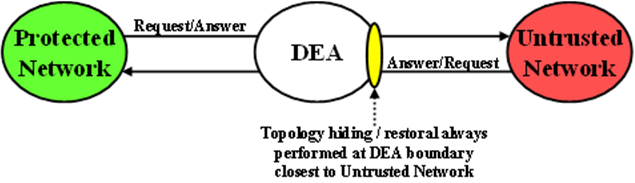
Diameter Edge Agent (DEA) Topology Hiding procedures are always invoked on the interface closest to an Untrusted Network, as illustrated in Figure 1.
Topology Hiding Trigger Points
- Information hiding Trigger Point: A TH Trigger Point that, when invoked, attempts to hide any topology related-information within a Diameter message that is being sent to an Untrusted Network. This type of TH Trigger Point is identified by the TH suffix in the Trigger Point name.
- Information restoral Trigger Point: A TH Trigger Point that, when invoked, attempts to restore any topology hidden information within a Diameter message received from an Untrusted Network to its original or actual value. This type of TH Trigger Point is identified by the TR suffix (Topology Restoral) in the Trigger Point name.
For Protected-to-Untrusted Network Diameter transactions, any topology-sensitive information in the Protected-to-Untrusted Network Request message is hidden just prior to forwarding the Request message to a Peer Node that serves as a gateway to the Untrusted Network. (The adjacent Peer Node may be a member of a Untrusted Network or may be connected directly or indirectly to Diameter nodes that are members of an Untrusted Network from the Protected Network's perspective.)
For the purposes of Diameter Routing Function transaction processing, the Trigger Point for evaluating whether topology-related information should be hidden is called Request Topology Hiding (RTH).
When the Diameter Edge Agent (DEA) receives an Answer message associated with a Protected-to-Untrusted Diameter transaction, it must consider whether the Answer message contains any hidden topology-related information that must be restored to its original value. This Trigger Point is called Answer Topology Restoral (ATR).
The high level logical locations of the RTH and ATR TH Trigger Points for Protected-to-Untrusted Network Diameter transactions are shown in Figure 2.
For Untrusted-to-Protected Network Diameter transactions, any topology-hidden information embedded in the Untrusted-to-Protected Network Request message may be a candidate for topology information restoral. The Trigger Point for evaluating whether topology-related information in a Request message should be restored is called Request Topology Restoral (RTR).
When the DEA forwards an Answer message to an Untrusted Network, it must consider whether the Answer message contains any topology-sensitive information about the Protected Network. This Trigger Point is called Answer Topology Hiding (ATH).
The high level logical locations of the RTR and ATH TH Trigger Points for Untrusted-to-Protected Diameter transactions are shown in Figure 3.
- Information hiding Trigger Points - immediately prior to Mediation
- Information restoral Trigger Points: immediately after Mediation
The Diameter Routing Function has the ability to edit messages just prior to forwarding them to Peer Nodes. Any Diameter Routing Function message editing must be performed prior to any TH treatment. For example, a DSR Application, when forwarding a Request message to the Diameter Routing Function, can ask the Diameter Routing Function to replace the Origin-Realm and Origin-Host AVP values with the Realm and FQDN values assigned to the Local Node associated with the egress Diameter Connection just prior to forwarding the message to the Diameter Transport Function. This Origin-Realm/Origin-Host AVP replacement function must be performed before the TH Trigger Point.
Table 1 summaries the topology information hiding and restoral procedures that are supported at each TH Trigger Point.
| Trigger | TH Type | AVP | Information Hiding / Restoral Procedure |
|---|---|---|---|
| RTH | Path | Route-Record | All AVPs containing Protected Network host names are replaced with a single AVP containing a Pseudo Hostname assigned to the Protected Network. |
| Proxy-Host | Each AVP containing Protected Network host names is replaced with a unique AVP Pseudo Hostname. | ||
| HSS | Origin-Host | Replaced the AVP value with the single HSS Pseudo Hostname assigned to the Protected Network | |
| Session-Id | Host portion replaced by the single HSS Pseudo Hostname assigned to the Protected Network. | ||
| MME/SGSN | Origin-Host | Replaced by one of the Pseudo Hostnames assigned to the MME/SGSN. | |
| Session-Id | Host portion of this AVP value replaced by one of the Pseudo Hostnames assigned to the MME/SGSN | ||
| PCRF | Origin-Host | Replace the AVP value with one of the pseudo-host names assigned to the actual PCRF in S9 PCRF TH Configuration Set for S9 messages and for Rx messages if S9 AF/pCSCF TH Configuration Set is not assigned to the Protected network. | |
| Session-Id | Replace the host portion of this AVP with one of the pseudo-host names assigned to the actual AF/pCSCF in S9 PCRF TH Configuration Set for S9 messages and for Rx messages if S9 AF/pCSCF TH Configuration Set is not assigned to the Protected network. | ||
| AF/pCSCF | Origin-Host | Replace the AVP value with one of the pseudo-host names assigned to the actual AF/pCSCF in S9 AF/pCSCF ThH Configuration Set for Rx messages. | |
| Session-Id | Replace the host portion of this AVP with one of the pseudo-host names assigned to the actual AF/pCSCF in S9 AF/pCSCF Th Configuration Set for Rx messages. | ||
| RTR | Path | Route-Record | Message loop detection and rejection if a
Route-Record AVP contains a pseudo-name that is assigned to the
Protected Network that initiated the message.
Note: Message Loop Detection is done at a Loop
Detect point just prior to RTR.
|
| HSS | None; HSS Pseudo Hostname to Actual Hostname restoral is performed by a HSS Address Resolution application like DSR's FABR or RBAR. | N/A | |
| MME/SGSN | Destination-Host | Replace the MME/SGSN Pseudo Hostname with the MME/SGSN's Actual Hostname. | |
| PCRF | Destination-Host | Replace the PCRF pseudo-host name with the PCRF's actual-host name. | |
| Session-Id | Replace the host portion of this AVP with actual PCRF host name. | ||
| AF/pCSCF | Destination-Host | Replace the AF/pCSCF pseudo-host name with the AF/pCSCF actual-host name. | |
| Session-Id | Replace the host portion of this AVP with actual AF/pCSCF host name. | ||
| ATH | Path | Route-Record | All AVPs containing Protected Network host names are replaced with a single AVP containing a Pseudo Hostname assigned to the Protected Network. |
| Error-Reporting-Host | For each AVP containing a Protected Network host name, encrypt the value using the encryption key assigned to the Protected Network. | ||
| HSS | Origin-Host | Replace the HSS host name with the single HSS Pseudo Hostname assigned to the Protected Network. | |
| MME/SGSN | Origin-Host | Replace the MME/SGSN host name with one of the MME/SGSN's Pseudo Hostnames based on content of the User-Name AVP (containing an IMSI). | |
| PCRF | Origin-Host | Replace the AVP value with one of the pseudo-host names assigned to the actual PCRF in S9 PCRF TH Configuration Set for S9 messages and for Rx messages if S9 AF/pCSCF TH Configuration Set is not assigned to the Protected network. | |
| Session-Id | Replace the hostname received in the Request Session-ID AVP which is saved in the PTR. | ||
| AF/pCSCF | Origin-Host | Replace the AVP value with one of the pseudo-host names assigned to the actual AF/pCSCF in S9 AF/pCSCF TH Configuration Set for Rx Messages. | |
| Session-Id | Replace the hostname received in the Request Session-ID AVP which is saved in the PTR. | ||
| ATR | Path | Proxy-Host | Each AVP instance that was hidden in the forwarded in the Request message must be restored to its original value that is stored in the PTR |
| HSS | Session-Id | Restore the HSS's host name received in the Request Session-Id AVP that is stored in the PTR. | |
| MME/SGSN | Session-Id | Restore the HSS's host name received in the Request Session-Id AVP that is stored in the PTR. | |
| PCRF | Session-Id | Restore the PCRF's host name received in the Request Session-Id AVP which is stored in the PTR. | |
| AF/pCSCF | Session-Id | Restore the AF/pCSCF's host name received in the Request Session-Id AVP which is stored in the PTR. |
Message Candidates for Topology Hiding and Restoral
- Is the message that was just received (or about to be sent) a potential Topology Hiding and Restoral candidate?
- If the message is a potential candidate, is this a message between a Protected Network and an Untrusted Network?
To facilitate potential candidates, the Peer Node configuration element called Topology Hiding Status must be set to Enabled on any Peer Node that is associated with at least one Untrusted Network.
- Protected Networks: Defines, for each Protected Network, the Protected Realm Name and an optional reference to a Trusted Network List. The assumption is that all networks are Untrusted to a Protected Network unless they appear in a Trusted Network List that is assigned to that Protected Network. In essence, the Trusted Network List is a white list; any Network Realm Name that is not in that list is an Untrusted Network. If a Protected Network is not assigned a Trusted Network List, then it is assumed that all networks (except itself) are Untrusted.
- Trusted Network List: A list of Trusted Network Realm Names. A Trusted Network List can be assigned to any Protected Network.
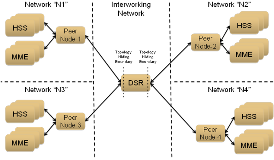
For the sake of discussion, assume that all of the networks are Protected Networks and the Protected Networks and Trusted Network Lists shown in Table 2 and Table 3 are configured:
| Protected Network Name | Protected Network Realm Name | Trusted Network List Name |
|---|---|---|
|
N1 |
n1.com |
Trusted Networks-1 |
|
N2 |
n2.com |
Trusted Networks-2 |
|
N3 |
n3.com |
Trusted Networks-3 |
|
N4 |
n4.com |
Trusted Networks-4 |
| Protected Network Name | Network Realm List |
|---|---|
|
Trusted Networks-1 |
n3.com |
|
Trusted Networks-2 |
n3.com n4.com |
|
Trusted Networks-3 |
n2.com |
|
Trusted Networks-4 |
n1.com n2.com n3.com |
Based on the example Protected Networks and Trusted Network Lists, the trust relationship matrix among the four networks in this example configuration is shown in Table 4.
| Protected Network | Relationship with Peer Network | |||
|---|---|---|---|---|
| N1 | N2 | N3 | N4 | |
|
N1 |
Trusted |
Not Trusted |
Trusted |
Not Trusted |
|
N2 |
Not Trusted |
Trusted |
Trusted |
Trusted |
|
N3 |
Not Trusted |
Trusted |
Trusted |
Not Trusted |
|
N4 |
Trusted |
Trusted |
Trusted |
Trusted |
| Is this network Untrusted by at least one other network? | Yes | Yes | No | Yes |
Based on the Network Trust Relationship Matrix, the Peer Node element settings for the network shown in Table 5 would be used:
| Peer Node | Topology Hiding Status Element Setting |
|---|---|
|
Peer Node-1 |
Enabled |
|
Peer Node-2 |
Enabled |
|
Peer Node-3 |
Disabled |
|
Peer Node-4 |
Enabled |
With the information in Table 5, the TH type-independent criteria for determining whether a message is a potential candidate for Topology Hiding/Restoral are defined in Table 6.
| TH Trigger | Message | Message Path | General Topology Hiding/Restoral Candidate Criteria |
|---|---|---|---|
|
RTH |
Request |
Protected-to-Untrusted |
Egress Peer Node Topology Hiding Status is Enabled, AND Origin-Realm is a Protected Network X, AND Destination-Realm is an Untrusted Network to Protected Network X |
|
RTR |
Request |
Untrusted-to-Protected |
Ingress Peer Node Topology Hiding Status is Enabled, AND Destination-Realm is a Protected Network X, AND Origin-Realm is an Untrusted Network to Protected Network X |
|
ATH |
Answer |
Protected-to-Untrusted |
Egress Peer Node Topology Hiding Status is Enabled, AND Origin-Realm is a Protected Network X, AND Realm of the Diameter Node that originated the transaction is an Untrusted Network to Protected Network X TH Trigger point ATH occurs after the Diameter Routing Function deallocates the PTR for the transaction. Therefore, the Origin-Realm value that was received in the Request message must be stored in the Application-Data stack event just prior to deallocating the PTR in order for the Diameter Routing Function to make an evaluation at ATH of whether the Answer response is being sent to an Untrusted Network. |
|
ATR |
Answer |
Untrusted-to-Protected |
PTR contains one or more indications that topology information restoral is required For Untrusted-to-Protected Answer messages, any information that was hidden in the egress Request is a candidate for restoral regardless of which "Network" sends the Answer message response. Topology information restoral at ATR is always performed regardless of the egress Peer Node's Topology Hiding Status if Topology Hiding was performed on the egress Request message for this Diameter transaction. |
If the TH Trigger Point criteria defined in Table 6 are met, then the Diameter Routing Function must determine which TH types are enabled for the associated Protected Network. Each TH type might have additional criteria that must be met in order to determine whether topology-related information hiding or restoral is required.
The Protected Networks configuration component defines which TH types are enabled for the Protected Network. If a Configuration Set for the TH type is assigned to the Protected Network, then that TH type is enabled for that Protected Network and the rules for that TH type are applied. The Path, S6a/S6d HSS, MME/SGSN, S0 PCRF, and S9 AF/pCSCF TH types are supported. An example Protected Network component for the use case network defined in this section could look like the configuration in Table 7:
| Protected Network Name | Protected Network Realm Name | Trusted Network List Name | Path TH | S6a/S6d HSS TH | MME/SGSN TH | S9 PCRF TH | S9 AF/pCSCF TH |
|---|---|---|---|---|---|---|---|
|
N1 |
n1.com |
Trusted Networks-1 |
Path Config Set-1 |
S6a/S6d HSS Config Set-1 |
MME/SGSN Config Set-1 |
NULL | NULL |
|
N2 |
n2.com |
Trusted Networks-2 |
Path Config Set-2 |
S6a/S6d HSS Config Set-1 |
MME/SGSN Config Set-1 |
NULL | NULL |
|
N3 |
n3.com |
Trusted Networks-3 |
Path Config Set-3 |
NULL |
NULL |
S9 PCRF Config Set-1 | S9 AF/pCSCF onfig Set-1 |
|
N4 |
n4.com |
Trusted Networks-4 |
Path Config Set-4 |
NULL |
NULL |
S9 PCRF Config Set-2 | S9 AF/pCSCF onfig Set-2 |
In the example, if a message associated with Protected Network N3 is a candidate for topology hiding/restoral, then the Diameter Routing Function will invoke only the Path Topology Hiding Configuration Set rules for that message.
The TH type-specific Hiding/Restoral rules are defined in Topology Hiding Types.
Supported AVPs
- Pseudo Hostname Replacement: Actual Hostnames are replaced with Pseudo Hostnames.
- Encryption: AVP value is encrypted
| Diameter Applications | AVP Name | Information Hiding Method | |
|---|---|---|---|
| Pseudo-Host Name Replacement | Encryption | ||
| S6a, S6d, S9, Rx | Session-Id | X | |
| S6a, S6d, S9, Rx | Origin-Host | X | |
| Any | Route-Record | X | |
| Any | Proxy-Host | X | |
| Any | Error-Reporting-Host | X | |
Encryption
Any encryption required by Topology Hiding uses Advanced Encryption Standard (AES), which is a specification for the encryption of electronic data established by the U.S. National Institute of Standards and Technology (NIST) in 2001. AES has been adopted by the U.S. government and is now used worldwide. It supersedes the Data Encryption Standard (DES) that was published in 1977.
AES is an iterative, symmetric-key block cipher that can use keys of 128, 192, and 256 bits (with 256 being the hardest to crack), and encrypts and decrypts data in blocks of 128 bits (16 bytes). Unlike public-key ciphers that use a pair of keys, symmetric-key ciphers use the same key to encrypt and decrypt data. Encrypted data returned by block ciphers have the same number of bits that the input data had. Iterative ciphers use a loop structure that repeatedly performs permutations and substitutions of the input data. All three key lengths are sufficient to protect classified information up to the SECRET level.
AES must be used in conjunction with a FIPS (Federal Information Processing Standard) approved or NIST recommended mode of operation. The mode specifies how data will be encrypted (cryptographically protected) and decrypted (returned to original form). Diameter Topology Hiding supports AES-Cipher BlockChaining (CBC) mode and a 128-bit key size.
Assumptions
- In order to detect message looping for Request messages containing a Route-Record Pseudo Hostname, all Diameter Edge Agents in the service provider's network must have the same Topology Hiding configuration.
- A message loop for Request messages containing a Route-Record Pseudo Hostname may not be detected for messages returned to any Diameter Edge Agent from any network that is trusted by the Protected Network that initiated the Diameter transaction.