If an integrated riveted component of a Pilot chassis is damaged, the chassis must be replaced as soon as possible.
- Prerequisites:
Ensure that you have a Phillips Number 2 screwdriver with at least a 4-inch shaft.
Contact Oracle Customer Support. Oracle creates a replacement chassis with the appropriate system serial number and identifying information.
Before handling a component, touch a grounded surface to discharge any static electricity.
Attach an electrostatic discharge (ESD) wrist strap to your wrist, and stand on an ESD mat while replacing components.
Ensure that there is a workbench available to place the Pilot chassis once it is removed from the rack for servicing.
Fail over the Pilot before replacing the component using Guided Maintenance.
Note: The Pilot must be failed over to prevent data loss or data corruption during the component replacement process.
Each Oracle Flash Storage System has two Pilots installed in the rack. The Pilot chassis is a field replaceable unit (FRU). Replacing a Pilot chassis requires you to bring the failed Pilot offline and fail over operations to the standby Pilot using Guided Maintenance.
- Remove the Pilot from the rack.Removing the Pilot from the rack includes the following tasks:
Identify the failed component for replacement
Power off the Pilot.
Disconnect the Pilot cabling and the cable management arm (CMA).
Slide the Pilot into service position.
Remove the Pilot chassis from the rack.
- Locate the failed
component by checking the status of the component LEDs. You can also use Oracle FS System Manager (GUI) to view the status. From the GUI, navigate to and then select the chassis type of interest.
- From the GUI, prepare the system for component replacement.
- Notify affected users that the Pilot will be powered off.
- Ensure that the host of the Pilot on which the replacement procedure must be performed is powered off.
- Disconnect
all power and data cables from the Pilot.These include:
Ethernet cables connected to the network ports
Rollover cable connected to the serial port
Power cables connected to the power supplies of the Pilot
Note: Oracle Customer Support recommends labeling all cables connected to the Pilot so that they can be re-connected accurately to the Pilot after the replacement procedure is complete.Important! Ensure that the Pilot is offline before removing the power cords.CautionWhen the Pilot is offline, power is still directed to the power supply fans in the Pilot. To completely power off the Pilot, you must disconnect the power cords from the back of the power supplies. - Disconnect
the cable management arm (CMA) by pulling the release tabs on the
left and right side of the CMA.Note: Do not disconnect the cables attached to the CMA.Figure 1 CMA release tabs
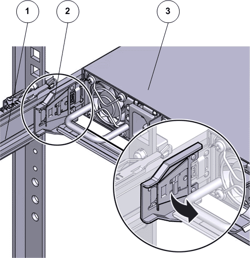
- Legend
1 CMA 2 Release tab to disconnect the CMA 3 Pilot
Important! Before sliding out the Pilot, ensure that the cables do not interfere with the movement of the Pilot. Although the cable management arm (CMA) is hinged to accommodate extending the Pilot, ensure that all cables and cords are capable of being extended. - Slide the Pilot chassis fully forward
until the slide rails lock into position.Figure 2 Pilot position during component replacement
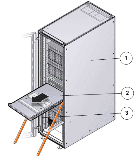
- Legend
1 Rack 2 Pilot chassis 3 Pilot rails
- When Guided
Maintenance prompts you to remove the component, pull the flip handles
at front of the Pilot and start sliding the Pilot out of the rack. CautionDeploy any rack anti-tilt mechanism before releasing the release buttons and extending the Pilot.Figure 3 Pilot slide lockout release tabs
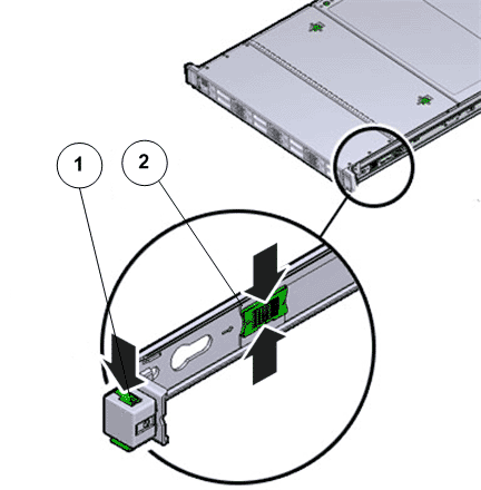
- Legend
1 Slide rail lock 2 Slide lockout release tab
Note: The slide-rail locks are located behind the flip-down handles on the front of the Pilot chassis. The slide-rail locks are released when the flip-down handles are pulled down. The slide lockout release tab must be released to push the Pilot chassis back into the rack. - From the
front of the Pilot, pull the slide-rail
release tabs toward the front of the Pilot and pull the Pilot out of the rack until
it is free of the rack rails.Note: A slide-rail release tab is located on each slide-rail. To pull the slide-rail release tab, place your finger in the center of the tab, not on the end, and apply pressure as you pull the tab toward the front of the Pilot.
- With the
help of a partner or a mechanical lift, place the Pilot on an antistatic surface
or ESD qualified mat or workbench. CautionDeploy any rack anti-tilt mechanisms before removing or installing the Pilot into the rack.CautionThe Pilot weighs approximately 39.9 pounds (18.1 kilograms). Two people are required to dismount and carry the chassis.CautionDo not use the power supply handles to lift the chassis. Using the power supply handles to lift the chassis can damage the power supplies and disrupt electrical power to the Pilot.
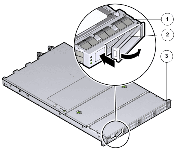
- Press the two
fan door release tabs simultaneously forward and swing the Pilot fan door to the open
position.Note: Servicing the Pilot fan modules and other components located in the front of the Pilot, such as the front indication module (FIM) and the disk backplanes, require that the fan door be opened. It is also easier to remove the Pilot’s top cover if you open the fan door first.Figure 4 Pilot with fan door open
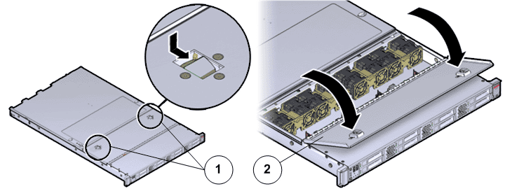
- Legend
1 Fan door release tabs 2 Pilot fan door in open position
- Press down
on the push button on the Pilot top cover to release
the top cover and use the recessed areas to slide the top cover toward
the back of the Pilot about 0.5 inches (12.7
mm).CautionBefore removing the top cover of the Pilot, power off the Pilot using Guided Maintenance. Removing the Pilot top cover before powering off the Pilot might cause damage to the software image on the Pilot.Tip: Slide out the Pilot top cover by pressing down on the grooves located on both sides of the cover.Figure 5 Pilot top cover removal
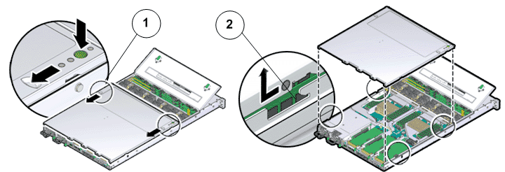
- Legend
1 Push button to release top cover 2 Grooves to slide out top cover
- Lift the cover off the Pilot chassis and set it aside.
- Remove the necessary components on the Pilot following the procedures outlined below.Note: All components that are removed from the Pilot must be placed on an antistatic surface or ESD qualified mat.
- From the back of the Pilot, remove the velcro that holds the power cord from the failed power supply. Note: You might need to swing the cable management arm (CMA) out of the way to access the power supplies. If the CMA is still in the way, extend the Pilot approximately 20 cm (8 inches) out of the front of the rack.Note: The fans of a failed power supply may still be spinning when the system is powered on. You can remove a power supply while the fans are still spinning.
- Disconnect the power cord from the failed power supply.
- While holding the power supply handle with one hand, use the other hand to push the power supply latch to the left.Figure 6 Power supply removal
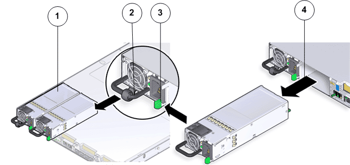
- Legend
1 Power supplies (PS0 and PS1) 2 Power supply handle 3 Power supply latch 4 Power supply compartment
- Pull the power supply out of the chassis and place the power supply on an antistatic mat.CautionWhenever you remove a power supply, you should replace it with another power supply; otherwise, the Pilot might overheat due to improper airflow.
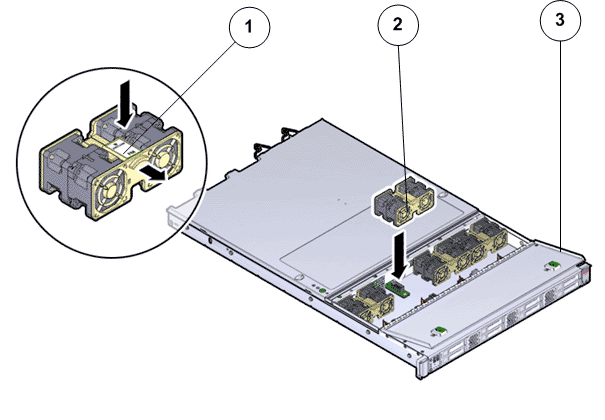
- Using your thumb and forefinger on both sides of the fan module tab, gently lift the fan module from the fan compartment. Figure 7 Pilot fan module removal
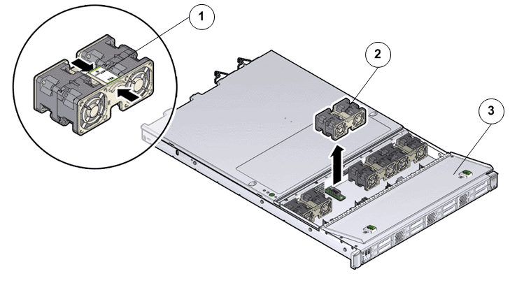
- Legend
1 Fan module tab 2 Fan modules 3 Fan door
Note: When removing a fan module, do not rock it back and forth. Rocking the fan module can cause damage to the motherboard connectors. - Set the fan module aside on an antistatic mat.Note: When replacing a fan module, do not service any other components unless the system is shut down and the power cords are removed.
- Lift the fan compartment straight up and out of the Pilot chassis.Note: All fan modules must be removed from the fan compartment before removing the fan compartment.
- Set the component aside.
- Remove the DIMM by pressing down on the tabs on both sides of the DIMM to unlock it from the slot.Figure 8 Pilot DIMM removal
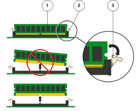
- Legend
1 DIMM 2 DIMM slot 3 DIMM tab
Note: While inserting or removing DIMMs, ensure that there is no interference with the cables. Pulling or pressing down on the cables might cause damage to the cables during the replacement procedure. - Lift out the faulted DIMM and set aside on an antistatic mat.Note: Visually inspect the DIMM slots, and the DIMM, for physical damage by checking for cracked or broken plastic in the slot.Note: Sometimes DIMMs might fault because of dust or improper alignment or damaged slots. Use only compressed air to dust DIMMs.
- Tip: A portion of the air duct over CPU-1 must be removed to access CPU-1 and Heat sink-1.Loosen the four Phillips screws on the four sides of the heat sink in a diagonal pattern using a Phillips Number 2 screwdriver.
The four Phillips screws on the four sides of the heat sink secure the heat sink to the Pilot chassis.
Figure 9 Loosen four screws to remove heat sink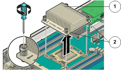
- Legend
1 Heat sink 2 Phillips screws that secure the heat sink
- Lift up the
heat sink and set aside the failed heat sink on an antistatic mat.Note: Visually inspect the failed heat sink to verify if the thermal grease has dried out. After cleaning the heat sink with an alcohol pad, apply thermal grease to the heat sink, if necessary.
- Press gently on the lever at the side of the CPU socket to disengage the CPU socket.Figure 10 CPU socket disengaged
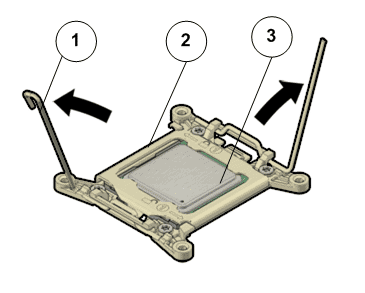
- Legend
1 CPU socket lever 2 CPU socket 3 CPU
This exposes the CPU inside the CPU socket.
CautionThe correct CPU removal or replacement tool must be used to remove and replace a CPU. Otherwise, the CPU or the CPU socket might be damaged. The correct CPU removal/replacement tool is included in the box with the replacement CPU. Additionally, both removal or replacement tools ship with replacement motherboards.The model for the CPUs in the Oracle FS System Pilot is E5-2609 V2 (4 core processor) and requires a CPU removal tool that is color coded green.Figure 11 CPU removal tool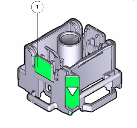
- Legend
1 CPU removal tool color coded green
- Gently disengage the CPU pins on the underside to lift up the CPU from the CPU socket and set aside the failed CPU on an antistatic mat.Figure 12 CPU removal
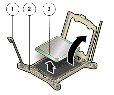
- Legend
1 CPU socket lever 2 CPU socket 3 CPU
- Remove the battery by placing your finger or a pointed tool like a screwdriver under the battery on the side nearest to the back of the Pilot and gently lifting the battery out of the retainer.Figure 13 Battery removal
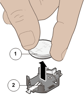
- Legend
1 Pilot battery 2 Battery socket
- Place the battery on an antistatic mat.Note: Replacing a battery usually resets the CMOS settings to a default value. Export the BIOS settings to an XML file from the ILOM prior to battery replacement and then import the settings in the BIOS when the battery replacement is completed.
- Press on the release tab of the riser to release the riser from the Pilot motherboard.
- Carefully pull up the release tab on the riser to release the filler panel or HBA card (if any) and pull the riser straight up.Figure 14 Riser board assembly removal
- Legend
1 Release tab on the riser 2 Riser 3 HBA 4 Motherboard
Note: You do not need to remove the SAS host bus adapters (HBAs) or HBA cables from the riser unless the riser has failed and the HBA or cables must be transferred to the replacement riser. Remove any HBA cables or HBAs that are on the failed riser assemblies using the appropriate procedure. Make a note of the riser slot in which the HBAs are installed and the SAS cables that are connected to the HBAs. - Disconnect the SAS cable bundle that connects the SAS HBA and the Pilot disk backplane and set aside.Figure 15 Disconnect SAS cable bundle
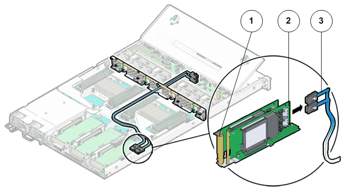
- Legend
1 Riser 2 HBA 3 SAS cable bundle
- Remove any HBA cards (usually the SAS card) that are inserted into the PCI-express (PCI-e) slots of the riser and place the riser and the HBA cards on an antistatic mat. Note: Retain the HBA cards because they will be placed inside the replacement riser board assembly.
- Identify the riser in which the failed SAS HBA is located.Note: There are three riser board assemblies inside the Pilot chassis.
- On the Pilot with the failed SAS HDD, press the drive carrier latch to disengage the SAS HDD.Figure 16 SAS HDD removal
- Legend
1 SAS HDD 2 Drive carrier latch 3 Pilot front
Important! The drive carrier latch is not an ejector. Do not bend the latch too far to the right. Bending the latch can damage the latch. - Grasp the drive carrier latch and pull the SAS HDD out of the Pilot drive compartment.
- Place the failed SAS HDD on an antistatic mat.
- Pull out all the storage drives or filler panels from the drive compartment far enough to disengage it from the disk backplane.Note: It is not necessary to completely remove the storage drives from the Pilot. However, you must pull them out far enough to disengage them from the disk backplane. If you remove the storage drives from the Pilot, make a note of their locations so that you can reinstall the storage drives in the same locations.
- If replacing both disk backplane boards, disconnect the SAS cable bundle starting with the top board of the disk backplane.
If you are going to remove and replace both disk backplane boards, make a note of which cables connect to the top disk backplane and which cables connect to the bottom disk backplane. Do this before disconnecting any backplane cables.
Figure 17 Disk backplane cables disconnected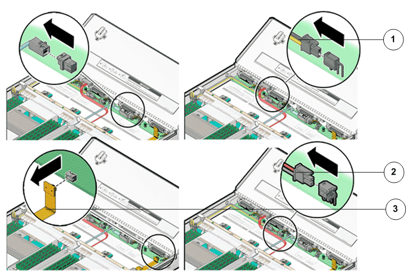
- Legend
1 Disk backplane power cable 2 LED cable 3 SAS cable bundle
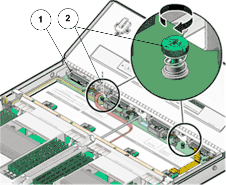
- Disconnect the disk backplane LED cable (1U system controller cable) and the disk backplane power cord from the disk backplane.
- Using your thumb and fingers, loosen the two captive thumb screws that secure the disk backplane to the Pilot chassis.Figure 18 Captive thumb screws to remove disk backplane
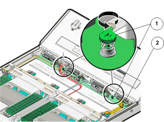
- Legend
1 Captive thumb screws 2 Disk backplane
- Slide the disk backplane forward toward the front of the Pilot to release it from the three standoffs and lift it out of the chassis.Figure 19 Pilot disk backplane removal
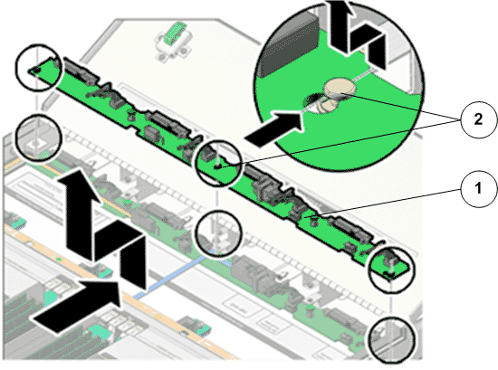
- Legend
1 Disk backplane 2 Standoffs
- Place the disk backplane on an antistatic mat.If replacing both disk backplane boards, repeat the steps for the second board.
- Insert the necessary components on the Pilot following the procedures outlined below.Some components had to be removed from the Pilot as a prerequisite while replacing the failed component. These components must be reinstalled after completing the replacement.
- Unpack the
component from its shipping carton.Note: Place the component on an antistatic mat if it must be set aside for any reason.
- Lower the disk backplane into the Pilot and position it to engage the three standoffs.Figure 20 Pilot disk backplane positioned over standoffs
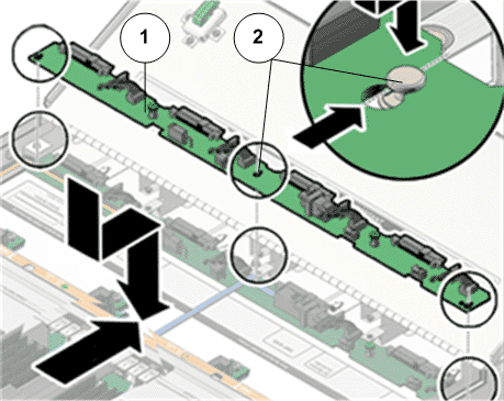
- Legend
1 Disk backplane 2 Standoffs
Note: If replacing two disk backplane boards, start by installing the bottom disk backplane board. - Using just your thumb and fingers, tighten the two captive thumb screws to secure the disk backplane to the Pilot chassis.Figure 21 Captive thumb screws to secure disk backplane
- Legend
1 Disk backplane 2 Captive thumb screws
- Reconnect the disk backplane LED cable (1U system controller cable) and the disk backplane power cord to the disk backplane.
- Reconnect the SAS cable bundle to the disk backplane.Figure 22 Disk backplane cables connected
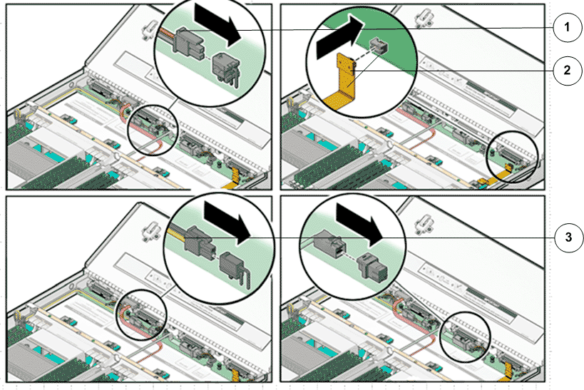
- Legend
1 SAS cable bundle 2 LED cable 3 Disk backplane power cable
Note: After replacing the disk backplane, you must manually program the product serial number (PSN) into the replacement disk backplane. Programming the PSN on the disk backplane is important for service entitlement. - Reinstall all of the storage drives into the drive compartment.
- Unpack the
component from its shipping carton.Note: Place the component on an antistatic mat if it must be set aside for any reason.
- Insert and slide the replacement SAS HDD into the drive slot until the SAS HDD is fully seated into the slot.Figure 23 SAS HDD insertion
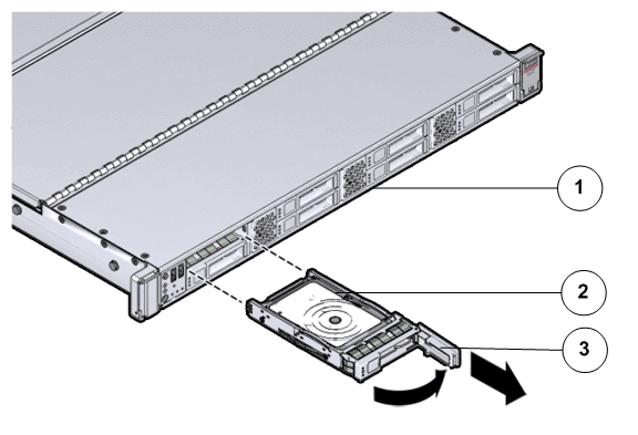
- Legend
1 Pilot front 2 SAS HDD 3 Drive carrier latch
Note: Replacing the failed SAS HDD with a blank SAS HDD into the Pilot drive slot will not boot up the Pilot. Use Guided Maintenance (GM) to re-install the operating system on the Pilot SAS HDD and enable the Pilot to re-join the network automatically without any special configuration. - Close the drive carrier latch to lock the SAS HDD in place.Note: Do not force open the drive carrier latch. You can damage the drive carrier latch if you apply too much force.
- Re-configure the SAS HDD by creating a Pilot image on the SAS HDD.
- Unpack the
component from its shipping carton.Note: Place the component on an antistatic mat if it must be set aside for any reason.
- Orient the SAS HBA so that the brackets of the HBA align with the alignment pin in the PCIe slot of the riser.Figure 24 SAS HBA insertion into the riser
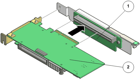
- Legend
1 Riser board 2 SAS HBA
Important! Hold the SAS HBA by the edges. Do not touch the metal contacts on the bottom of the card. - Push the connectors on the edge of the SAS HBA into the PCIe slot by pushing firmly to seat the card.
- Apply firm pressure on each end of the SAS HBA alternately until it clicks into place in the riser socket.CautionSupport the SAS HBA and the riser as necessary to prevent excessive flexure. Otherwise, the SAS HBA or the riser card might break.
- Insert the riser into the black slot on the Pilot motherboard and slide the release tab backward to secure the riser in position.
- Unpack the
component from its shipping carton.Note: Place the component on an antistatic mat if it must be set aside for any reason.
- Insert the HBA cards that were placed aside and insert them in the same PCIe slots as before within the replacement riser.
- Reconnect the SAS cable bundle into the HBA inside the riser.
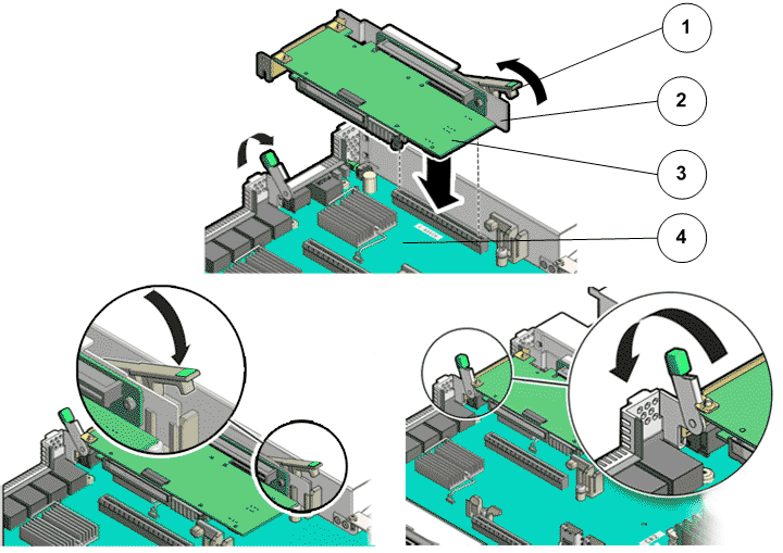
- Insert the riser into the black slot on the Pilot motherboard and slide the release tab backward to secure the riser in position. Figure 25 Pilot riser insertion
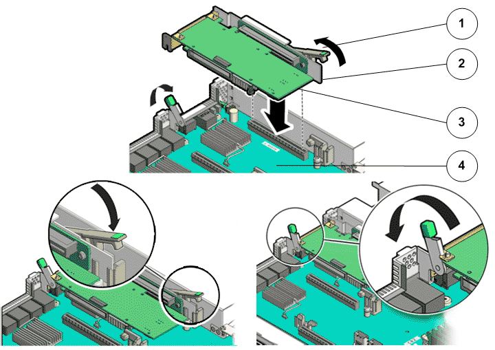
- Legend
1 Release tab 2 Riser 3 HBA 4 Pilot motherboard
- Insert the filler panels, if any, inside the riser.
- Unpack the
component from its shipping carton.Note: Place the component on an antistatic mat if it must be set aside for any reason.
- Press the replacement battery into the battery retainer with the positive side (+) facing upwards.Figure 26 Battery insertion
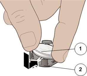
- Legend
1 Pilot battery 2 Battery socket
If the Pilot is configured to synchronize with a network time server using the Network Time Protocol (NTP), the Oracle ILOM clock is reset as soon as the Pilot is powered on and connected to the network. Otherwise, proceed to the next step.
- If the Pilot is not configured to use NTP, reset the Oracle ILOM clock using the web interface. You can also reprogram the BIOS Setup utility to reprogram the host clock.
- Unpack the
component from its shipping carton.Note: Place the component on an antistatic mat if it must be set aside for any reason.
- Gently align the pins on the underside of the CPU to the CPU socket and push down to secure the CPU in the socket.Figure 27 CPU insertion
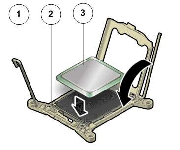
- Legend
1 CPU socket lever 2 CPU socket 3 CPU
- Push down on the lever of the CPU socket to secure the CPU inside.
- Secure
the heat sink over the CPU to the Pilot motherboard by inserting
the four screws on the four sides of the heat sink and tightening
them using a Phillips Number 2 screwdriver.Tip: Ensure that you have thermal grease and syringe available to clean the CPU and heat sink.Figure 28 Heat sink insertion
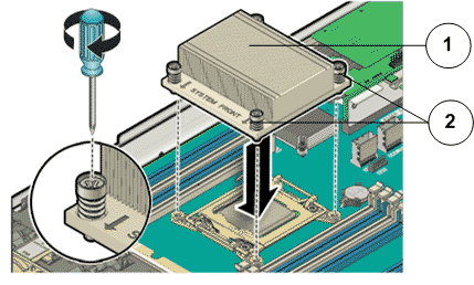
- Legend
1 Heat sink 2 Phillips screws that secure the heat sink
Important! Ensure that the heat sink and the screws are aligned so that the airflow marker on the heat sink faces the back of the Pilot and the system front marker on the heat sink faces the front of the Pilot. Also, ensure that the screws on opposite ends of the heat sink are tightened first. A slight force must be applied to push down the screwdriver while tightening the screws to overcome the tension generated.Note: Install the chassis mid-wall and ensure that the cables are running through the opening in the center of the mid-wall. Position the mid-wall with the cables in front of the motherboard so that it engages the mushroom-shaped standoffs that are located on the chassis sidewall (one for each side of the mid-wall). - Unpack the
component from its shipping carton.Note: Place the component on an antistatic mat if it must be set aside for any reason.
- Press the DIMM fully into the DIMM slot and ensure that the tabs on both sides of the DIMM are locked.Important! Ensure that the notch in the DIMM lines up with the key in the slot. Press down on the DIMM equally across the board, placing your thumbs on opposite ends of the DIMM module to insert it into the slot.Note: Replace only one DIMM at a time to make sure that they are inserted into the correct slots. Attempting to insert multiple DIMMs into the slots might damage the DIMMs due to excessive flexure.Note: Never leave a DIMM slot unpopulated. Insert filler panels into empty DIMM slots to ensure proper air flow inside the Pilot.
- Move any loose cables so that they are against the Pilot chassis walls.
- Align the fan compartment to where it installs into the Pilot chassis.
- Slowly lower the fan compartment into the Pilot chassis, gently working the cables into the gaps between the fan compartment and the chassis walls.
- Verify that the fan compartment is properly seated, no cables are pinched, and the top surfaces of the fan compartment are flush with the Pilot chassis.
- Unpack the
component from its shipping carton.Note: Place the component on an antistatic mat if it must be set aside for any reason.
- Grasp the fan module tabs and press the fan down firmly into the fan module compartment. Figure 29 Fan module insertion
- Legend
1 Fan module tab 2 Fan modules 3 Fan door
Note: Apply firm pressure to fully seat the fan module into the fan compartment. The fan modules are notched to ensure that they are installed in the correct orientation. - Press down on the fan module and apply firm pressure to fully seat the fan module.
- Move any loose cables so that they are against the Pilot chassis walls.
- Align the fan compartment to where it installs into the Pilot chassis.
- Slowly lower the fan compartment into the Pilot chassis, gently working the cables into the gaps between the fan compartment and the chassis walls.
- Verify that the fan compartment is properly seated, no cables are pinched, and the top surfaces of the fan compartment are flush with the Pilot chassis.
- Place the top cover of the Pilot onto the chassis.Tip: Place the top cover down so that it hangs over the back of the Pilot by about 13 mm (0.5 inches) [1] and the side latches align with the slots in the sides of the Pilot chassis.Note: There are three latching tabs on the sides of the Pilot top cover, two on the right side and one on the left side when viewing the Pilot from the front. There is also a latch on the underside of the top cover in the front left corner near the release button.
- Check both sides of the Pilot chassis to ensure that the four corners of the top cover are fully down and flush with the chassis.Note: If the cover corners are not flush with the Pilot chassis, slide the cover towards the back of the chassis until you can position the cover correctly.Note: If the top cover is not correctly positioned before attempting to slide the cover forward, the internal latch that is on the underside of the cover might be damaged.
- Gently slide the top cover along the grooves of the Pilot by pressing down on either side of the top cover until it locks into place and you hear an audible click.Figure 30 Pilot top cover installed
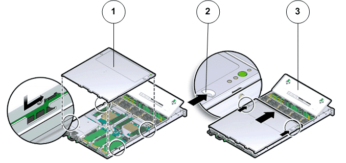
- Legend
1 Top cover 2 Grooves to slide the top cover 3 Fan door
- Close the Pilot fan door by pressing the two release tabs on both sides of the fan door until it locks into place.
- Inserting the Pilot onto the rack includes
the following tasks:
Re-connect the Pilot cabling and the cable management arm (CMA).
Connect the power cords onto the Pilot.
Update the Pilot BIOS.
Install the Top Cover
Slide the Pilot into rack position.
Push power button on the Pilot.
Verify the Pilot component status.
- With the help of a partner or a mechanical lift, raise the Pilot so that the back ends of the mounting brackets are aligned with the slide-rail assemblies that are mounted in the rack.Figure 31 Lift Pilot chassis onto rack
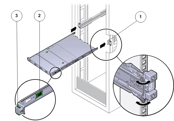
- Legend
1 Inserting mounting brackets into slide-rails 2 Slide-rail release button 3 Slide-rail lock
CautionDeploy any rack anti-tilt mechanisms before installing the Pilot into the rack.CautionThe Pilot weighs approximately 18.1 kg (39.9 lb). Two people are required to carry the chassis and install it into the rack.CautionDo not use the power supply handles to lift the chassis. Using the power supply handles to lift the chassis can damage the power supplies and disrupt electrical power to the Pilot. - Insert the mounting brackets into the slide-rails, then push the Pilot into the rack until the mounting brackets encounter the slide-rail stops at approximately 12 inches (30 cm).The Pilot is now in the extended maintenance position.
- Simultaneously pull and hold the two release tabs, one on each side of the Pilot, toward the front of the Pilot while you push the Pilot into the rack.Figure 32 Location of the Pilot release tabs
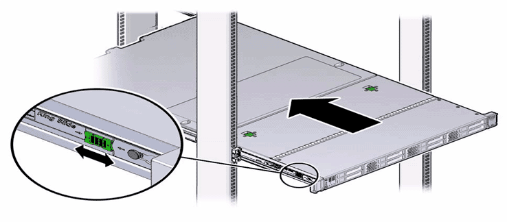 Note: As you push the Pilot into the rack, verify that the cable management arm (CMA) retracts without binding.Note: To pull the Pilot release tab, place your finger in the center of the tab, not on the end, and apply pressure as you pull the tab toward the front of the Pilot.
 - Continue pushing the Pilot into the rack until the slide-rail locks on the front of the Pilot engage the slide-rail assemblies.Note: The Pilot locks into the rack position with an audible click.
- Reconnect the following cables that had been disconnected from the Pilot.
Ethernet cables connected to the network ports
Rollover cable connected to the serial port
Note: If the cable management arm (CMA) is in the way, extend the Pilot approximately 13 cm (5 inches) out of the front of the rack. Once the cables are connected to the ports, the Pilot can be pushed back into the rack position. - Reconnect the power cords to the power supplies and secure them with the velcro straps.
- If necessary, reinstall the cables into the cable management arm (CMA) and secure them with cable straps.
- Reconnect the CMA to the Pilot chassis by reattaching the release tabs on both sides of the CMA.
- Reconnect the
power cords to the Pilot. Note: After the power cords are connected, the green SP LED and the OK LED both start to blink.Note: Do not turn on the power to the Pilot host immediately. The power on the Pilot host is turned on only after updating the Pilot BIOS. Turning on the power to the Pilot host early can prevent the Pilot from booting after the Pilot BIOS is updated.
- From Guided
Maintenance, verify that the status is Normal. You can also verify the status by navigating to and then selecting a chassis. The Overview page for the selected chassis lists the status of each component.Note: The Controller status will be visible several minutes after being powered on.
- Review the status of the LEDs to confirm a status of Normal.
Remove the Pilot from the rack
Identify the Pilot chassis for replacement
Power off the Pilot
Disconnect Pilot cabling and CMA
Slide the Pilot into service position
Remove the Pilot chassis from the rack
Open Pilot fan door
Open Pilot top cover
Remove all components from the failed Pilot
Remove the Pilot power supplies
Remove the Pilot fan modules
Remove the Pilot fan compartment
Remove the Pilot DIMMs
Remove the Pilot heat sink
Remove the Pilot CPUs
Remove the Pilot battery
Remove the Pilot riser
Remove the Pilot SAS HBA
Remove the Pilot SAS HDD
Remove the Pilot disk backplane
Insert all components into the replacement Pilot
Insert the Pilot disk backplane
Insert the Pilot SAS HDD
Insert the Pilot SAS HBA
Insert the Pilot riser
Insert the Pilot battery
Insert the Pilot CPU
Insert the Pilot heat sink
Insert the Pilot DIMMs
Insert the Pilot fan compartment
Insert the Pilot fan modules
Insert the Pilot power supplies
Close Pilot top cover
Close Pilot fan door
Install the Pilot onto the rack
Install the Pilot chassis onto the rack
Slide the Pilot into rack position
Reconnect Pilot cabling and CMA
Power on the Pilot
Verify the Pilot component status