If a fan module fails, the Pilot internal temperature rises quickly. If the temperature exceeds normal thresholds, the system issues critical alerts. Replace fan modules as soon as possible to prevent high-temperature buildup.
- Prerequisites:
Ensure that you have a Phillips Number 2 screwdriver with at least a 4-inch shaft.
Before handling a component, touch a grounded surface to discharge any static electricity.
Attach an electrostatic discharge (ESD) wrist strap to your wrist, and stand on an ESD mat while replacing components.
If you need to replace multiple fan module, replace only one fan module at a time and within five minutes.
Initiate Guided Maintenance only when you are able to replace the fan module immediately.
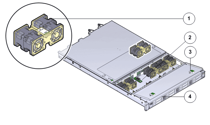
- Legend
1 Fan module 2 Fan compartment 3 Fan door 4 Pilot
- Locate the failed
component by checking the status of the component LEDs. You can also use Oracle FS System Manager (GUI) to view the status. From the GUI, navigate to and then select the chassis type of interest.
- From the GUI, prepare the system for component replacement.
- Slide the Pilot chassis fully forward
until the slide rails lock into position.Figure 2 Pilot position during component replacement
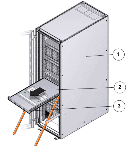
- Legend
1 Rack 2 Pilot chassis 3 Pilot rails
- When Guided
Maintenance prompts you to remove the component, pull the flip handles
at front of the Pilot and start sliding the Pilot out of the rack. CautionDeploy any rack anti-tilt mechanism before releasing the release buttons and extending the Pilot.Figure 3 Pilot slide lockout release tabs
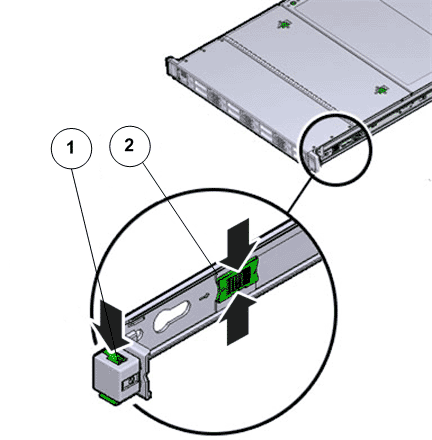
- Legend
1 Slide rail lock 2 Slide lockout release tab
Note: The slide-rail locks are located behind the flip-down handles on the front of the Pilot chassis. The slide-rail locks are released when the flip-down handles are pulled down. The slide lockout release tab must be released to push the Pilot chassis back into the rack. - Press the two
fan door release tabs simultaneously forward and swing the Pilot fan door to the open
position.Note: Servicing the Pilot fan modules and other components located in the front of the Pilot, such as the front indication module (FIM) and the disk backplanes, require that the fan door be opened. It is also easier to remove the Pilot’s top cover if you open the fan door first.Figure 4 Pilot with fan door open
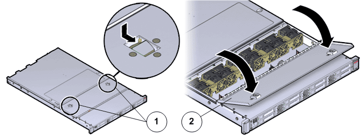
- Legend
1 Fan door release tabs 2 Pilot fan door in open position
- Using your thumb and forefinger on both sides of the fan module tab, gently lift the fan module from the fan compartment. Figure 5 Pilot fan module removal
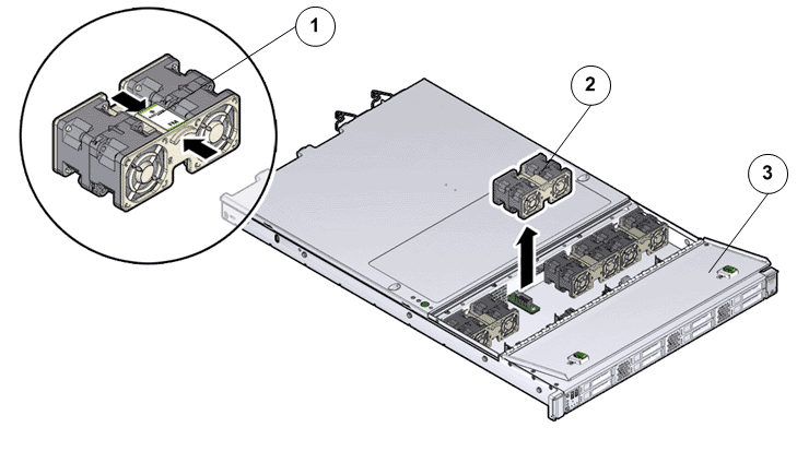
- Legend
1 Fan module tab 2 Fan modules 3 Fan door
Note: When removing a fan module, do not rock it back and forth. Rocking the fan module can cause damage to the motherboard connectors. - Set the fan module aside on an antistatic mat.Note: When replacing a fan module, do not service any other components unless the system is shut down and the power cords are removed.
- Unpack the
component from its shipping carton.Note: Place the component on an antistatic mat if it must be set aside for any reason.
- Grasp the fan module tabs and press the fan down firmly into the fan module compartment. Figure 6 Fan module insertion
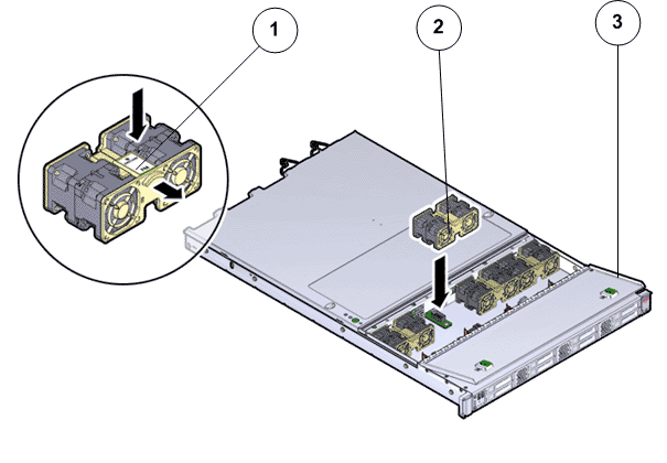
- Legend
1 Fan module tab 2 Fan modules 3 Fan door
Note: Apply firm pressure to fully seat the fan module into the fan compartment. The fan modules are notched to ensure that they are installed in the correct orientation. - Press down on the fan module and apply firm pressure to fully seat the fan module.
- Close the Pilot fan door by pressing the two release tabs on both sides of the fan door until it locks into place.
- Simultaneously pull and hold the two release tabs, one on each side of the Pilot, toward the front of the Pilot while you push the Pilot into the rack.Figure 7 Location of the Pilot release tabs
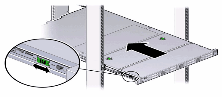 Note: As you push the Pilot into the rack, verify that the cable management arm (CMA) retracts without binding.Note: To pull the Pilot release tab, place your finger in the center of the tab, not on the end, and apply pressure as you pull the tab toward the front of the Pilot.
 - Continue pushing the Pilot into the rack until the slide-rail locks on the front of the Pilot engage the slide-rail assemblies.Note: The Pilot locks into the rack position with an audible click.
- From Guided
Maintenance, verify that the status is Normal. You can also verify the status by navigating to and then selecting a chassis. The Overview page for the selected chassis lists the status of each component.Note: The Controller status will be visible several minutes after being powered on.
- Review the status of the LEDs to confirm a status of Normal.
Identify the Pilot component for replacement
Slide the Pilot into service position
Open Pilot fan door
Remove the failed Pilot fan module
Insert the replacement Pilot fan module
Close Pilot fan door
Slide the Pilot into rack position
Verify the Pilot component status