Riser board assemblies include printed circuit boards and PCIe slots in which HBAs can be inserted based on system type and configuration. A failed riser board assembly can cause read write errors because the HBAs will not be able to function properly. Replace a failed riser board as soon as possible.
- Prerequisites:
Before handling a component, touch a grounded surface to discharge any static electricity.
Attach an electrostatic discharge (ESD) wrist strap to your wrist, and stand on an ESD mat while replacing components.
Ensure that you have a Phillips Number 2 screwdriver with at least a 4-inch shaft.
Fail over the Pilot before replacing the component using Guided Maintenance.
Note: The Pilot must be failed over to prevent data loss or data corruption during the component replacement process.
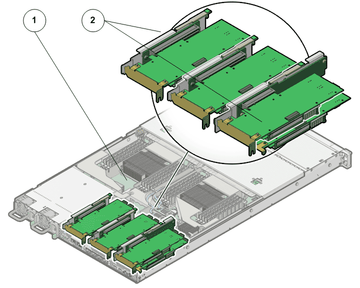
- Legend
1 Pilot motherboard 2 Risers
- Locate the failed
component by checking the status of the component LEDs. You can also use Oracle FS System Manager (GUI) to view the status. From the GUI, navigate to and then select the chassis type of interest.
- From the GUI, prepare the system for component replacement.
- Notify affected users that the Pilot will be powered off.
- Ensure that the host of the Pilot on which the replacement procedure must be performed is powered off.
- Slide the Pilot chassis fully forward
until the slide rails lock into position.Figure 2 Pilot position during component replacement
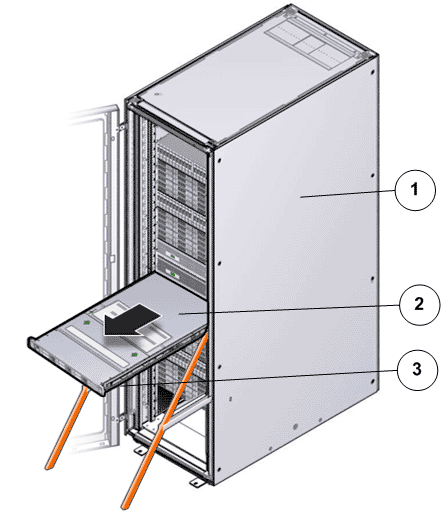
- Legend
1 Rack 2 Pilot chassis 3 Pilot rails
- When Guided
Maintenance prompts you to remove the component, pull the flip handles
at front of the Pilot and start sliding the Pilot out of the rack. CautionDeploy any rack anti-tilt mechanism before releasing the release buttons and extending the Pilot.Figure 3 Pilot slide lockout release tabs
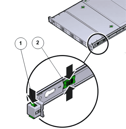
- Legend
1 Slide rail lock 2 Slide lockout release tab
Note: The slide-rail locks are located behind the flip-down handles on the front of the Pilot chassis. The slide-rail locks are released when the flip-down handles are pulled down. The slide lockout release tab must be released to push the Pilot chassis back into the rack. - Press the two
fan door release tabs simultaneously forward and swing the Pilot fan door to the open
position.Note: Servicing the Pilot fan modules and other components located in the front of the Pilot, such as the front indication module (FIM) and the disk backplanes, require that the fan door be opened. It is also easier to remove the Pilot’s top cover if you open the fan door first.Figure 4 Pilot with fan door open
- Legend
1 Fan door release tabs 2 Pilot fan door in open position
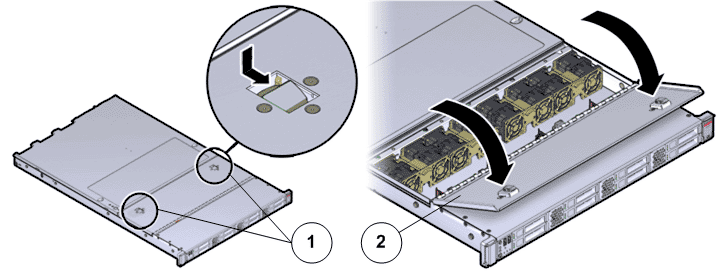
- Press down
on the push button on the Pilot top cover to release
the top cover and use the recessed areas to slide the top cover toward
the back of the Pilot about 0.5 inches (12.7
mm).CautionBefore removing the top cover of the Pilot, power off the Pilot using Guided Maintenance. Removing the Pilot top cover before powering off the Pilot might cause damage to the software image on the Pilot.Tip: Slide out the Pilot top cover by pressing down on the grooves located on both sides of the cover.Figure 5 Pilot top cover removal
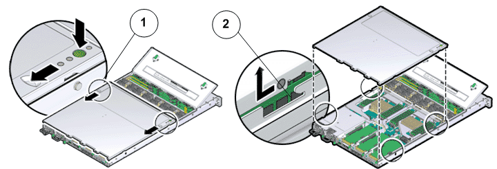
- Legend
1 Push button to release top cover 2 Grooves to slide out top cover
- Lift the cover off the Pilot chassis and set it aside.
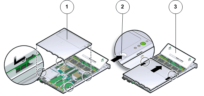
- Press on the release tab of the riser to release the riser from the Pilot motherboard.
- Carefully pull up the release tab on the riser to release the filler panel or HBA card (if any) and pull the riser straight up.Figure 6 Riser board assembly removal
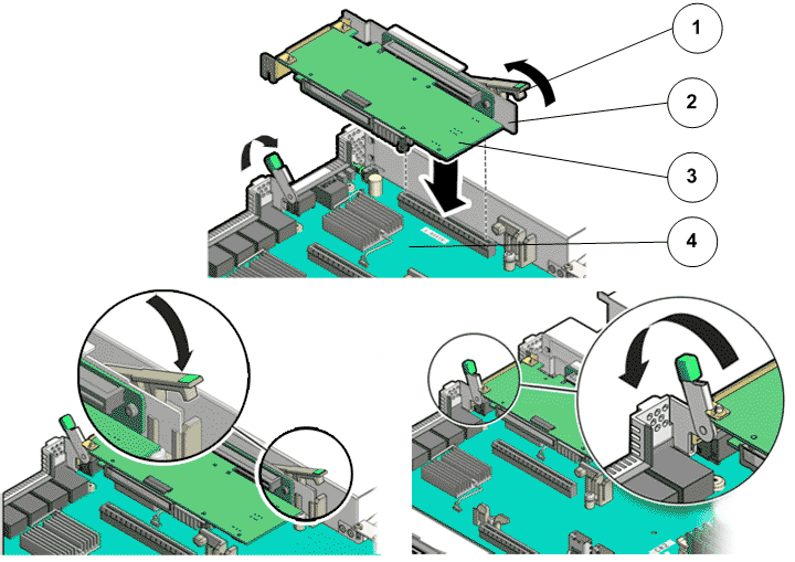
- Legend
1 Release tab on the riser 2 Riser 3 HBA 4 Motherboard
Note: You do not need to remove the SAS host bus adapters (HBAs) or HBA cables from the riser unless the riser has failed and the HBA or cables must be transferred to the replacement riser. Remove any HBA cables or HBAs that are on the failed riser assemblies using the appropriate procedure. Make a note of the riser slot in which the HBAs are installed and the SAS cables that are connected to the HBAs. - Disconnect the SAS cable bundle that connects the SAS HBA and the Pilot disk backplane and set aside.Figure 7 Disconnect SAS cable bundle
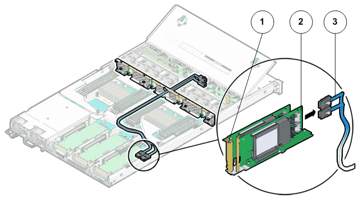
- Legend
1 Riser 2 HBA 3 SAS cable bundle
- Remove any HBA cards (usually the SAS card) that are inserted into the PCI-express (PCI-e) slots of the riser and place the riser and the HBA cards on an antistatic mat. Note: Retain the HBA cards because they will be placed inside the replacement riser board assembly.
- Unpack the
component from its shipping carton.Note: Place the component on an antistatic mat if it must be set aside for any reason.
- Insert the HBA cards that were placed aside and insert them in the same PCIe slots as before within the replacement riser.
- Reconnect the SAS cable bundle into the HBA inside the riser.
- Insert the riser into the black slot on the Pilot motherboard and slide the release tab backward to secure the riser in position. Figure 8 Pilot riser insertion
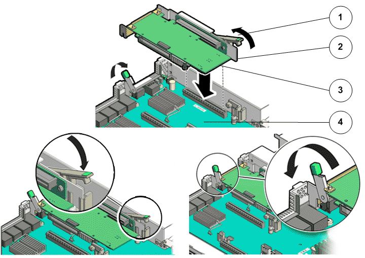
- Legend
1 Release tab 2 Riser 3 HBA 4 Pilot motherboard
- Insert the filler panels, if any, inside the riser.
- Place the top cover of the Pilot onto the chassis.Tip: Place the top cover down so that it hangs over the back of the Pilot by about 13 mm (0.5 inches) [1] and the side latches align with the slots in the sides of the Pilot chassis.Note: There are three latching tabs on the sides of the Pilot top cover, two on the right side and one on the left side when viewing the Pilot from the front. There is also a latch on the underside of the top cover in the front left corner near the release button.
- Check both sides of the Pilot chassis to ensure that the four corners of the top cover are fully down and flush with the chassis.Note: If the cover corners are not flush with the Pilot chassis, slide the cover towards the back of the chassis until you can position the cover correctly.Note: If the top cover is not correctly positioned before attempting to slide the cover forward, the internal latch that is on the underside of the cover might be damaged.
- Gently slide the top cover along the grooves of the Pilot by pressing down on either side of the top cover until it locks into place and you hear an audible click.Figure 9 Pilot top cover installed
- Legend
1 Top cover 2 Grooves to slide the top cover 3 Fan door
- Close the Pilot fan door by pressing the two release tabs on both sides of the fan door until it locks into place.
- Simultaneously pull and hold the two release tabs, one on each side of the Pilot, toward the front of the Pilot while you push the Pilot into the rack.Figure 10 Location of the Pilot release tabs
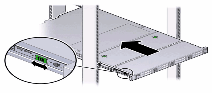 Note: As you push the Pilot into the rack, verify that the cable management arm (CMA) retracts without binding.Note: To pull the Pilot release tab, place your finger in the center of the tab, not on the end, and apply pressure as you pull the tab toward the front of the Pilot.
 - Continue pushing the Pilot into the rack until the slide-rail locks on the front of the Pilot engage the slide-rail assemblies.Note: The Pilot locks into the rack position with an audible click.
- Reconnect the
power cords to the Pilot. Note: After the power cords are connected, the green SP LED and the OK LED both start to blink.Note: Do not turn on the power to the Pilot host immediately. The power on the Pilot host is turned on only after updating the Pilot BIOS. Turning on the power to the Pilot host early can prevent the Pilot from booting after the Pilot BIOS is updated.
- From Guided
Maintenance, verify that the status is Normal. You can also verify the status by navigating to and then selecting a chassis. The Overview page for the selected chassis lists the status of each component.Note: The Controller status will be visible several minutes after being powered on.
- Review the status of the LEDs to confirm a status of Normal.
Identify the Pilot component for replacement
Power off the Pilot
Slide the Pilot into service position
Open Pilot fan door
Open Pilot top cover
Remove the failed Pilot riser
Insert the failed Pilot riser
Close Pilot top cover
Close Pilot fan door
Slide the Pilot into rack position
Power on the Pilot
Verify the Pilot component status