A VLE 1.5 Network Configuration
This appendix describes the VLE network starting with VLE 1.5. Configuration examples illustrate common network scenarios, including:
-
"Example 1: Multiple VTSS-to-VLE Layout without Network Infrastructure"
-
"Example 2: Multiple VTSS-to-VLE Layout with Network Infrastructure"
Network Changes for VLE 1.5
With the introduction of VLE 1.5 and the X4-4 server, quad-port 1 Gb NIC connections are replaced with dual-port 10 Gb NIC connections. The potential network bandwidth for IFF/Replication connections has increased from 16 Gb (=16 x 1 Gb) to at least 40 Gb of optical bandwidth.
Additional 10 Gb copper/RJ-45 ports are also available. This additional bandwidth can simplify network setup. However, additional network infrastructure must be provided by the customer to accommodate this additional bandwidth.
In general, functions are isolated to specific networks on specific ports. This ensures bandwidth for a given function is theoretically available.
Additionally, separate subnets for all interfaces/aggregations is considered a best practice since a link failure could down other VLE ports on the same subnet.
Table A-1 shows the position and function for each of the VLE 1.5 ports in the X4-4 server.
For comparison, Table A-2 shows the same information for versions prior to VLE 1.5.
-
"Cu" indicates Copper/RJ45.
-
"O" indicates Optical.
-
"O or Cu" indicates either; Optical is the default and Cu is 1 Gb only.
-
For fields with an apostrophe (*), note that customers have exploited open 10 Gb connections for VSM5/VSM6 IFF/Replication.
Table A-1 VLE X4-4 VLE Network Configuration (introduced with VLE 1.5)
| Position | Port | IFF/REP | Function |
|---|---|---|---|
|
MB(Cu) |
0 1 2 3 |
0 |
ASR UUI UUI Service Access |
|
PCIE3 (O or Cu) |
0 1 |
1 2 |
IFF/Replication IFF/Replication |
|
PCIE5 (O or Cu) |
0 1 |
* |
Node-to-Node Grid Traffic ((VLE Private) Remote Copy Traffic (VLE to VLE) |
|
PCIE8 (O or Cu) |
0 1 |
* |
Node-to-Node Grid TRaffic (VLE Private) Remote Copy Traffic (VLE to VLE) |
|
PCIE10 (O or Cu) |
0 1 |
3 4 |
IFF/Replication Traffic IFF/Replication Traffic |
|
PCIE11 (Cu) |
0 1 |
5 6 |
IFF/Replication Traffic IFF/Replication Traffic |
For comparison, Table A-2 shows the same information for versions prior to VLE 1.5.
Table A-2 VLE X4470/X4470M2/X2-4 Network Configuration (before VLE 1.5)
| Position | Port | IFF/REP | Function |
|---|---|---|---|
|
MB (cu) |
0 1 2 3 |
0 |
ASR UUI UUI Service Access |
|
PCIE0 |
0 1 2 3 |
1 2 3 4 |
IFF/Replication IFF/Replication IFF/Replication IFF/Replication |
|
PCIE3 (10Gb) |
0 1 |
* |
Node-to-Node Grid Traffic ((VLE Private) Remote Copy Traffic (VLE to VLE) |
|
PCIE4 |
0 1 2 3 |
5 6 7 8 |
IFF/Replication IFF/Replication IFF/Replication IFF/Replication |
|
PCIE5 |
0 1 2 3 |
9 10 11 12 |
IFF/Replication Traffic IFF/Replication Traffic IFF/Replication Traffic IFF/Replication Traffic |
|
PCIE8 (10Gb) |
0 1 |
* |
Node-to-Node Grid Traffic (VLE Private) Remote Copy Traffic (VLE-to-VLE) |
|
PCIE9 |
0 1 2 3 |
13 14 15 16 |
IFF/Replication Traffic IFF/Replication Traffic IFF/Replication Traffic IFF/Replication Traffic |
Example 1: Multiple VTSS-to-VLE Layout without Network Infrastructure
This example illustrates a multiple VTSS-to-VLE network layout (Replication/IFF/Replication) without network infrastructure, as shown in Figure A-1.
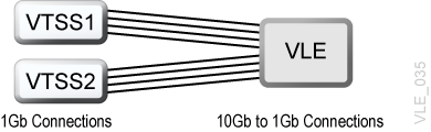
If an environment lacks additional network infrastructure to utilize the full 10 Gb bandwidth, and remote copy capability is not a requirement, up to eight (8) IFF/Replication ports can be directly connected to VTSS ports.
These ports will need to be converted to copper, and will only run at 1 Gb link speed (for potential total bandwidth of 8 Gb).
As noted earlier, separate subnets for all interfaces is considered a best practice since a link failure could down other VLE ports on the same subnet.
Table A-3 shows the ports that can be used for IFF/Replication traffic in this example.
Table A-3 VLE IFF/Replication Links
| Link | Device | Location | |
|---|---|---|---|
|
ixgbe0 |
ixgbe0 |
/SYS/MB |
|
|
ixgbe1 |
ixgbe1 |
/SYS/MB |
|
|
ixgbe2 |
ixgbe2 |
/SYS/MB |
|
|
ixgbe3 |
ixgbe3 |
/SYS/MB |
|
|
ixgbe4 |
ixgbe4 |
/SYS/MB/PCI3 |
IFF/Replication Traffic |
|
ixgbe5 |
ixgbe5 |
/SYS/MB/PCI3 |
IFF/Replication Traffic |
|
ixgbe6 |
ixgbe6 |
/SYS/MB/PCI5 |
|
|
ixgbe7 |
ixgbe7 |
/SYS/MB/PCI5 |
IFF/Replication Traffic |
|
ixgbe8 |
ixgbe8 |
/SYS/MB/PCI8 |
|
|
ixgbe9 |
ixgbe9 |
/SYS/MB/PCI8 |
IFF/Replication Traffic |
|
ixgbe10 |
ixgbe10 |
/SYS/MB/PCI10 |
IFF/Replication Traffic |
|
ixgbe11 |
ixgbe11 |
/SYS/MB/PCI10 |
IFF/Replication Traffic |
|
ixgbe12 |
ixgbe12 |
/SYS/MB/PCI11 |
IFF/Replication Traffic |
|
ixgbe13 |
ixgbe13 |
/SYS/MB/PCI11 |
IFF/Replication Traffic |
VTSS and VLE connections for this scenario:
| VTSS1 | IFF/REP1 | 192.168.1.11/24 |
| IFF/REP2 | 192.168.2.11/24 | |
| IFF/REP3 | 192.168.3.11/24 | |
| IFF/REP4 | 192.168.4.11/24 |
| VTSS2 | IFF/REP1 | 192.168.5.11/24 |
| IFF/REP2 | 192.168.6.11/24 | |
| IFF/REP3 | 192.168.7.11/24 | |
| IFF/REP4 | 192.168.8.11/24 |
| VLE | ixgbe4 | 192.168.1.10/24 |
| ixgbe5 | 192.168.2.10/24 | |
| ixgbe7 | 192.168.3.10/24 | |
| ixgbe9 | 192.168.4.10/24 | |
| ixgbe10 | 192.168.5.10/24 | |
| ixgbe11 | 192.168.6.10/24 | |
| ixgbe12 | 192.168.7.10/24 | |
| ixgbe13 | 192.168.8.10/24 |
Example 2: Multiple VTSS-to-VLE Layout with Network Infrastructure
This example illustrates a multiple VTSS-to-VLE network layout (Replication/IFF/Replication) with network infrastructure, as shown in Figure A-2.
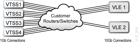
While direct connections were technically feasible with the quad-port NICs, that is no longer an option with dual-port 10 Gb NICs. However, the two 10 Gb ports can satisfy the bandwidth needs of the 16, 1 Gb connections. To do this, the customer must provide network infrastructure for the VLE ports to support 10 Gb link speeds and LACP aggregation, as well as proper routing if VTSS connections and the VLE ports are on different subnets.
VTSS connections for this scenario:
| VTSS1 | IFF/REP1 | 192.168.1.11/24 |
| IFF/REP2 | 192.168.2.11/24 | |
| IFF/REP3 | 192.168.3.11/24 | |
| IFF/REP4 | 192.168.4.11/24 |
| VTSS2 | IFF/REP1 | 192.168.1.12/24 |
| IFF/REP2 | 192.168.2.12/24 | |
| IFF/REP3 | 192.168.3.12/24 | |
| IFF/REP4 | 192.168.4.12/24 |
| VTSS3 | IFF/REP1 | 192.168.1.13/24 |
| IFF/REP2 | 192.168.2.13/24 | |
| IFF/REP3 | 192.168.3.13/24 | |
| IFF/REP4 | 192.168.4.13/24 |
| VTSS4 | IFF/REP1 | 192.168.1.14/24 |
| IFF/REP2 | 192.168.2.14/24 | |
| IFF/REP3 | 192.168.3.14/24 | |
| IFF/REP4 | 192.168.4.14/24 |
Caution:
The customer must ensure that routing is possible between all IFF/Replication connections and the VLE IP addresses.VLE connections for this scenario:
| Link | Device | Location |
| ixgbe4 | ixgbe4 | /SYS/MB/PCI3 |
| ixgbe5 | ixgbe5 | /SYS/MB/PCI3 |
| ixgbe10 | ixgbe10 | /SYS/MB/PCI10 |
| ixgbe11 | ixgbe11 | /SYS/MB/PCI10 |
Configure the IP addresses for the four IFF/Replication subnets on each VTSS.
| VLE1 | ixgbe4 | 192.168.1.10/24 |
| ixgbe5 | 192.168.2.10/24 | |
| ixgbe10 | 192.168.3.10/24 | |
| ixgbe11 | 192.168.4.10/24 |
Create an aggregation using ixgbe4 and ixgbe10 and assign a single IP address. This provides 20 Gb of bandwidth and redundancy.
Note:
Link failure will reduce bandwidth to 10 Gb.| VLE2 |
aggr2 |
ixgbe4
ixgbe10 |
192.168.1.10/24 |
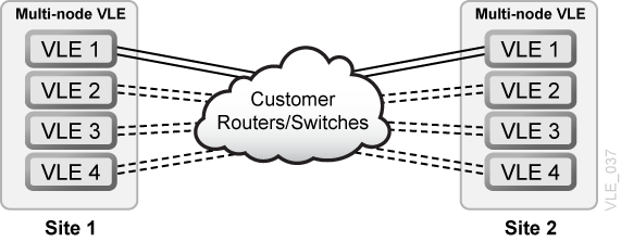
Example 3: Multi-node VLE Traffic
This example illustrates a network layout for a multi-node VLE.
Up to 16 VLE nodes may be configured in a multi-node VLE system that operates within a VLE private network (172.17.1.0/24).
Systems with one or two nodes use direct connect ports, while systems with three or more nodes require the Oracle 72 Switch.
Table A-4 shows the ports that can be used for multi-node traffic in this example.
Table A-4 VLE Multi-Node Links
| Link | Device | Location | |
|---|---|---|---|
|
ixgbe0 |
ixgbe0 |
/SYS/MB |
|
|
ixgbe1 |
ixgbe1 |
/SYS/MB |
|
|
ixgbe2 |
ixgbe2 |
/SYS/MB |
|
|
ixgbe3 |
ixgbe3 |
/SYS/MB |
|
|
ixgbe4 |
ixgbe4 |
/SYS/MB/PCI3 |
|
|
ixgbe5 |
ixgbe5 |
/SYS/MB/PCI3 |
|
|
ixgbe6 |
ixgbe6 |
/SYS/MB/PCI5 |
Multi-node traffic |
|
ixgbe7 |
ixgbe7 |
/SYS/MB/PCI5 |
|
|
ixgbe8 |
ixgbe8 |
/SYS/MB/PCI8 |
Multi-node traffic |
|
ixgbe9 |
ixgbe9 |
/SYS/MB/PCI8 |
|
|
ixgbe10 |
ixgbe10 |
/SYS/MB/PCI10 |
|
|
ixgbe11 |
ixgbe11 |
/SYS/MB/PCI10 |
|
|
ixgbe12 |
ixgbe12 |
/SYS/MB/PCI11 |
|
|
ixgbe13 |
ixgbe13 |
/SYS/MB/PCI11 |
Ports are pre-configured in an aggregate and are configured with an IP address based on the number of nodes in the multi-node VLE system:
| 1 | 172.17.1.1/24 |
| 2 | 172.17.1.2/24 |
| 3 | 172.17.1.3/24 |
| 4 | 172.17.1.4/24 |
| 5 | 172.17.1.5/24 |
| 6 | 172.17.1.6/24 |
| 7 | 172.17.1.7/24 |
| 8 | 172.17.1.8/24 |
| 9 | 172.17.1.9/24 |
| 10 | 172.17.1.10/24 |
| 11 | 172.17.1.11/24 |
| 12 | 172.17.1.12/24 |
| 13 | 172.17.1.13/24 |
| 14 | 172.17.1.14/24 |
| 15 | 172.17.1.15/24 |
| 16 | 172.17.1.16/24 |
Refer to the separate document Installing an Oracle 72 port 10Gb Ethernet TOR Switch in a VLE System for more information.
Example 4: VLE-to-VLE Remote Copy Traffic
This example illustrates a network layout for VLE-to-VLE remote copy traffic., as shown in Figure A-3.
The bottom ports in slot 5 and slot 8 are generally set aside for remote copy traffic to other VLE subsystems at remote sites. As with IFF/Replication traffic, these ports can be aggregated as one link or operated independently on unique subnets.
Table A-5 shows the ports that can be used for remote copy traffic in this example.
Table A-5 VLE Remote Copy Links
| Link | Device | Location | |
|---|---|---|---|
|
ixgbe0 |
ixgbe0 |
/SYS/MB |
|
|
ixgbe1 |
ixgbe1 |
/SYS/MB |
|
|
ixgbe2 |
ixgbe2 |
/SYS/MB |
|
|
ixgbe3 |
ixgbe3 |
/SYS/MB |
|
|
ixgbe4 |
ixgbe4 |
/SYS/MB/PCI3 |
|
|
ixgbe5 |
ixgbe5 |
/SYS/MB/PCI3 |
|
|
ixgbe6 |
ixgbe6 |
/SYS/MB/PCI5 |
|
|
ixgbe7 |
ixgbe7 |
/SYS/MB/PCI5 |
Remote Copy traffic |
|
ixgbe8 |
ixgbe8 |
/SYS/MB/PCI8 |
|
|
ixgbe9 |
ixgbe9 |
/SYS/MB/PCI8 |
Remote Copy traffic |
|
ixgbe10 |
ixgbe10 |
/SYS/MB/PCI10 |
|
|
ixgbe11 |
ixgbe11 |
/SYS/MB/PCI10 |
|
|
ixgbe12 |
ixgbe12 |
/SYS/MB/PCI11 |
|
|
ixgbe13 |
ixgbe13 |
/SYS/MB/PCI11 |
Caution:
Customers must ensure that routing is possible between all remote copy networks and ports.VLE connections for this scenario:
| Site #1 | VLE1 | 192.168.10.101/24 |
| VLE2 | 192.168.10.102/24 | |
| VLE3 | 192.168.10.103/24 | |
| VLE4 | 192.168.10.104/24 |
| Site #2 | VLE1 | 172.27.10.101/24 |
| VLE2 | 172.27.10.102/24 | |
| VLE3 | 172.27.10.103/24 | |
| VLE4 | 172.27.10.104/24 |
At least one pair of 10 Gb links are recommended between a VLE node at each site. However, additional links for other nodes may be optionally added if network bandwidth is available.