1 Introduction
This chapter introduces Oracle's StorageTek Virtual Library Extension (VLE) software and describes the components included in a typical VLE configuration. VLE is back-end disk storage for VTSS. The VLE solution consists of:
-
Virtual Tape Storage Subsystem (VTSS) hardware and microcode
-
Virtual Tape Control Subsystem (VTCS) software and Storage Management Component (SMC)
-
VLE hardware and software
-
On-demand capacity, scales-to-petabytes
-
Multiple redundant copies of data for the highest availability
-
All data can be encrypted at rest for security
-
Automatic data integrity checks for durability
-
Industry standard APIs at REST
-
Support for Migrating and Recalling Virtual Tape Volumes (VTVs) to, and from Oracle Archive Cloud
To VTCS, a VLE looks like a tape library except that the VTVs are stored in Virtual Multi-Volume Cartridges (VMVCs) on disk. With VLE, you can configure either a VLE and tape or a VLE only (for example, with Tapeless VSM configurations) back-end VTV storage solution. A VTSS can migrate VTVs to and recall them from a VLE, just as is done with a real tape library.
Caution:
-
If you have a VLE system, HSC/VTCS uses SMC communication services to communicate with the VLE. To ensure that these services are available during VTCS startup, Oracle recommends that you first issue the start command for HSC, then immediately issue the start command for SMC, while HSC is initializing.
-
Stopping SMC stops VTCS from sending messages to the VLE, which effectively stops data transfer. Therefore, you should ensure that VTCS activity is quiesced or VTCS is terminated before stopping SMC.
-
You cannot use AT-TLS with the SMC HTTP server if you are using VLE.
-
Tapeless VSM configurations, if you have only a single-node VLE attached to a specific VTSS and that VLE goes offline.Loss of access to any VTVs migrated to the VLE (not resident in the VTSS) until the VLE comes back online.
See the following sections for further information:
What's New for VLE 1.5.3
VLE 1.5.3 provides:
-
Support for 400 MB, 800 MB, 2 GB, 4 GB, and 32 GB VTV
-
An additional storage tier in the VSM solution. VTVs can now migrate from VTSS to VLE to provide fast access to recent data. Additionally, VTVs can transition from VLE storage to tape media (MVCs) for long term archive. You can control how VTVs are migrated and archived through the existing HSC Management and Storage Classes, providing full backward compatibility with previous configurations
-
Back-end disk storage shared between multiple VTSS systems, ensuring high-availability access to data
-
Oracle Cloud Encryption
Note:
For VLE 1.1 and higher, a ”VLE” is a collection of nodes interconnected with a private network.Refer tohttp://docs.oracle.com/cloud/latest/storagecs_common/index.html for further information on setting up a Cloud account, or "Network Requirements for Cloud Extended Storage."
Supported Platforms
VLE 1.5.3 has been tested with a very specific configuration. Using anything other than the approved configuration is not supported.
Note:
VLE 1.5.3 software works on both the old and new versions of the hardware stack. Within a single VLE cabinet, there can be no mixing of components.Stacks may be combined together, such as a VLE with the J4410 JBODS, then by a VLE with the DE2-24C JBODs, thereby, making a multi-node VLE.
VLE Hardware and Software
The VLE, which is a factory-assembled unit in a Sun Rack II Model 1242, includes the following hardware:
-
A server built on a Sun Server X4-4 platform
-
Four motherboard 10 Gb ports, two of which can be used for data transfer and other purposes. Two are dedicated for management, service, and support
-
A service (ILOM) port
-
Four dual port 10 Gb Fibre Optic network cards (six ports available) plus two 10 Gb Copper ports
-
One or more Oracle Storage Drive Enclosure DE2-24Cs (DE2-24C) that contain disk (HDDs) in a ZFS RAID array, scalable in effective capacities starting at 200 TB for a single JBOD VLE (assuming a 4 to 1 compression ratio when the data is migrated to the VLE)
-
A DVD drive
The VLE software consists of:
-
Oracle Solaris 11 Operating System
-
ZFS file system and MySQL database
-
The VLE application software
Figure 1-1 shows the VLE subsystem architecture
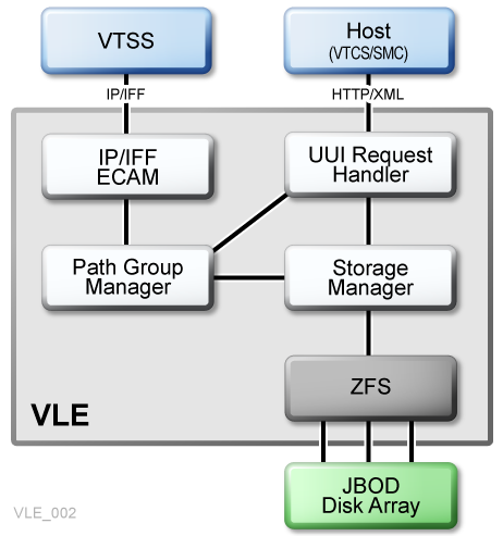
As Figure 1-1 shows, the VLE application software consists of:
-
HTTP/XML is the data protocol for host-to-VLE communications.
-
The Universal User Interface (UUI) Request Handler, which processes UUI requests from, and produces responses to Storage Management Component (SMC) and Virtual Tape Control Software (VTCS). The UUI Request Handler determines which VLE components are used to service a request.
UUI Request Handler calls:
-
The PathGroup Manager to schedule VTV migrates and recalls. The PathGroup Manager manages all Path Groups, where each Path Group manages a single VTV data transfer between the VTSS and the VLE.
-
The Storage Manager to schedule all report generation.
-
-
The VLE Storage Manager component manages the VMVC/VTV data and meta data on the VLE. The VLE Storage Manager stores VTV data on and retrieves it from the ZFS on the JBOD array.
-
TCP/IP/IFF is the data protocol for host to VLE communications, where the IP/IFF/ECAM component handles communications between the VTSS and the VLE.
Single Node VLE Configuration
Figure 1-2 shows a single node VLE configuration.
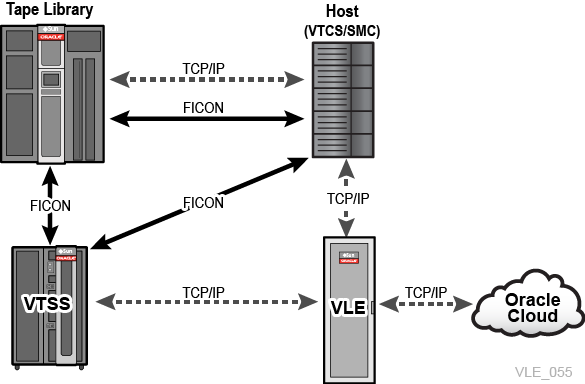
As Figure 1-2 shows (where 1 is the MVS host and 2 is the library):
-
Multiple TCP/IP connections (between the VTSSs' IP ports and the VLEs' IP ports) are supported, as follows:
-
A single VLE can connect up to 8 VTSSs, so VTSSs can share VLEs.
-
A single VTSS can connect to up to 4 VLEs to increase buffer space for heavy workloads.
-
-
A single VTSS can be attached to:
-
Only RTDs
-
Only other VTSSs (clustered)
-
Only VLEs
-
Any combination of the above
-
-
TCP/IP is the only supported protocol for connections between the VLE and the VTSS and for connections between the VLE and hosts running SMC and VTCS.
Multi-Node VLE Systems
Multi-node VLE systems enable massive scaling of the VLE storage system. You can construct multi-node systems that consist of one to 64 nodes, with multiple nodes interconnected by a private network. A multi-node VLE appears to SMC/VTCS as a single VLE. The VLE ships with 4 TB JBODs, so a single VLE can scale between 200 TB (for a one JBOD system) and 100 PB (for a fully populated 64-node VLE).
Note:
These are effective capacities, assuming 4:1 compression.VLE is architected for up to 64 nodes, but has only been validated for up to 16 nodes.Figure 1-3 shows a VLE multi-node complex, where the nodes are cross-connected into a dedicated 10 GE switch so that each node can access any other node in the complex, as described in the figure below.
Note:
A multi-node VLE can be any combination of 1.5.0, 1.5.1, 1.5.1.A1, 1.5.2, 1.5.2.A1 or 1.5.3 application code levels, but all nodes should be upgraded to 1.5.3 as soon as possible.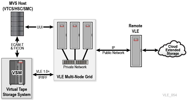
Caution:
It is recommended that all nodes be running at VLE 1.5.3 and not mixed between 1.5.0, 1.5.1, 1.5.1.A1, 1.5.2 or 1.5.2.A1 with 1.5.3, except during the time frame needed for upgrades.VLE-to-VLE Data Transfer
The VLE storage system can manage data transfers independently of the VTSS, which frees VTSS resources for front-end (host) workload, which improves the overall VTSS throughput.
Example:
-
If your migration policies specify that there should be two VLE copies of a VTV (either in the same or separate VLEs), then the first migration to a VLE will cause data to be transferred from the VTSS. All subsequent VLE migrations for the VTV may be achieved through a VLE to a VLE copy. This reduces the VTSS cycle times required to migrate all copies of a VTV.
-
If your environment runs:
-
VLE 1.2 or higher
-
VTCS 7.1 (with the supporting PTFs) or VTCS 7.2 and higher
You can use VTCS to define more VLE devices than there are VTSS-to-VLE paths through the
CONFIG STORMNGR VLEDEVparameter. If you use this addressing scheme, then the VTSS resources used to migrate all of the VTV copies to VLE are reduced even further. This is because the path from the VTSS to the target VLE is only reserved when the data transfer is direct from the VTSS to the VLE. For all VLE VRTD actions, a path from the VTSS is only reserved when VTSS data transfer is required. This feature is referred to as Autonomous Device Support (ADS).
-
VTV Encryption
The encryption feature enables encryption of VMVCs written to the VLE system. Encryption is enabled on a per node basis, through an encryption key stored on the node, backed up on a USB device. Encryption is entirely managed through the VLE GUI; the host software has no knowledge of encryption, as the VLE de-encrypts VTVs that are recalled to the VTSS.
Note:
Encryption can only be enabled on an empty VLE, with no VMVC(s) defined. Enabling encryption on a VLE that already contains customer data cannot be done. Consequently, the decision whether to encrypt must be made during the planning stage of the VLE install.When you first define new encrypted VMVCs, a USB stick must be present. The keys are backed up onto that USB stick. Before you define additional VMVCs, ensure that the original USB stick has been inserted, so that the old and new keys are synchronized and backed-up. It is the responsibility of the customer to manage the USB stick as backup when creating encrypted VMVCs. Though you can create encrypted VMVCs without the USB stick being present, you will not be able to mount or read any of the VMVCs without the correct encryption key.
Note:
The USB stick should be formatted in FAT or FAT32 on a Windows workstation/server, prior to inserting it into a USB slot of a VLE so that the VLE will recognize it. NTFS and exFAT formatted USB sticks are not supported by VLE.VTV Deduplication
Deduplication eliminates redundant data in a VLE complex. Deduplication, which is controlled by the STORCLAS statement DEDUP parameter, increases the effective VLE capacity, and is performed by the VLE before the VTV is written to a VMVC.
To assess deduplication results, enable deduplication, monitor the results with the SCRPT report, and fine tune deduplication as necessary. The SCRPT report provides the approximate ”reduction ratio” for the deduplicated data, which is uncompressed GB divided by used GB. The Reduction Ratio, therefore, includes both VTSS compression and VLE deduplication. A larger reduction ratio indicates more effective compression and deduplication.
For example, the VTSS receives 16 MB of data, compresses it to 4 MB, and writes the compressed data to a VTV. VLE subsequently deduplicates the VTV to 2 MB and writes it to a VMVC. Thus, the reduction ratio is 16 MB divided by 2 MB, or 8.0:1.
Frame Size Control
Frame Size Control specifies the use of Jumbo Frames on each copy link:
Note:
The infrastructure between the VSM and VLE, or between VLEs, must support Jumbo Frames before this will work. If any portion of the infrastructure between these connections does not support Jumbo Frames, it will not work.-
If your TCP/IP network supports Jumbo Frames, enabling this option can improve network performance.
-
You enable Jumbo Frames by selecting the
Jumbo Framescheck-box on thePort Card Configuration Tab. Selecting this check-box sets the MTU (Maximum Transmission Unit) value to 9000 for the port. -
It is recommended that Jumbo Frames be enabled on links that are set for VLE-to-VLE transfer.
Oracle Cloud Extended Storage
VLE 1.5.2 and higher offers connection from the VLE to the Oracle Cloud. VLE can be configured to optionally migrate and recall customer data directly to and from the Oracle Cloud. VLE configuration options support any combination of data storage in the local VLE disk pool and/or the Oracle Cloud. VLE supports three Oracle Cloud options: Oracle Cloud, Oracle Cloud (Archive), and Encryption within Oracle Cloud. See below for further explanation of the supported Oracle Cloud options.
Oracle's Cloud Extended Storage is an option that allows the customer additional storage capacity. Refer tohttp://docs.oracle.com/cloud/latest/storagecs_common/index.html for further information on setting up a Cloud account, or "Network Requirements for Cloud Extended Storage."
For information regarding metered and non-metered accounts, see:
-
http://docs.oracle.com/cloud/latest/trial_paid_subscriptions/CSGSG/toc.htm -
For up-to-date Cloud information, see:
-
For further assistance, see:
http://docs.oracle.com/cloud/latest/storagecs_common/index.html
Oracle Storage Cloud Service – Object Storage
With support for VLE 1.5.2 and higher, storing data in the Oracle Storage Cloud - Object Storage is much like storing data in the VLE local disk pool. The following steps outline what is needed to configure a VLE for storing VTV in the Storage Cloud.
The information needed, is:
Note:
The Oracle CSE will need to retrieve the customer's Oracle Cloud account information to create the initial connection between the VLE and the Oracle Storage Cloud Service - Object Storage.-
Account Name
-
User Name
-
User Password
-
Authorization URL
Note:
MVC ranges are determined by the customer. They are used to configure VTCS host software and given to the Oracle support team for configuration of the VLE.
If the VLE will store VTV data on its local disk pool as well as the Storage Cloud, there will be two VMVC pool ranges defined and configured in the VLE:
-
A vMVC range for VLE local disk pool storage
-
A vMVC range for the VLE Oracle Cloud storage
Once VMVC definitions are configured in the VLE, VTV Migrate, Recall, and VLE Copy operations can be expected to behave much the same as all VLE operations that use the VLE local storage pool.
Note:
The performance of VLE-to-Cloud data transfer performance is subject to IP bandwidth and delay, as well as the Storage Cloud performance capabilities.Oracle Storage Cloud Service – Archive Storage
With support for VLE 1.5.3 and higher, storing data in the Cloud Archive is much like storing data in the VLE local disk pool, but there are some exceptions regarding a recall of data stored in the Oracle Storage Cloud Service – Archive Storage.
The steps for setting up a VLE for using the Oracle Storage Cloud Service – Archive Storage are similar to the steps for the Oracle Storage Cloud for Object Storage.
The information needed, is:
Note:
The Oracle CSE will need to retrieve the customer's Oracle Cloud account information to create the initial connection between the VLE and Oracle Cloud Archive. Cloud Archive account information is the same as Storage Cloud-
Account Name
-
User Name
-
User Password
-
Authorization URL
MVC ranges are determined by the customer. They are used to configure VTCS host software and given to the Oracle support team for configuration of the VLE. The customer will need to provide up to three vMVC ranges when using Cloud Archive:
-
A vMVC range for VLE local disk pool storage
-
A vMVC range for the VLE Oracle Cloud storage
-
A vMVC range for the VLE Oracle Cloud (Archive) storage
When creating vMVCs on the VLE the Oracle support person selects an ’archive' flag for vMVCs that will use Cloud Archive. This is what triggers the ’archive' functionality within the Oracle Cloud.Once VMVC definitions are configured in the VLE, VTV Migrate, Recall, and VLE Copy operations are possible for all three vMVC ranges but there some exceptions for the Cloud Archive range of vMVCs.
Note:
For a more in-depth discussion of Migrate, Restore and Recall, refer to the Host Software Configuration Guide for Virtual Library Extension (VLE) 1.5.Migrate
VTV migrate operations perform the same as for VTVs migrated to VLE local disk pool or Oracle Storage Cloud Service – Object Storage. Once the VTV migrate to the Storage Cloud is complete, the VTV will immediately move to the Cloud Archive.
Note:
With VTVs immediately moved to Archived status, users will be unable to immediately recall or use the VTV(s) as a source, for a VLE-to-VLE copy operation.Recall
Once a VTV is moved to Cloud Archive after a migrate, it cannot be recalled until it has been restored (moved from the Cloud Archive to the Storage Cloud).
Restore
VTVs that are to be restored are identified by the customer and are manually (or host job) restored using a restore command via the SMC UUI interface.
Note:
Oracle service level agreement (SLA) to restore a VTV is 4 hours. Multiple restore VTV commands can be initiated at the same time.Query Restore can be issued to the VTVs that are in the restore process to get current progress (Complete, In progress). Restore operations within the Cloud Archive can be expected to behave much the same as all VLE operations that use the VLE local storage pool.
The performance of VLE-to-Cloud data transfer performance is subject to IP bandwidth and delay, as well as the Oracle Cloud performance capabilities.
Oracle Cloud Encryption (Support for VLE 1.5.3 and Higher)
The Oracle Storage Cloud Service – Object Storage and the Oracle Storage Cloud Service – Archive Storage support Encryption. Controlling Encryption in either of the Oracle Cloud offerings is controlled at the vMVC boundary, That is, if a vMVC is created with the Encryption flag set, all of the VTVs in that vMVC will be encrypted. Migrate and recall operations for encrypted VTVs behave exactly the same for each of the respective Clouds (Archive and non-archive), as described previously.
The only behavior difference is a performance decrease of 10% for encrypted VTVs. The steps for setting up the VLE for using the Oracle Cloud Encryption are very similar to steps described in "Oracle Storage Cloud Service – Object Storage" and "Oracle Storage Cloud Service – Archive Storage".
Note:
The Oracle CSE will need to customer Oracle Cloud account information to create the initial connection between the VLE and Oracle Cloud.Archive Cloud account information is the same as Storage Cloud account information.
The information needed, is:
-
Account Name
-
User Name
-
User Password
-
Authorization URL
MVC ranges are determined by the customer. They are used to configure VTCS host software and given to the Oracle support team for configuration of the VLE. The customer will need to provide up to three vMVC ranges when using Oracle Cloud with Encryption :
-
A vMVC range for VLE local disk pool storage
-
A vMVC range for the VLE Oracle Cloud storage (with or without Encryption)
-
A vMVC range for the VLE Oracle Cloud (Archive) storage (with or without Encryption)
Note:
When creating vMVCs on a VLE, an Oracle support person sets an encryption flag for any vMVCs that will contain encrypted VTVs.
Once VMVC definitions are configured in the VLE, VTV Migrate, Recall, and VLE Copy operations for Encrypted vMVCs behave exactly as described in "Oracle Storage Cloud Service – Object Storage" and "Oracle Storage Cloud Service – Archive Storage". The Oracle Cloud website can be reviewed for information pertaining to the Encryption feature as it is handled within the Oracle Cloud.
Customer Checklist: Setting Up VLE for Oracle Cloud Storage
Retrieve the following parameters at least one week prior, for the Oracle Field Engineer to be ready to setup VLE 1.5 to connect to Oracle Cloud Storage.
Note:
If these values are not readily available, setting up Cloud connectivity will be delayed until the values are available.Table 1-1 Parameters for Cloud Connectivity
| Value | Description | Comment |
|---|---|---|
|
Oracle Cloud Storage Account |
A valid Cloud Storage account, provided by Oracle. Customers should have received an email with account information |
The Service Engineer will need the following details when setting up the VLE for Oracle Cloud: URL, Account Name, User Name and Password. |
|
Dedicated Ethernet port on VLE |
It is strongly recommended that one or more Ethernet ports on the VLE be dedicated to Cloud traffic. |
The dedicated Ethernet ports should have connectivity to this subnet. |
|
Dedicated Cloud subnet |
A dedicated subnet, provisioned by customer's Information Technology (IT) Department, so Cloud data traffic can be routed through it. |
The dedicated Ethernet ports should have connectivity to this subnet. |
|
Static IP Address(es) |
One or more valid IP address(es) provided by the Information Technology (IT) Department. |
The IP addresses will be assigned to the Ethernet ports. If multiple Ethernet ports and a single IP address is desired, then the Ethernet ports will be aggregated. |
|
Gateway, Network Number and Network Mask |
Values to be used when setting the IP address, provided by the Information Technology (IT) Department. |
These values should be readily available from the Information Technology (IT) Department. |