8 Configuring IPsec
This chapter explains how to configure IPsec using Oracle Communications IP Service Activator.
About VRF-Aware IPsec
IP Service Activator allows you to configure VRF-Aware IPsec tunnels using the following configuration policies:
-
Customer IPsec Access
-
Public IPsec
The VRF-Aware IPsec feature allows you to map IPsec tunnels that terminate on a shared public interface to specific Virtual Routing and Forwarding (VRF) instances. This allows you to map IPsec tunnels to MPLS VPNs extending customer VPN access to users that are not directly reachable via dedicated WAN links.
VRF-Aware IPsec Procedures and Configuration Policies
For details on implementing VRF-Aware IPsec using the IP Service Activator including step-by-step procedures, see IP Service Activator online Help.
VRF-aware IPsec topics in the online Help include:
-
VRF-Aware IPsec - Concepts and Examples
-
Creating a redundant Front Door VRF configuration
-
Creating a Front Door VPN and Site
-
Creating a Customer IPsec Site
-
Configuration Policy - Customer IPsec Access
-
Configuration Policy - Public IPsec
Example of VRF-Aware IPsec Implementation
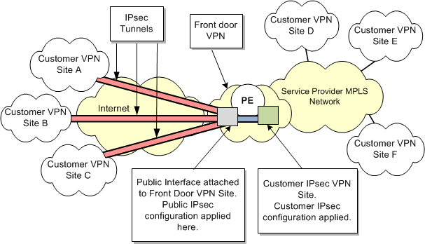
Figure 8-1 illustrates an example VRF-Aware IPsec implementation.
Figure 8-1 VRF-Aware IPsec Implementation

Description of ''Figure 8-1 VRF-Aware IPsec Implementation''
A service provider has an MPLS-enabled core network and provides a customer with VPN access between customer sites D, E, and F.
Additional remote customer VPNs (with customer sites A, B, and C) lie outside the service provider's core network. These remote sites are not directly attached to the WAN supporting the Customer MPLS VPN. Instead, they are connected to the service provider's MPLS network through an untrusted intermediary, such as an unsecured Internet connection.
In order to connect customer sites A, B, and C to the customer VPN provisioned in the MPLS-enabled core network, IPsec tunnels are provisioned across the untrusted intermediary connection.
These tunnels deliver encrypted data to a PE router (PE1). Incoming packets are decrypted and passed on through the Customer VPN on the service provider's MPLS network. Similarly, packets arriving at PE1 from the customer VPN which are destined for sites A, B or C, are encrypted at PE1 and sent over the IPsec tunnels, to be decrypted at the target site.
VRF-Aware IPsec Details
Traffic moving from Customer Sites A, B and C to Customer VPN Sites D, E, and F, is encrypted at the start of the IPsec tunnels. Packets travel from these IPsec sites over a publicly accessible network such as the Internet, through the IPsec tunnels to the public interface (2) on PE1.
The public interface is included in the Front Door VPN Site and this is where the packets are decrypted.
At the Customer IPsec site, which is a member of both the Front Door VPN, and the Customer VPN on the service provider's MPLS network, the appropriate MPLS labelling is applied for the packets to be transported over the Customer MPLS VPN.
Going in the other direction, MPLS-labelled packets arrive at the Customer IPsec site. At the Customer IPsec site, the MPLS labels are stripped and the packets are passed to the Front Door site. At the Front Door site (which includes the public interface), the packets are encrypted for transport over the IPsec tunnels. At the target Customer Sites, at the ends of the IPsec tunnels, the packets are decrypted.
The IPsec tunnels configured between the Remote Sites and the PE device connect to the PE through the same public interface (labelled 2 on the diagram) at the Front Door Site in the Front Door VPN.
Configuration of the Front Door Site is performed using the Public IPsec configuration policy.
The Customer IPsec Site (labelled 3) is a member of both the Front Door VPN and the Customer MPLS VPN. The PE device containing the public interface is associated with Customer IPsec Site.
Configuration of the Customer Site is performed using the Customer IPsec configuration policy.
To support the connection between the end of an IPsec tunnel and the customer VPN in the service provider MPLS network, a small VPN, known as the Front Door VPN, is used. There are two VRF instances inside this VPN:
-
A Front Door VRF (F-VRF) at the Front Door site
-
A Customer VRF (C-VRF) at the Customer IPsec site
The Front Door VRF is used to isolate the public interface from the global routing tables on the PE. The Customer VRF provides connectivity to the Customer MPLS VPNs.
One or more IPsec tunnels can be attached to the PE using a single public interface. The tunnels then terminate at the appropriate C-VRF. The C-VRF for each of the IPsec tunnels may be different depending on the VRF referenced from the customer specific IPsec configuration.
IP Service Activator's VRF-Aware IPsec provisioning support includes:
-
For the MPLS VPN portion, provisioning and activation of Customer VPN Sites and VPNs.
-
For the IPsec portion, provisioning and activation of IPsec configuration policies and their association to the Front Door Site and specific Customer MPLS VPN sites.
For step-by-step procedures on how to provision VRF-aware IPsec, refer to the Online Help. See "VRF-Aware IPsec Procedures and Configuration Policies" for the list of available topics.
Using Configuration Policies for IPsec Provisioning
In order to use the Public IPsec and Customer IPsec configuration policies, the .policy file containing these policies must be loaded into IP Service Activator.
To load the IPsec configuration policy files:
-
Right-click on your Domain and select Properties.
-
On the Domain dialog box, select the Setup property page.
-
Browse to the IPSecPolicyTypes.policy file. Click Load.
-
Click OK and commit the transaction.
For step-by-step procedures on how to provision VRF-aware IPsec, refer to IP Service Activator online Help. See "VRF-Aware IPsec Procedures and Configuration Policies" for the list of available topics.