D Configuring SL8500 Library Communications
The SL8500 is different from other LSMs, and the way it communicates with HSC is also different, as explained in this appendix.
TCP/IP Communications - Important Considerations
The following topics are discussed here:
SL8500 TCP/IP Connections
When you create an SL8500 library complex by connecting libraries together with passthru ports, all hosts must connect to only one library in the complex— preferably to the first or rightmost library.
For the complex, there are three types of TCP/IP connections for SL8500 discussed in the following sections:
-
"Dual IP Connections" - A redundancy feature to allow up to two connections to the first library of a complex.
-
"Multiple SL8500 Library Connections" - Starting with the SL8500 3.9x firmware release, an SL8500 complex is capable of network connecting up to 4 libraries to HSC. This enhances connecting redundancy to the complex compared to dual TCP/IP.
-
"Multiple TCP/IP Redundant Electronics" - Starting with the SL8500 6.x firmware release, an SL8500 complex is capable of redundant electronics of the library controller with network connecting up to 16 libraries in pairs (one active and one standby) to HSC. This enhances hardware reliability to the complex compared to the other 2 types.
Note:
It is crucial that you read completely these sections to understand these procedures.
Shared Networks
The following are some examples of issues that can arise when you connect an SL8500 to a shared network.
-
A TCP/IP-connected library can handle standard host traffic but it cannot resolve floods of Address Resolution Protocol (ARP) broadcasts. For this reason, it is best to attach the library on a controlled network, such as behind a switch or router.
Later generation networks, such as 1000Base-T and Gig-E, support earlier communication modes; however, devices that are communicating with the library may transmit data at bandwidths that could overwhelm the library.
It is best to attach the library on a controlled network, such as with a switch that can isolate the library from network broadcasts.
-
When you connect the library on shared networks and broadcasts are sent to all network nodes, they may also be directed to the library (even though it does not need them).
During the time the library is receiving these irrelevant broadcasts, it cannot receive from or respond to other requests in a timely fashion. This heavy broadcast traffic on the network can saturate the library to the point that, to the host, it may appear that the TCP/IP connection has been lost. It may also result in Overdue Response Handler (ORH) messages on the host system.
-
Heavy network traffic can also overwhelm the Ethernet controller causing the processor to continuously reset and re-initialize the controller, then recover the host-to-library communications.
Dual IP Connections
The LMUPATH control statement allows users to define network LMU attachments (refer to the ELS Command, Control Statement, and Utility Reference). In a dual IP connection environment for an SL8500, specify a second LMUADDR parameter to define dual IP. HSC automatically determines whether or not the connection is dual IP or dual LMU.
Note:
Vary the ACS offline and back online to pick up the revised LMUPATH statement that includes the second connection.Figure D-1 and Figure D-2 show examples of a dual IP connection for the HSC.
Two SL8500 Network Connections - Two Mainframe IP Addresses
To establish two dedicated routes on different subnetworks from the HSC to two dedicated routes to the SL8500, use the process described in this section. To configure the SL8500 dual TCP/IP feature, refer to StreamLine SL8500 Modular Library System Dual TCP/IP Feature or StreamLine SL3000 Modular Library System Installation Guide.
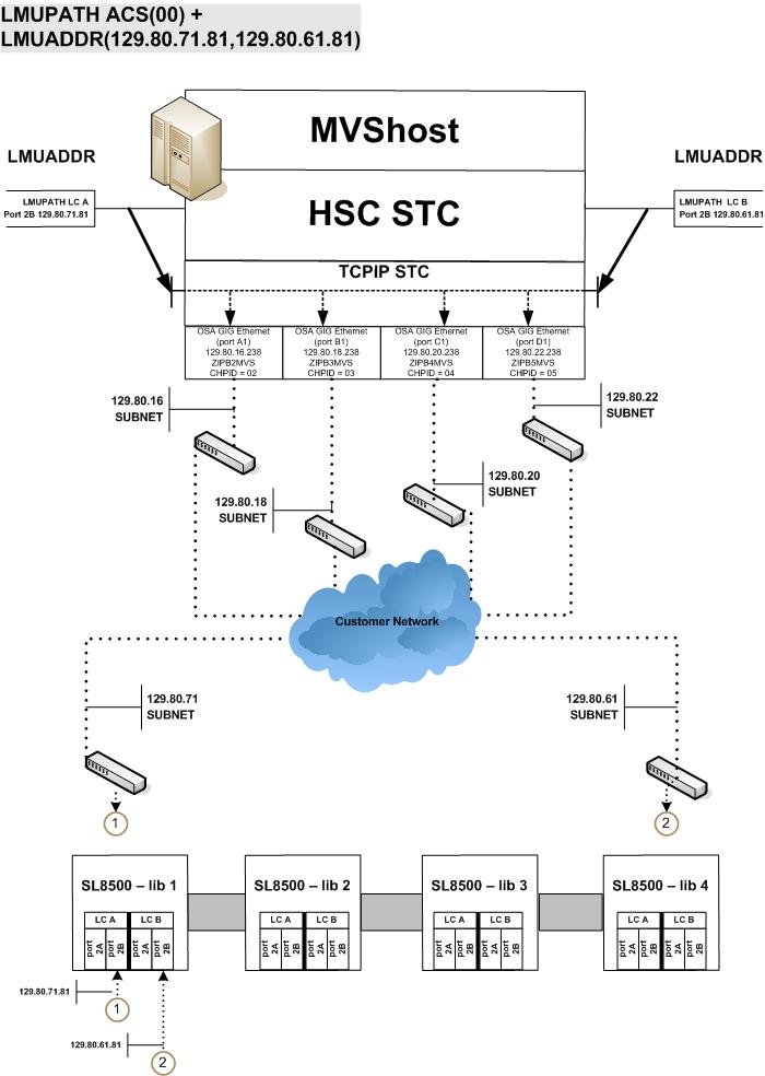
Figure D-1 shows dual IP connections with two SL8500 network connections.
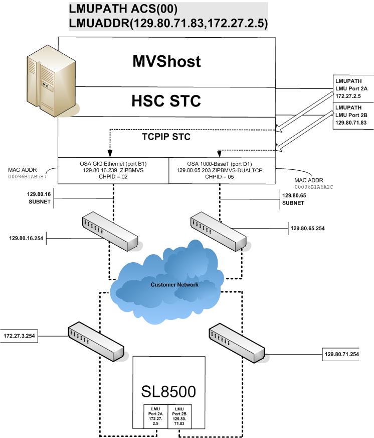
-
Complete the Network Entries Worksheet (see Table D-1 for a sample) for each set of two dedicated routes to the SL8500. The worksheet can be found in the StreamLine SL8500 Modular Library System Dual TCP/IP Feature document.
-
Define a second DEVICE and LINK statement in your TCP/IP profile data set for a second mainframe network connection.
Example:
; OSA CARD #1
DEVICE ECCQD01 MPCIPA   NONROUTER AUTORESTART
LINK   ZIPBMVS IPAQENET ECCQD01

; OSA CARD #2
DEVICE ECCQA01  MPCIPA   NONROUTER AUTORESTART
LINK   ZIPB2MVS IPAQENET ECCQA01
-
Define a second home address in your TCP/IP profile data set.
Example:
HOME
129.80.16.239 ZIPBMVS
129.80.65.203 ZIPB2MVS
-
Define a second router on the second subnetwork in the routing paragraph of your TCP/IP profile data set. Remember that you must also configure the SL8500 routing tables according to the instructions described in the StreamLine SL8500 Modular Library System Dual TCP/IP Feature document.
Example:
BEGINROUTES
;    NETWORK MASK                 FIRSTHOP      LINKNAME  PACKETSIZE
ROUTE 129.80.16.0/24              =             ZIPBMVS   MTU 1492
ROUTE 129.80.65.0/24              =             ZIPB2MVS  MTU 1492
ROUTE 172.27.2.5 HOST             129.80.16.254 ZIPBMVS   MTU 1492
ROUTE 129.80.71.83 HOST           129.80.65.254 ZIPB2MVS  MTU 1492
ROUTE DEFAULT 129.80.16.254                     ZIPBMVS   MTU 1492
ROUTE DEFAULT 129.80.65.254                     ZIPB2MVS  MTU 1492
ENDROUTES
-
Define two dedicated static routes to the SL8500 destination port (2A and 2B) IP addresses over two different routers.
Example:
;                         NETWORK MASK  ROUTER        LINKNAME   PACKETSIZE
ROUTE Sl8500-port-2A-IP-Address HOST    129.80.16.254 MVSHOST1   MTU 1492
ROUTE Sl8500-port-2B-IP-Address HOST    129.80.64.254 MVSHOST2   MTU 1492

BEGINROUTES
;                      NETWORK MASK     FIRSTHOP      LINKNAME   PACKETSIZE
ROUTE 129.80.16.0/24                    =             ZIPBMVS    MTU 1492
ROUTE 129.80.65.0/24                    =             ZIPB2MVS   MTU 1492
ROUTE 172.27.2.5       HOST             129.80.16.254 ZIPBMVS    MTU 1492
ROUTE 129.80.71.83     HOST             129.80.65.254 ZIPB2MVS   MTU 1492
ROUTE DEFAULT 129.80.16.254                           ZIPBMVS    MTU 1492
ROUTE DEFAULT 129.80.65.254                           ZIPB2MVS   MTU 1492
ENDROUTES
-
Start the second mainframe network connection device.
V TCPIP,tcp-stc-name,START,device_name
-
Define a second LMUADDR parameter for the port 2A IP address on the SL8500.
Example:
LMUPATH ACS(00) LMUADDR(129.80.71.83,172.27.2.5)
-
Enter the LMUPDEF command containing the LMUPATH statements that define the host name or IP address for each ACS.
LMUPDEF DSN(’xxx.xxx.xxx(xxx)')In the following example, LMUPDEF loads LMUPATH parameters from YOUR.DSN(MEMBER)
LMUPDEF DSN(’YOUR.DSN(MEMBER)') -
Allow the trained SL8500 service representative to enter the network connections to the SL8500 library for either port 2A and 2B, whichever is applicable.
-
Vary the ACS offline and back online to pick up the revised LMUPATH statement that includes the second connection. This can be done one host at a time to minimize down time.
Sample Configuration - Two Dedicated Routes
Figure D-2 shows a sample configuration with two dedicated routes, followed by the statements that apply to it.
Setup Statements and Displays
The following information shows the statements and displays used in Figure D-2.
HSC LMUPDEF PARMLIB Member
OPTION TITLE('DUAL TCPIP CONNECTING TO SL8500')
LMUPATH ACS(00) LMUADDR(129.80.71.83,172.27.2.5)
TCP/IP Profile Data Set
; OSA CARD #1
DEVICE ECCQD01 MPCIPA   NONROUTER AUTORESTART
LINK   ZIPBMVS IPAQENET ECCQD01

; OSA CARD #2
DEVICE ECCQA01 MPCIPA   NONROUTER AUTORESTART
LINK   ZIPB2MVS IPAQENET ECCQA01

HOME
   129.80.16.239 ZIPBMVS
   129.80.65.203 ZIPB2MVS

BEGINROUTES
;                  NETWORK MASK   FIRSTHOP      LINKNAME       PACKETSIZE
ROUTE 129.80.16.0/24              =             ZIPBMVS        MTU 1492
ROUTE 129.80.65.0/24              =             ZIPB2MVS       MTU 1492
ROUTE 172.27.2.5   HOST           129.80.16.254 ZIPBMVS        MTU 1492
ROUTE 129.80.71.83 HOST           129.80.65.254 ZIPB2MVS       MTU 1492
ROUTE DEFAULT 129.80.16.254                     ZIPBMVS        MTU 1492
ROUTE DEFAULT 129.80.65.254                     ZIPB2MVS       MTU 1492

ENDROUTES

INCLUDE ZIP.TCPIP.PROFILES(COMMON)

START ECCQD01
START ECCQA01
TCP/IP Console Displays
D TCPIP,TCPIP,NETSTAT,DEV
EZZ2500I NETSTAT CS V1R4 TCPIP 229
DEVNAME: LOOPBACK          DEVTYPE: LOOPBACK
 DEVSTATUS: READY
 LNKNAME: LOOPBACK          LNKTYPE: LOOPBACK    LNKSTATUS: READY
  NETNUM:  0   QUESIZE: 0
  BYTESIN: 1781074               BYTESOUT: 1781074
  ACTMTU:  65535
 BSD ROUTING PARAMETERS:
  MTU SIZE: 00000             METRIC: 00
  DESTADDR: 0.0.0.0           SUBNETMASK: 0.0.0.0
 MULTICAST SPECIFIC:
  MULTICAST CAPABILITY: NO

DEVNAME: ECCQD01           DEVTYPE: MPCIPA
 DEVSTATUS: READY         CFGROUTER: NON  ACTROUTER: NON
 LNKNAME: ZIPBMVS           LNKTYPE: IPAQENET    LNKSTATUS: READY
  NETNUM:  0   QUESIZE: 0   SPEED: 0000001000
  BYTESIN: 34704496              BYTESOUT: 11207410
  IPBROADCASTCAPABILITY: NO
  ARPOFFLOAD: YES  ARPOFFLOADINFO: YES
  ACTMTU:  8992
  INBPERF: BALANCED
 BSD ROUTING PARAMETERS:
  MTU SIZE: 00000             METRIC: 00
  DESTADDR: 0.0.0.0           SUBNETMASK: 255.255.255.0
 MULTICAST SPECIFIC:
  MULTICAST CAPABILITY: YES
  GROUP             REFCNT
  -----             ------
  224.0.0.1         0000000001

DEVNAME: ECCQA01           DEVTYPE: MPCIPA
 DEVSTATUS: READY         CFGROUTER: NON  ACTROUTER: NON
 LNKNAME: ZIPB2MVS          LNKTYPE: IPAQENET    LNKSTATUS: READY
  NETNUM:  0   QUESIZE: 0   SPEED: 0000000100
  BYTESIN: 147508801             BYTESOUT: 2188246
  IPBROADCASTCAPABILITY: NO
  ARPOFFLOAD: YES  ARPOFFLOADINFO: YES
  ACTMTU:  1492
  INBPERF: BALANCED
 BSD ROUTING PARAMETERS:
  MTU SIZE: 00000             METRIC: 00
  DESTADDR: 0.0.0.0           SUBNETMASK: 255.255.255.0
 MULTICAST SPECIFIC:
  MULTICAST CAPABILITY: YES
  GROUP             REFCNT
  -----             ------
  224.0.0.1         0000000001
3 OF 3 RECORDS DISPLAYED
D TCPIP,TCPIP,NETSTAT,ROUTE
EZZ2500I NETSTAT CS V1R4 TCPIP 250
DESTINATION      GATEWAY          FLAGS     REFCNT  INTERFACE
DEFAULT          129.80.16.254    UGS       000003  ZIPBMVS
DEFAULT          129.80.65.254    UGS       000002  ZIPB2MVS
127.0.0.1        0.0.0.0          UH        000003  LOOPBACK
129.80.16.0      0.0.0.0          US        000002  ZIPBMVS
129.80.16.239    0.0.0.0          UH        000000  ZIPBMVS
129.80.65.0      0.0.0.0          US        000000  ZIPB2MVS
129.80.65.203    0.0.0.0          UH        000000  ZIPB2MVS
129.80.71.83     129.80.65.254    UGHS      000001  ZIPB2MVS
172.27.2.5       129.80.16.254    UGHS      000001  ZIPBMVS
9 OF 9 RECORDS DISPLAYED
HSC Display Showing SL8500 Connection
D ACS
SLS0000I D ACS
SLS1000I ACS 00 STATUS: CONNECTED 334
ACTIVE QUEUE ELEMENTS                  2
COMPATIBILITY LEVELS: HSC=13, LMU=13
DUAL LMU NOT CONFIGURED
IP ADDR  129.80.71.83 ONLINE
IP ADDR  172.27.2.5 ONLINE
SCRATCH VOLUMES AVAILABLE......      210
FREE CELLS AVAILABLE...........     2008
D TCPIP,TCPIP,NETSTAT,HOME
EZZ2500I NETSTAT CS V1R4 TCPIP 252
HOME ADDRESS LIST:
ADDRESS          LINK             FLG
129.80.16.239    ZIPBMVS          P
129.80.65.203    ZIPB2MVS
127.0.0.1        LOOPBACK
3 OF 3 RECORDS DISPLAYED
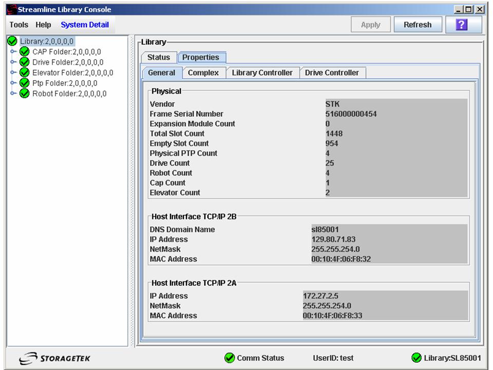
Figure D-3 shows an SLConsole display of ports 2A and 2B, including IP addresses.
Two SL8500 Network Connections - One Mainframe IP Address
To establish one host IP route from the HSC to two routes to the SL8500, use the process described in this section. To configure the SL8500 dual TCP/IP feature, refer to the StreamLine SL8500 Modular Library System Dual TCP/IP Feature document.
Figure D-4 shows dual IP (one host IP) with two SL8500 network connections.
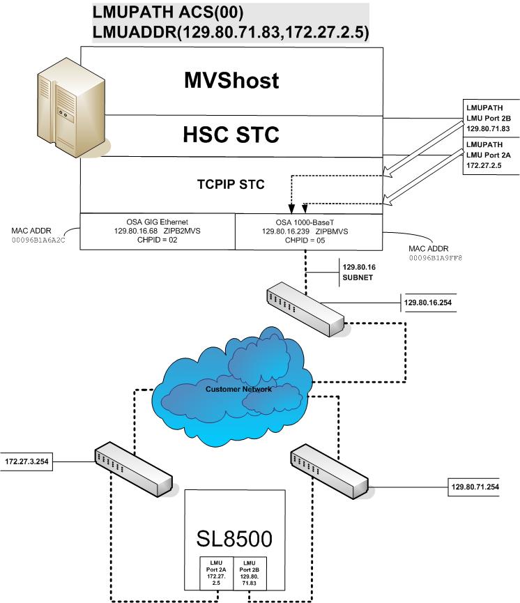
-
Complete the Network Entries Worksheet (see Table D-2 for a sample) for each set of routes to the SL8500. The worksheet can be found in the StreamLine SL8500 Modular Library System Dual TCP/IP Feature document.
-
Define two dedicated static routes to the SL8500 destination port (2A and 2B) IP addresses over one router.
Example:
BEGINROUTES
;     DESTINATION                 FIRSTHOP      LINKNAME       PACKETSIZE
ROUTE 129.80.16.0/24              =             &SYSNAME.MVS   MTU 1492
ROUTE 172.27.2.5 HOST             129.80.16.254 &SYSNAME.MVS   MTU 1492
ROUTE 129.80.71.83 HOST           129.80.16.254 &SYSNAME.MVS   MTU 1492
ROUTE DEFAULT                     129.80.16.254 &SYSNAME.MVS   MTU 1492

ENDROUTES
-
Define a second LMUADDR parameter for the port 2A IP address on the SL8500.
Example:
LMUPATH ACS(00) LMUADDR(129.80.71.83,172.27.2.5)
-
Enter the LMUPDEF command containing the LMUPATH statements that define the host name or IP address for each ACS.
LMUPDEF DSN(’xxx.xxx.xxx(xxx)')In the following example, LMUPDEF loads LMUPATH parameters from YOUR.DSN(MEMBER).
LMUPDEF DSN(’YOUR.DSN(MEMBER)')
-
Allow the trained SL8500 service representative to enter the network connections to the SL8500 library for either port 2A and 2B, whichever is applicable.
-
Vary the ACS offline and back online to pick up the revised LMUPATH statement that includes the second connection. This can be done one host at a time to minimize down time.
Sample Configuration - One Host IP, Two SL8500 Network Connections
Figure D-5 shows a sample dual IP (one host IP) configuration with two SL8500 network connections, followed by the statements that apply to it.
Setup Statements and Displays
The following information shows the statements and displays used in Figure D-5.
HSC LMUPDEF PARMLIB Member
OPTION TITLE('DUAL TCPIP CONNECTING TO SL85001')
LMUPATH ACS(00) LMUADDR(129.80.71.83,172.27.2.5)
TCP/IP Profile Data Set
; OSA CARD #1
DEVICE ECCQD01 MPCIPA   NONROUTER AUTORESTART
LINK   ZIPBMVS IPAQENET ECCQD01

HOME
 129.80.&IPADDR1 &SYSNAME.MVS

BEGINROUTES
;                  NETWORK MASK   FIRSTHOP      LINKNAME       PACKETSIZE
ROUTE 129.80.16.0/24              =             &SYSNAME.MVS   MTU 1492
ROUTE 172.27.2.5 HOST             129.80.16.254 &SYSNAME.MVS   MTU 1492
ROUTE 129.80.71.83 HOST           129.80.16.254 &SYSNAME.MVS   MTU 1492
ROUTE DEFAULT

ENDROUTES

INCLUDE ZIP.TCPIP.PROFILES(COMMON)

START ECCQD01
TCP/IP Console Displays
D TCPIP,,N,DEV
EZZ2500I NETSTAT CS V1R4 TCPIP 931
DEVNAME: LOOPBACK          DEVTYPE: LOOPBACK
 DEVSTATUS: READY
 LNKNAME: LOOPBACK          LNKTYPE: LOOPBACK    LNKSTATUS: READY
  NETNUM:  0   QUESIZE: 0
  BYTESIN: 2136824               BYTESOUT: 2136824
  ACTMTU:  65535
 BSD ROUTING PARAMETERS:
  MTU SIZE: 00000             METRIC: 00
  DESTADDR: 0.0.0.0           SUBNETMASK: 0.0.0.0
 MULTICAST SPECIFIC:
  MULTICAST CAPABILITY: NO
DEVNAME: ECCQD01           DEVTYPE: MPCIPA
 DEVSTATUS: READY         CFGROUTER: NON  ACTROUTER: NON
 LNKNAME: ZIPBMVS           LNKTYPE: IPAQENET    LNKSTATUS: READY
  BYTESIN: 48605838              BYTESOUT: 9790950  NETNUM:  0   QUESIZE: 0   SPEED: 0000001000
  IPBROADCASTCAPABILITY: NO
  ARPOFFLOAD: YES  ARPOFFLOADINFO: YES
  ACTMTU:  8992
  INBPERF: BALANCED
 BSD ROUTING PARAMETERS:
  MTU SIZE: 00000             METRIC: 00
  DESTADDR: 0.0.0.0           SUBNETMASK: 255.255.255.0
 MULTICAST SPECIFIC:
  MULTICAST CAPABILITY: YES
  GROUP             REFCNT
  -----             ------
2 OF 2 RECORDS DISPLAYED

D TCPIP,,N,ROUTE
EZZ2500I NETSTAT CS V1R4 TCPIP 933
DESTINATION      GATEWAY          FLAGS     REFCNT  INTERFACE
DEFAULT          129.80.16.254    UGS       000001  ZIPBMVS
127.0.0.1        0.0.0.0          UH        000004  LOOPBACK
129.80.16.0      0.0.0.0          US        000000  ZIPBMVS
129.80.16.239    0.0.0.0          UH        000000  ZIPBMVS
129.80.71.83     129.80.16.254    UGHS      000001  ZIPBMVS
172.27.2.5       129.80.16.254    UGHS      000001  ZIPBMVS
6 OF 6 RECORDS DISPLAYED

D TCPIP,,N,HOME
EZZ2500I NETSTAT CS V1R4 TCPIP 935
HOME ADDRESS LIST:
ADDRESS          LINK             FLG
129.80.16.239    ZIPBMVS          P
127.0.0.1        LOOPBACK
2 OF 2 RECORDS DISPLAYED
HSC Display Showing SL8500 Connection
D ACS
SLS0000I D ACS
SLS1000I ACS 00 STATUS: CONNECTED 942
ACTIVE QUEUE ELEMENTS                  1
COMPATIBILITY LEVELS: HSC=13, LMU=13
DUAL LMU NOT CONFIGURED
IP ADDR  129.80.71.83 ONLINE
IP ADDR  172.27.2.5 ONLINE
SCRATCH VOLUMES AVAILABLE......      210
FREE CELLS AVAILABLE...........     2007
Figure D-6 shows an SLConsole display of ports 2A and 2B, including IP addresses.
Multiple SL8500 Library Connections
This section discusses the following:
Connecting to Multiple SL8500 Libraries in an ACS
When SL8500 3.9x or higher firmware is installed, the HSC can connect to more than one SL8500 in an ACS (library complex).
The HSC supports up to four connections to an ACS. Some possible connections are:
-
four connections to four SL8500s
-
two connections to each of two SL8500s
-
two connections to one SL8500 and two connections to two other SL8500s.
When the HSC establishes two connections to one SL8500, the HSC provides dual TCP/IP or multiple TCP/IP connectivity. Refer to the "TCP/IP Communications - Important Considerations" discussion for more information.
Note:
-
To optimize library performance and minimize inter-library communication among SL8500s, connect to the libraries with the most activity. The HSC distributes communications to the libraries evenly.
-
LMUPATH control statements are used to define network LMU attachments.
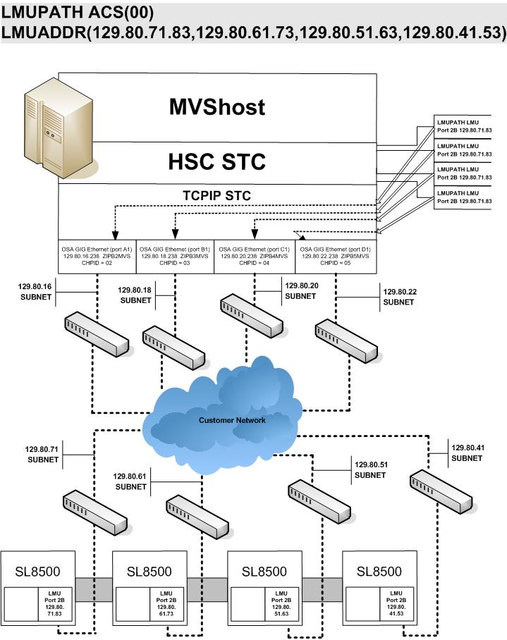
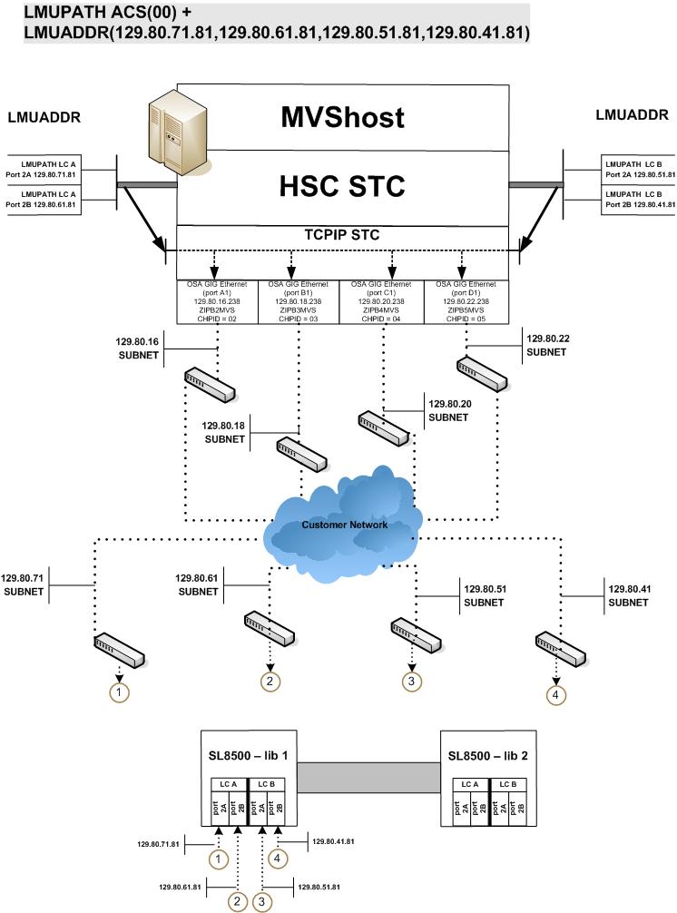
The following example shows multiple LMUADDR parameters consisting of four IP addresses. In this case, the first, second, third, and fourth IP addresses indicate a TCP/IP connection to each of four separate SL8500 libraries connected in ACS 00:
LMUPATH ACS(00)+
LMUADDR(123.456.789.012,123.456.789.013,123.456.789.014,123.456.789.015)
Sample Configuration - Four SL8500 Network Connections, Four Mainframe IP Addresses
Figure D-7 shows a sample of a four IP (four host IPs) configuration with four SL8500 network connections. This configuration applies to SL8500 3.x or higher firmware.
Powering Down the SL8500 - HSC Requirements
Prior to powering down the SL8500, the HSC requires that the following procedure must be followed:
-
Vary the drives offline at the MVS host level.
-
Modify the LSM(s) offline (see the MODify Command in the ELS Command, Control Statement, and Utility Reference).
For specific information about powering off the SL8500, refer to the SL8500 User's Guide.
Multiple TCP/IP Redundant Electronics
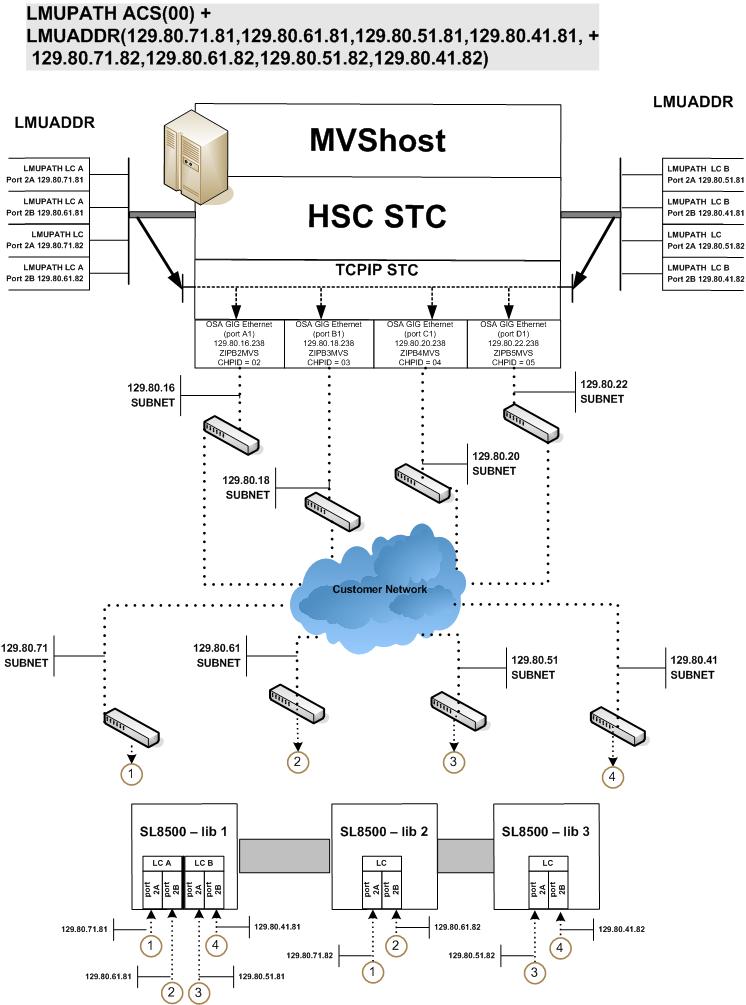
The LMUPATH control statement allows users to define network Library Controller attachments. In a Multiple TCP/IP redundant electronics environment for an SL8500 complex, specify up to 32 network connections using the LMUADDR parameter. When specified, HSC automatically adjusts when Redundant Electronics is installed.
Note:
Vary the ACS offline, updating the LMUPDEF file to accommodate redundant electronics, read the new LMUPDEF file, and vary the ACS back online to pick up the revised LMUPATH statement that includes the added connections.Sample Configuration #1 - One SL8500 Network Single Redundant Pair Connections, Four Mainframe IP Addresses
Figure D-8 shows a sample four IP (four host IPs) configuration with one single redundant pair SL8500 network connections. This configuration applies to SL8500 6.0 or higher firmware.
Sample Configuration #2 - One SL8500 Network Dual Redundant Pair Connections, Four Mainframe IP Addresses
Figure D-9 shows a sample four IP (four host IPs) configuration with one dual redundant pair SL8500 network connections. This configuration applies to SL8500 6.0 or higher firmware.
Sample Configuration #3 - One SL8500 Network Dual Redundant Pair and 2 Dual TCP/IP Connections, Four Mainframe IP Addresses
Figure D-10 shows a sample four IP (four host IPs) configuration with one dual redundant pair SL8500 and two dual TCP/IP network connections. This configuration applies to SL8500 6.0 or higher firmware.
Troubleshooting Library Connectivity Problems
This section covers procedures on helping you to provide important data to Oracle support when Library connectivity problems occur.
Basic Tracing
The following procedure tells how to produce diagnostic data for basic SL3000/SL8500 host connectivity problems.
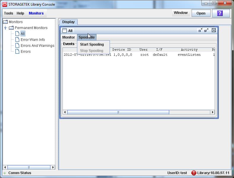
-
Using the SLConsole, start a monitor trace (select All) and start spooling to an output file as shown in the example in Figure D-11.
-
Update the HSC PARMLIB member (in bold) to add LMU tracing on as shown in the example.
CDSDEF DSN1(HSC1.PRIM),DSN2(HSC1.BKUP),DSN3(HSC1.STDBY)
MGMTDEF DSN(HSC.PARMS)COMMP METH VTAMFEAT VSM(ADVMGMT)
CAPP 9,01:00:00,AUTO
MNTD AUTOCLN(ON) EJCTAUTO(ON)
/*   turn LMU trace on      */
TR LMU
-
Start GTF to trace the HSC job as shown in the JCL example below.
//GTFTEST PROC MEMBER=GTFTST
//IEFPROC EXEC PGM=AHLGTF,PARM='MODE=EXT,DEBUG=NO,TIME=YES',
//           REGION=2880K,ACCT=505341SPKC
//IEFRDER DD   DSNAME=GTF.OUTPUT,DISP=SHR /* output trace file */
//SYSLIB  DD   DSNAME=TEST.PARMLIB(&MEMBER),DISP=SHR
Or, use a GTF SYSLIB member as shown in the following example.
TRACE=USR,JOBNAMEP
JOBNAME=(HSCT*) /* HSCT* = HSC jobname prefix (jobname example: HSCT1234) */
END
-
After a problem occurs:
-
Stop GTF.
-
Stop the spooling in the monitor trace.
-
Stop HSC.
-
-
Send to the monitor trace, GTF output files, and HSC log to StorageTek/Oracle support.
Packet Tracing
A packet trace, which traces the actual data packets that are being transferred across the line, can be helpful when trying to determine if data is actually being sent across properly. The following procedure tells how to run a packet trace.
-
Create an external writer proc in SYS1.PROCLIB(CTTCP) as shown in the following example.
//CTTCP   PROC
//CTTCP    EXEC PGM=ITTTRCWR
//TRCOUT01 DD DSN=Your_data_set,UNIT=SYSDA,
//         SPACE=(CYL,(100),,CONTIG),DISP=(NEW,CATLG)
-
Enter the following MVS commands:
TRACE CT,WTRSTART=CTTCP
TRACE CT,ON,COMP=SYSTCPDA,SUB=(your TCP/IP started task name)
R n,WTR=CTTCP,END
D TRACE,COMP=SYSTCPDA,SUB=(your TCP/IP started task name)
Note:
This will verify that trace was started successfully.V TCPIP,your TCP/IP started task name,PKT,ON,IP=xx.xx.xx.xx
Where xx.xx.xx.xx is the IP address you want to trace.
-
Run the trace until the error occurs.
-
Enter the following MVS commands:
V TCPIP,your TCP/IP started task name,PKT,OFF
TRACE CT,ON,COMP=SYSTCPDA,SUB=(your TCP/IP started task name)
R n,WTR=DISCONNECT,END
TRACE CT,OFF,COMP=SYSTCPDA,SUB=(your TCP/IP started task name)
TRACE CT,WTRSTOP=CTTCP,FLUSH
-
To format the trace, use IPCS and the following command:
CTRACE COMP(SYSTCPDA) FULL
Or use IPCS menu option 2, Option 7, Option 1, Option D and then enter component name SYSTCPDA and report type FULL.