I VSM5 ESCON/FICON Configurations
Table I-1 summarizes the supported VCF (FICON) and ICE (ESCON) card configurations for VSM5. VSM5 ESCON support requires microcode level D02.07.00.00 or H01.07.00.00.
Table I-1 Supported Card Configurations for VSM4 FICON Front-End plus Back-End Connectivity
| VCF Cards | FICON Ports | ICE Cards | ESCON Ports | Total Ports | Total Logical Paths (16 per ICE Port, 64 per VCF Port) |
|---|---|---|---|---|---|
|
0 |
0 |
8 |
32 |
32 |
512 |
|
4 |
8 |
4 |
16 |
24 |
768 |
VSM5 ICE/VCF Card Options
VSM5 supports the following ICE/VCF card options:
-
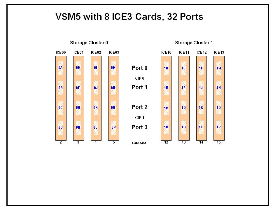
Figure I-1 shows a VSM5 with 8 ICE cards.
-
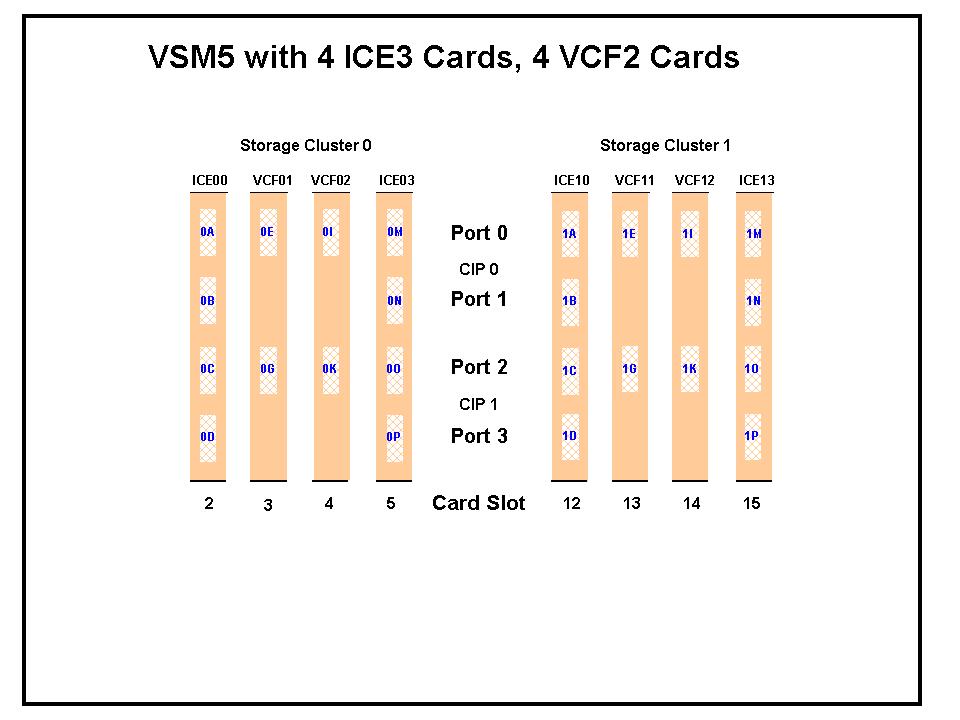
Figure I-2 shows a VSM5 with 4 ICE cards, 4 VCF cards.
-
Figure I-2, the VCF cards must go in: Slots 3, 4, 13, and 14 in a four-VCF card configuration.
-
FICON ports are controlled by a FICON Interface processor (FIP), ESCON ports are controlled by a CIP. Regardless of the card configuration, there can be only a total of 14 Nearlink FIPs and/or CIPs.
Note:
With microcode level D02.06.00.00 or higher, multiple Nearlink device connections through a FICON or ESCON switch or Director on the same port now allow:-
Up to a total of 16 simultaneous NearLink I/O transfers, which can be spread across multiple targets on as many as 14 NearLink ports.
-
Up to a total of 2 simultaneous NearLink I/O transfers are allowed per port.
-
-
All FICON ports can be configured as either a Host port or Nearlink (RTD/CLINK origination) port. All ESCON ports continue to be configurable as host or Nearlink ports in pairs on a per CIP basis.
-
As shown in Figure I-1 and Figure I-2, the ports are shown with their channel interface identifiers. These channel interface identifiers are the values that are required for the CHANIF values that you code for the CONFIG utility. Each value is two characters in length and has a value from 0A to 1O. The first digit is the VTSS cluster ID (valid values are 0 or 1). The second digit is the group or adapter ID (valid values are A to P).
Each FICON port can attach to four RTDs, or two CLINKs, or an RTD/CLINK combination through a FICON director or supported switch (in FICON mode). Note that, as shown in these figures, for RTDs only, each FICON port has two CHANIF values only if the port is connected to a FICON director which is then connected to two RTDs. Nearlink RTD connections that are paired through a FICON switch or director on the same port dynamically alternate between both RTDs for atomic operations such as mount, migrate VTV, recall VTV, and so forth.
-
Each ICE card contains two pairs of ESCON ports. Each pair is controlled by its own Channel Interface Processor (CIP). Each CIP switches between the two ports, so that only one port can transfer data at a time, which emulates a FICON port attached to a director attached to RTDs.
-
Each host FICON channel supports 64 logical paths (times 16 logical units). However, in HCD:
-
From a single MVS host, you can only define 8 channels (CHPIDs) running to a single control unit (single VSM5).
-
You use the CNTLUNIT statement to define each VSM5 as 16 3490 control unit images.
-
You use the IODEVICE statement to define the 16 VTDs that are associated with each 3490 control unit image.
-
-
For a VSM5, each ESCON CIP or FICON FIP can operate with only one of two modes, which is set at the VTSS DOP:
-
Host Mode. In Host Mode, ports can connect to the host CPU channels, including using Director(s) or channel extenders. A port in Host Mode can also serve as a CLINK terminator.
Also note that for ESCON ports, you can have two physical paths from the same LPAR to the same CIP, as long as the two physical paths address different (not overlapping) logical control units. For example, a single host LPAR can address logical control units 0-7 on one CIP port, and 8-F on the other CIP port of the same CIP.
-
Nearlink Mode. In Nearlink Mode, ports can connect to an RTD. A port in Nearlink Mode can also serve as a CLINK originator.
Caution:
In bi-directional clustering, each CLINK must be attached to the same Storage Cluster on each VTSS, which is a requirement. Failure to configure in this manner can produce Replicate, Channel, and Communication errors.
-
For both FICON and ESCON, Table I-2 shows Best Practices for optimizing port operations.
Table I-2 Optimizing VSM5 FICON/ESCON Port Operations
| Configuration - Two ESCON Ports on a CIP (ICE) or FICON port attached to a FICON Director (VCF) | Best Practices |
|---|---|
|
Multiple CLINKs (up to 4) |
Attach a maximum of 2 because each port allows two active operations. Note, however, that these operations share the bandwidth of the port. |
|
CLINK and RTD combinations |
An advantage if you attach one CLINK originator/one RTD per director, because both can be active. |
|
Up to 4 RTDs |
An advantage for the following:
|
VSM5 Configuration Example: 8 ICE Cards, 16 Host Ports, 16 RTD Ports
Figure I-3 shows CONFIG channel interface identifiers of 16 for hosts, 16 for RTDs for a VSM5.
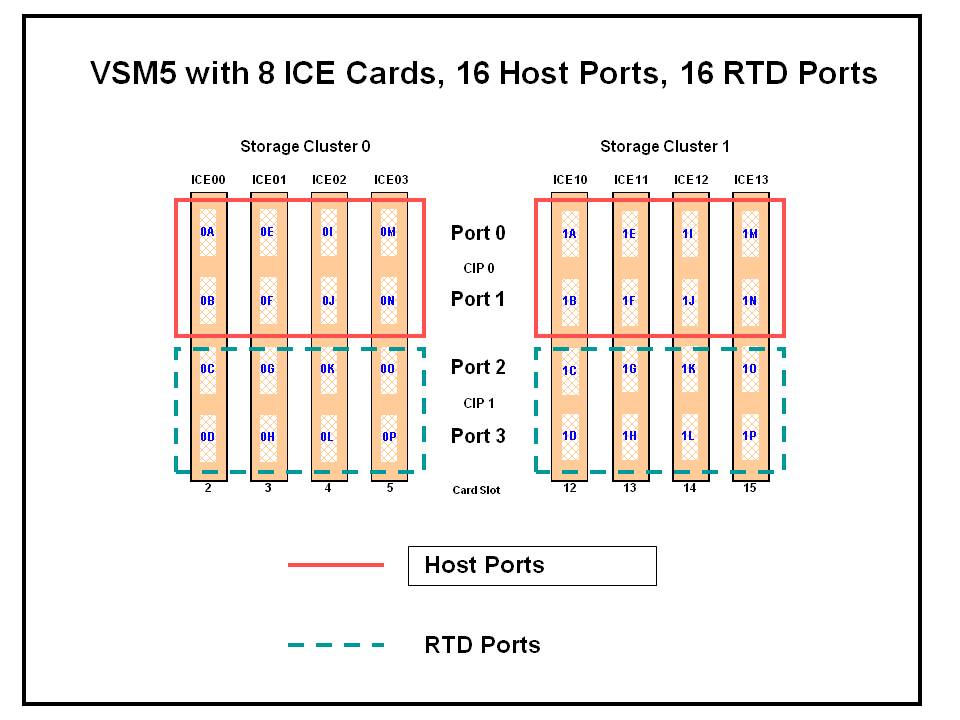
CONFIG Example for VSM5 with 16 Host Ports, 16 RTD Ports
The following example shows CONFIG JCL to define the VSM5 configuration shown in Figure I-3.
//CREATECF EXEC PGM=SLUADMIN,PARM='MIXED'
//STEPLIB DD DSN=hlq.SEALINK,DISP=SHR
//SLSCNTL DD DSN=hlq.DBASEPRM,DISP=SHR
//SLSCNTL2 DD DSN=hlq.DBASESEC,DISP=SHR
//SLSSTBY DD DSN=hlq.DBASETBY,DISP=SHR
//SLSPRINT DD   SYSOUT=*
//SLSIN DD   *
 CONFIG
 GLOBAL MAXVTV=32000 MVCFREE=40
 RECLAIM THRESHLD=70 MAXMVC=40  START=35
VTSS NAME=VSM501 LOW=70 HIGH=80 MAXMIG=8 RETAIN=5
 RTD  NAME=VSM52A00 DEVNO=2A00 CHANIF=0C
 RTD  NAME=VSM52A01 DEVNO=2A01 CHANIF=0D
 RTD  NAME=VSM52A02 DEVNO=2A02 CHANIF=0G
 RTD  NAME=VSM52A03 DEVNO=2A03 CHANIF=0H
 RTD  NAME=VSM52A04 DEVNO=2A04 CHANIF=0K
 RTD  NAME=VSM52A05 DEVNO=2A05 CHANIF=0L
 RTD  NAME=VSM52A06 DEVNO=2A06 CHANIF=0O
 RTD  NAME=VSM52A07 DEVNO=2A07 CHANIF=0P
 RTD  NAME=VSM52A08 DEVNO=2A08 CHANIF=1C
 RTD  NAME=VSM52A09 DEVNO=2A09 CHANIF=1D
 RTD  NAME=VSM52A0A DEVNO=2A0A CHANIF=1G
 RTD  NAME=VSM52A0B DEVNO=2A0B CHANIF=1H
 RTD  NAME=VSM52A0C DEVNO=2A0C CHANIF=1K
 RTD  NAME=VSM52A0D DEVNO=2A0D CHANIF=1L
 RTD  NAME=VSM52A0E DEVNO=2A0E CHANIF=1O
 RTD  NAME=VSM52A0F DEVNO=2A0F CHANIF=1P
 VTD LOW=9900 HIGH=99FF
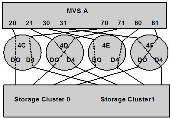
IOCP Example for Single MVS Host Connected to a VSM5 Using ESCON Directors
Figure I-4 shows a configuration diagram for a single MVS host connected to a VSM5 through ESCON Directors, and the example that follows it shows IOCP statements for this configuration. Note that:
-
From MVSA, you define 8 CHPIDs, with each path switched in the ESCON Director, for a total of 8 channels running to the VSM5.
-
You code 16 CNTLUNIT statements to define the VSM5 as 16 3490 images.
-
You code IODEVICE statement to define the 16 VTDs that are associated with each 3490 image.
ESCD4C CHPID PATH=(20,70),TYPE=CNC,SWITCH=4C
ESCD4D CHPID PATH=(21,71),TYPE=CNC,SWITCH=4D
ESCD4E CHPID PATH=(30,80),TYPE=CNC,SWITCH=4E
ESCD4F CHPID PATH=(31,81),TYPE=CNC,SWITCH=4F

CU1 CNTLUNIT CUNUMBR=001,
       PATH=(20,21,30,31,70,71,80,81),
       LINK=(D0,D4,D0,D4,D4,D0,D4,D0),
       UNIT=3490,CUADD=0,
       UNITADD=((00,16))

STRING1 IODEVICE ADDRESS=(0500,16),
       CUNUMBER=(001),
       UNIT=3490,
       UNITADD=00,STADET=Y

CU2 CNTLUNIT CUNUMBR=002,
       PATH=(20,21,30,31,70,71,80,81),
       LINK=(D0,D4,D0,D4,D4,D0,D4,D0),
       UNIT=3490,CUADD=1,
       UNITADD=((00,16))

STRING2 IODEVICE ADDRESS=(0510,16),
       CUNUMBER=(002),
       UNIT=3490,
       UNITADD=00,STADET=Y
       .
       .
       .
CU15 CNTLUNIT CUNUMBR=015,
       PATH=(20,21,30,31,70,71,80,81),
       LINK=(D0,D4,D0,D4,D4,D0,D4,D0),
       UNIT=3490,CUADD=E,
       UNITADD=((00,16))

STRING15 IODEVICE ADDRESS=(05E0,16),
       CUNUMBER=(015),
       UNIT=3490,
       UNITADD=00,STADET=Y

CU16 CNTLUNIT CUNUMBR=016,
       PATH=(20,21,30,31,70,71,80,81),
       LINK=(D0,D4,D0,D4,D4,D0,D4,D0),
       UNIT=3490,CUADD=F,
       UNITADD=((00,16))

STRING16 IODEVICE ADDRESS=(05F0,16),
       CUNUMBER=(016),
       UNIT=3490,
       UNITADD=00,STADET=Y