A Clustered VTSS Examples
"Using Clustered VTSS Configurations" provides the basics of VTSS Clustering and this appendix provides the following Clustering examples:
Uni-Directional Clustered VTSS
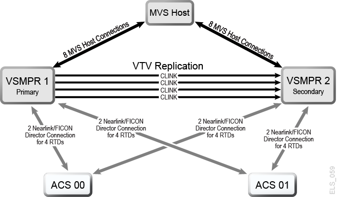
Figure A-1 shows an example of a Uni-Directional Clustered VTSS Dual ACS system. Note that in this example, FICON ports provide the CLINK connections. In this example, there is only one MVS host, but it is putting out a lot of critical data that you must protect using two brand new VSM4s that you have just purchased.
VTSS1 is the Primary VTSS, and it is connected to the Secondary (VTSS2) using Cluster Links (CLINKs). If the Management Class for a VTV specifies replication, when the VTV arrives in VTSS1, it is replicated (copied) to VTSS2, and also immediately migrated (with KEEP).
As a result, you have increased data availability (there is a copy of the VTV in each VTSS in case one fails) and data protection (the VTV is also on square tape in case both VTSSs go offline). Clustered VTSS is a great solution, therefore, for business continuity and business resumption.
Figure A-1 Dual ACS Uni-Directional Clustered VTSS Configuration
Description of ''Figure A-1 Dual ACS Uni-Directional Clustered VTSS Configuration''
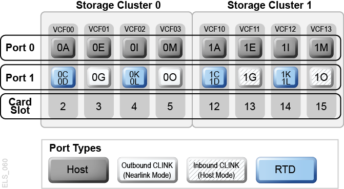
Now take a look at the hardware for this Clustered configuration. Figure A-2 shows CONFIG channel interface identifiers for a VSM4 with 8 VCF cards. In this configuration, you have allocated:
-
8 Host ports
-
4 ports for RTDs. The RTD ports are all connected to FICON directors, each of which is attached to RTDs, so the
CHANIFidentifiers for both RTDs are shown on each port. This allows Back-End connection to 8 RTDs, although only one RTD per port/Director can be active at a time. -
4 ports for CLINK connections to form a Uni-Directional VTSS Cluster, and 8 ports to host connections. To form the clustered VTSS, there are two VSM4s (VTSS1 and VTSS2) configured identically as shown in Figure A-2.
Figure A-2 VSM4 with 8 VCF Cards, 8 Host Ports, FICON Directors for 8 RTDs, 4 CLINK Ports
Description of ''Figure A-2 VSM4 with 8 VCF Cards, 8 Host Ports, FICON Directors for 8 RTDs, 4 CLINK Ports''
You have now seen what an example Uni-Directional Cluster looks like, and you have seen the VCF card port configurations required. Now look at "Configuring and Managing a Uni-Directional Clustered VTSS System."
Configuring and Managing a Uni-Directional Clustered VTSS System
To configure and manage the Uni-Directional Clustered system shown in Figure 6-1, do the following:
-
Ensure that your system has the Clustered VTSS requirements.
-
Use
CONFIGto createCLUSTERandCLINKstatements to define the VTSS Cluster and its connections.The following example shows CONFIG JCL to define a Uni-Directional Cluster of two VSM4s (VTSS1 and VTSS2) as shown in Figure 6-1.
Note that:
-
The CLUSTER statement defines the Cluster as consisting of VTSS1 and VTSS2.
-
There are CLINK statements using the sending (Nearlink Mode) ports of only VTSS1 to enable the Cluster as Uni-Directional, where VTSS1 is the Primary and VTSS2 is the Secondary.
//CREATECFG EXEC PGM=SWSADMIN,PARM='MIXED'
//STEPLIB  DD DSN=hlq.SLSLINK,DISP=SHR
//SLSCNTL  DD DSN=FEDB.VSMLMULT.DBASEPRM,DISP=SHR
//SLSCNTL2 DD DSN=FEDB.VSMLMULT.DBASESEC,DISP=SHR
//SLSSTBY  DD DSN=FEDB.VSMLMULT.DBASETBY,DISP=SHR
//CFG22202 DD DSN=FEDB.VSMLMULT.CFG22202,DISP=SHR
//SLSPRINT DD   SYSOUT=*
//SLSIN    DD   *
CONFIG RESET CDSLEVEL(V62ABOVE)
GLOBAL MAXVTV=65000 MVCFREE=60 VTVATTR=SCRATCH RECALWER=YES
LOCKSTR=STK_VTCS_LOCKS VTVPAGE=LARGE
RECLAIM THRESHLD=70 MAXMVC=30 START=40 CONMVC=5
VTVVOL LOW=905000 HIGH=999999 SCRATCH
VTVVOL LOW=C00000 HIGH=C25000 SCRATCH
VTVVOL LOW=RMM000 HIGH=RMM020 SCRATCH
MVCVOL LOW=N25980 HIGH=N25989
MVCVOL LOW=N35000 HIGH=N35999
VTSS NAME=VTSS1 LOW=70 HIGH=80 MAXMIG=8 MINMIG=4 RETAIN=5
RTD  NAME=PR11A00 DEVNO=1A00 CHANIF=0C
RTD  NAME=PR11A01 DEVNO=1A01 CHANIF=0D
RTD  NAME=PR11A02 DEVNO=1A02 CHANIF=0K
RTD  NAME=PR11A03 DEVNO=1A03 CHANIF=0L
RTD  NAME=PR12A08 DEVNO=2A08 CHANIF=1C
RTD  NAME=PR12A09 DEVNO=2A09 CHANIF=1D
RTD  NAME=PR12A0A DEVNO=2A0A CHANIF=1K
RTD  NAME=PR12A0B DEVNO=2A0B CHANIF=1L
VTD LOW=9900 HIGH=99FF
VTSS NAME=VTSS2 LOW=70 HIGH=80 MAXMIG=8 MINMIG=4 RETAIN=5
RTD  NAME=PR23A00 DEVNO=3A00 CHANIF=0C
RTD  NAME=PR23A01 DEVNO=3A01 CHANIF=0D
RTD  NAME=PR23A02 DEVNO=3A02 CHANIF=0K
RTD  NAME=PR23A03 DEVNO=3A03 CHANIF=0L
RTD  NAME=PR24A08 DEVNO=4A08 CHANIF=1C
RTD  NAME=PR24A09 DEVNO=4A09 CHANIF=1D
RTD  NAME=PR24A0A DEVNO=4A0A CHANIF=1K
RTD  NAME=PR24A0B DEVNO=4A0B CHANIF=1L
VTD LOW=9900 HIGH=99FF
CLUSTER NAME=CLUSTER1 VTSSs(VTSS1,VTSS2)
CLINK VTSS=VTSS1 CHANIF=0G
CLINK VTSS=VTSS1 CHANIF=0O
CLINK VTSS=VTSS1 CHANIF=1G
CLINK VTSS=VTSS1 CHANIF=1O
-
-
Specify the Conditional Replication setting on the
CONFIG GLOBALstatement.CONFIG GLOBAL REPLICAT=CHANGED
In this example,
CONFIG GLOBAL REPLICAT=CHANGEDspecifies:-
Replicate VTVs only if the VTV is updated and an identical copy does not exist in the Secondary.
-
Using the
MIGPOLparameter, migrate VTVs duplexed to ACSs 00 and 01 by Storage Classes you create in Step 5.To unconditionally replicate VTVs, specify
CONFIG GLOBAL REPLICAT=ALWAYS.
-
-
Create a Management Class that specifies VTV replication and two Storage Classes to migrate (duplexed) the replicated VTVs.
MGMT NAME(VSMREPL) REPLICAT(YES) MIGPOL(REPLSTR1,REPLSTR2)
Note:
-
Note the interaction between
GLOBAL REPLICAT, which specifies when the replication can occur, andMGMTclas REPLICAT(YES), which says when theGLOBAL REPLICATcondition says it is time, go ahead and replicate. -
The Management Class
VSMREPLdoes not specify an immediate migrate policy. VTV replication automatically enforces immediate migrate. The VTVs in this Management Class is added to the immediate migration queue on VTSS once the replication has completed. Note that duplexing is not a requirement for replicate VTVs. For more information, see "How Clustered VTSS Configurations Work."
-
-
Create the Storage Classes for the MVCs that contain the replicated, migrated VTVs.
STOR NAME(REPLSTR1) ACS(00) MEDIA(STK1R) MIRATE(RECEIVER)
STOR NAME(REPLSTR2) ACS(01) MEDIA(STK1R) MIGRATE(RECEIVER)
In this example, the
STORclasstatement defines Storage Classes REPLSTR1 and REPLSTR2 referenced in theMIGPOLparameter in Step 4. Also note that theMIGRATEparameters on the Storage Classes specify that the VTSS receiving the replicated VTV, in this case VTSS2, the Secondary, does the migration to both ACSs. This is a way of ensuring that the Secondary functions as the migrate engine. -
Load the
MGMTclasandSTORclascontrol statements with theMGMTDEFcommand.MGMTDEF DSN(hsc.parms)
-
Create a
TAPEREQstatement to route the critical data to VSM and assign Management Class VSMREPL to the data.TAPEREQ DSN(*.PAYROLL.**) MEDIA(VIRTUAL) MGMT(VSMREPL)
In this example, the
TAPEREQstatement specifies:-
Route data sets with HLQ mask *.PAYROLL.** to VSM.
-
Assign Management Class VSMREPL that you created in Step 4.
Caution:
To replicate VTVs, both VTSS1 and VTSS2 must be varied online to VTCS so that VTCS can send control commands to both VTSSs. See "How Clustered VTSS Configurations Work" for more information.
You can also use esoteric substitution through the SMC
TAPEREQstatement or SMC DFSMS ACS routines to route replication jobs to VSM. For more information, see SMC Configuration and Administration Guide. -
-
Check your HSC PARMLIB options to ensure that subtype 28 records are enabled.
If enabled, VTSS clustering writes a subtype 28 record for each replication performed.
Bi-Directional Clustered VTSS
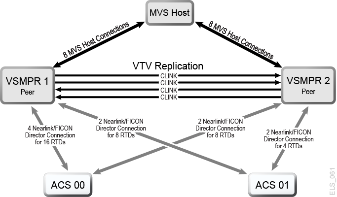
Figure A-3 shows an example of a Bi-Directional Clustered VTSS Dual ACS system. Note that in this example, FICON ports provide the CLINK connections.
This system is very similar to the uni-directional example, but goes one step further: There are two MVS hosts sharing a CDS, and everything in the picture is cross-connected. These sites mirror each other for the best data availability and protection. To make it bi-directional, you must configure the two VTSSs as peers using the CLINK statements.
Figure A-3 Dual ACS Bi-Directional Clustered VTSS Configuration
Description of ''Figure A-3 Dual ACS Bi-Directional Clustered VTSS Configuration''
Note:
-
Bi-Directional Clustering requires VTCS 6.1 and above. You cannot configure a Bi-Directional Cluster at releases lower than VTCS 6.1.
-
This configuration is shown with the feature that enables up to a total of 16 simultaneous NearLink I/O transfers. These can be spread across multiple targets on as many as 14 NearLink ports, with up to a total of 2 simultaneous NearLink I/O transfers per port. This feature requires VTSS microcode D02.06.00.00 or higher.
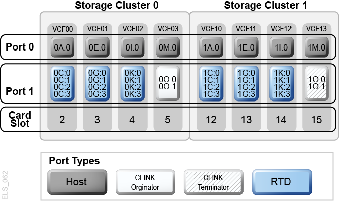
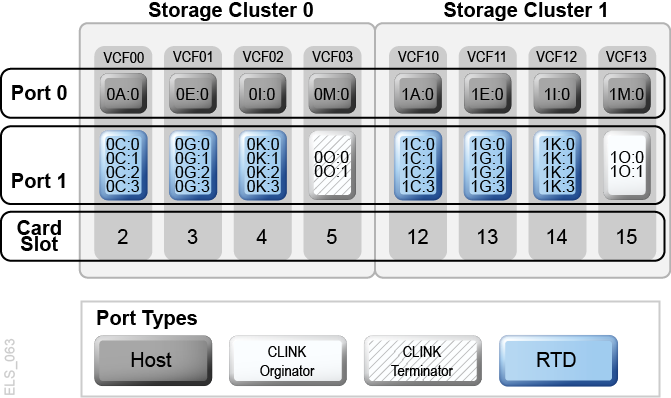
Figure A-4 shows CONFIG channel interface identifiers for VSMPR1 shown in Figure A-3. In this configuration, you have allocated:
-
8 Host ports
-
6 ports for RTDs. The RTD ports are all connected to FICON directors, each of which is attached to 4 RTDs, so the CHANIF identifiers for all 4 RTDs are shown on each port. This allows Back-End connection to 24 RTDs for ACS00, although only one RTD per port/Director can be active at a time.
-
4 ports using FICON directors. Two are Nearlink for the originator, two are host mode for the terminator for CLINK connections to form a Bi-Directional VTSS Cluster.
Figure A-4 VSMPR1 - VSM5 with 8 VCF Cards, 8 Host Ports, FICON Directors for 24 RTDs, 4 CLINKs
Description of ''Figure A-4 VSMPR1 - VSM5 with 8 VCF Cards, 8 Host Ports, FICON Directors for 24 RTDs, 4 CLINKs''
Figure A-5 shows CONFIG channel interface identifiers for a VSMPR1, a VSM5 in a Bi-directional Cluster with 8 VCF cards and the Maximum 32 RTDs feature enabled. In this configuration, you have allocated:
-
8 Host ports
-
6 ports for RTDs. The RTD ports are all connected to FICON directors, each of which is attached to 4 RTDs, so the
CHANIFidentifiers for all 4 RTDs are shown on each port. This allows Back-End connection to 24 RTDs, although only one RTD per port/Director can be active at a time.Figure A-5 VSMPR2 - VSM5 with 8 VCF Cards, 8 Host Ports, FICON Directors for 24 RTDs, 4 CLINKs
Description of ''Figure A-5 VSMPR2 - VSM5 with 8 VCF Cards, 8 Host Ports, FICON Directors for 24 RTDs, 4 CLINKs''
-
4 ports using FICON directors. Two are Nearlink for the originator, two are host mode for the terminator for CLINK connections to form a Bi-Directional VTSS Cluster.
Caution:
As shown in Figure 6-3, each CLINK must be attached to the same Storage Cluster on each VTSS, which is a requirement. Failure to configure in this manner can produce Replicate, Channel, and Communication errors!So as shown, the Nearlink ports (CLINK originators) on VSMPR1 are on Storage Cluster 0 and the Host ports (CLINK terminators) on VSMPR2 are also on Storage Cluster 0. The same is true for the CLINK connections for data flowing in the other direction; they are both on Storage Cluster 1.
Configuring and Managing a Bi-Directional Clustered System
To configure and manage the Bi-Directional Clustered system shown in Figure A-3, do the following:
-
Ensure that your system has the Clustered VTSS requirements described in Installing ELS.
-
Use
CONFIGto createCLUSTERandCLINKstatements to define the VTSS Cluster and its connections.The following example shows CONFIG JCL to define a Bi-Directional Cluster of two VSM4s (VSMPR1 and VSMPR2) as shown in Figure A-3.
-
Note that the
CLUSTERstatement defines the Cluster as consisting of VSMPR1 and VSMPR2. -
There are
CLINKstatements using the sending (Nearlink Mode) ports of both VTSSs to enable the Cluster as Bi-Directional and they connect using the same Storage Cluster on each VTSS for the sending and receiving ports of each CLINK.//CREATECF EXEC PGM=SWSADMIN,PARM='MIXED' //STEPLIB DD DSN=hlq.SLSLINK,DISP=SHR //SLSCNTL DD DSN=FEDB.VSMLMULT.DBASEPRM,DISP=SHR //SLSCNTL2 DD DSN=FEDB.VSMLMULT.DBASESEC,DISP=SHR //SLSSTBY DD DSN=FEDB.VSMLMULT.DBASETBY,DISP=SHR //SLSPRINT DD SYSOUT=* //SLSIN DD * CONFIG RESET CDSLEVEL(V61ABOVE) GLOBAL MAXVTV=32000 MVCFREE=40 VTVATTR=SCRATCH RECALWER=YES LOCKSTR=VTCS_LOCKS REPLICAT=ALWAYS VTVPAGE=LARGE SYNCHREP=YES MAXRTDS=32 RECLAIMTHRESHLD=70 MAXMVC=40 START=35 RECLAIMTHRESHLD=70 MAXMVC=40 START=35 VTVVOL LOW=905000 HIGH=999999 SCRATCH VTVVOL LOW=C00000 HIGH=C25000 SCRATCH VTVVOL LOW=RMM000 HIGH=RMM020 SCRATCH MVCVOL LOW=N25980 HIGH=N25989 MVCVOL LOW=N35000 HIGH=N35999 VTSS NAME=VSMPR1 LOW=70 HIGH=80 MAXMIG=8 MINMIG=4 RETAIN=5 RTD NAME=VPR12A00 DEVNO=2A00 CHANIF=0C:0 RTD NAME=VPR12A01 DEVNO=2A01 CHANIF=0C:1 RTD NAME=VPR12A02 DEVNO=2A02 CHANIF=0C:2 RTD NAME=VPR12A03 DEVNO=2A03 CHANIF=0C:3 RTD NAME=VPR12A04 DEVNO=2A04 CHANIF=0G:0 RTD NAME=VPR12A05 DEVNO=2A05 CHANIF=0G:1 RTD NAME=VPR12A06 DEVNO=2A06 CHANIF=0G:2 RTD NAME=VPR12A07 DEVNO=2A07 CHANIF=0G:3 RTD NAME=VPR12A08 DEVNO=2A08 CHANIF=0K:0 RTD NAME=VPR12A09 DEVNO=2A09 CHANIF=0K:1 RTD NAME=VPR12A0A DEVNO=2A0A CHANIF=0K:2 RTD NAME=VPR12A0B DEVNO=2A0B CHANIF=0K:3 RTD NAME=VPR13A00 DEVNO=3A00 CHANIF=1C:0 RTD NAME=VPR13A01 DEVNO=3A01 CHANIF=1C:1 RTD NAME=VPR13A02 DEVNO=3A02 CHANIF=1C:2 RTD NAME=VPR13A03 DEVNO=3A03 CHANIF=1C:3 RTD NAME=VPR13A04 DEVNO=3A04 CHANIF=1G:0 RTD NAME=VPR13A05 DEVNO=3A05 CHANIF=1G:1 RTD NAME=VPR13A06 DEVNO=3A06 CHANIF=1G:2 RTD NAME=VPR13A07 DEVNO=3A07 CHANIF=1G:3 RTD NAME=VPR13A08 DEVNO=3A08 CHANIF=1K:0 RTD NAME=VPR13A09 DEVNO=3A09 CHANIF=1K:1 RTD NAME=VPR13A0A DEVNO=3A0A CHANIF=1K:2 RTD NAME=VPR13A0B DEVNO=3A0B CHANIF=1K:3 VTD LOW=9900 HIGH=99FF VTSS NAME=VSMPR2 LOW=70 HIGH=80 MAXMIG=8 MINMIG=4 RETAIN=5 RTD NAME=VPR22B00 DEVNO=2B00 CHANIF=0C:0 RTD NAME=VPR22B01 DEVNO=2B01 CHANIF=0C:1 RTD NAME=VPR22B02 DEVNO=2B02 CHANIF=0C:2 RTD NAME=VPR22B03 DEVNO=2B03 CHANIF=0C:3 RTD NAME=VPR22B04 DEVNO=2B04 CHANIF=0G:0 RTD NAME=VPR22B05 DEVNO=2B05 CHANIF=0G:1 RTD NAME=VPR22B06 DEVNO=2B06 CHANIF=0G:2 RTD NAME=VPR22B07 DEVNO=2B07 CHANIF=0G:3 RTD NAME=VPR22B08 DEVNO=2B08 CHANIF=0K:0 RTD NAME=VPR22B09 DEVNO=2B09 CHANIF=0K:1 RTD NAME=VPR22B0A DEVNO=2B0A CHANIF=0K:2 RTD NAME=VPR22B0B DEVNO=2B0B CHANIF=0K:3 RTD NAME=VPR23B00 DEVNO=3B00 CHANIF=1C:0 RTD NAME=VPR23B01 DEVNO=3B01 CHANIF=1C:1 RTD NAME=VPR23B02 DEVNO=3B02 CHANIF=1C:2 RTD NAME=VPR23B03 DEVNO=3B03 CHANIF=1C:3 RTD NAME=VPR23B04 DEVNO=3B04 CHANIF=1G:0 RTD NAME=VPR23B05 DEVNO=3B05 CHANIF=1G:1 RTD NAME=VPR23B06 DEVNO=3B06 CHANIF=1G:2 RTD NAME=VPR23B07 DEVNO=3B07 CHANIF=1G:3 RTD NAME=VPR23B08 DEVNO=3B08 CHANIF=1K:0 RTD NAME=VPR23B09 DEVNO=3B09 CHANIF=1K:1 RTD NAME=VPR23B0A DEVNO=3B0A CHANIF=1K:2 RTD NAME=VPR23B0B DEVNO=3B0B CHANIF=1K:3 VTD LOW=9900 HIGH=99FF CLUSTER NAME=CLUSTER1 VTSSs(VSMPR1,VSMPR2) CLINK VTSS=VSMPR1 CHANIF=0O:0 CLINK VTSS=VSMPR1 CHANIF=0O:1 CLINK VTSS=VSMPR2 CHANIF=1O:0 CLINK VTSS=VSMPR2 CHANIF=1O:1
-
-
Specify the Conditional Replication setting on the
CONFIG GLOBALstatement.CONFIG GLOBAL REPLICAT=CHANGED
As with the uni-directional example, in this example, use
CONFIG GLOBAL REPLICAT=CHANGED. -
Create a Management Class that specifies VTV replication and two Storage Class to migrate (duplexed) the replicated VTVs.
MGMT NAME(VSMREPL) REPLICAT(YES) MIGPOL(REPLSTR1,REPLSTR2)
In this example, replicate VTVs only if changed and not in the other VTSS in the Cluster. Migrate duplexed to ACSs 01 and 00 by Storage Classes you will create in Step 5.
-
Create the Storage Classes for the MVCs that contain the replicated, migrated VTVs.
STOR NAME(REPLSTR1) ACS(01) MEDIA(STK1R) MIRATE(EITHER)
STOR NAME(REPLSTR2) ACS(00) MEDIA(STK1R) MIGRATE(EITHER)
In this example, the
STORclasstatement defines Storage Classes REPLSTR1 and REPLSTR2 referenced in theMIGPOLparameter in Step 4. Also note that, to optimize VTSS and RTD resources, theMIGRATEparameters on the Storage Classes allow migrates to come from either VTSS. This is a typical strategy for Bi-Directional, or Peer to Peer VTSS Clusters. -
Load the
MGMTclasandSTORclascontrol statements with theMGMTDEFcommand.MGMTDEF DSN(hsc.parms)
-
Create a
TAPEREQstatement to route the critical data to VSM and assign Management Class VSMREPL to the data.TAPEREQ DSN(*.PAYROLL.**) MEDIA(VIRTUAL) MGMT(VSMREPL)
In this example, the
TAPEREQstatement specifies:-
Route data sets with HLQ mask *.PAYROLL.** to VSM.
-
Assign Management Class VSMREPL that you enabled in Step 4.
Caution:
To replicate VTVs, both VSMPR1 and VSMPR2 must be varied online to VTCS so that VTCS can send control commands to both VTSSs. See "How Clustered VTSS Configurations Work" for more information. -
You can also use esoteric substitution using SMC
TAPEREQstatement or ELS User Exits to route replication jobs to VSM. If an esoteric is substituted that spans all VTDs in all Peer VTSSs, then VTCS can continue to correctly influence allocation if a one of the Peer VTSSs in a Cluster is taken offline. -
For SMC, a Management Class name, if it is assigned in the StorageTek DFSMS Interface, is available at allocation time. Therefore the esoteric assigned in the interface no longer needs to contain only VTSSs that are part of clusters. As long as the esoteric contains some drives located on the Primary of a full function cluster, SMC has sufficient information to direct allocation to a drive on a Primary VTSS if the Management Class specifies replication enabled.
-
-
Check your HSC PARMLIB options to ensure that subtype 28 records are enabled.
If enabled, VTSS clustering writes a subtype 28 record for each replication performed.
Extended Clustering
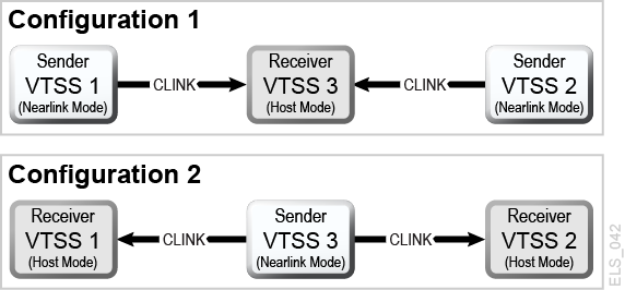
Extended Clustering (EC) allows three or more VTSSs to be connected by CLINKs within a single Tapeplex (1 CDS) configuration as shown in the example in Figure A-6.
Figure A-6 Basic Extended Cluster Configurations
Description of ''Figure A-6 Basic Extended Cluster Configurations''
Configuring and Managing a 3 VTSS Clustered System
As shown in Figure A-6, Configuration 1 shows 2 VTSSs replicating to a single "Collector" VTSS, which is the most practical configuration because a primary location with multiple VSMs can feed VTVs to a secondary location with a single collector VSM. Both Synchronous and Asynchronous replication are available to be used on each Sender VTSS. Each VTSS must have equivalent (like model) RTDs connected. As shown in the CONFIG statements for Configuration 1 that follows:
-
The
CLUSTERstatement defines all the VTSS names configured for clustering. -
The
CLINKstatement defines the Nearlink port location on the Sending VTSS and its PARTNER or destination VTSS./CREATCFG EXEC PGM=SLUADMIN,PARM='MIXED' //STEPLIB DD DSN=hlq.SEALINK,DISP=SHR //SLSCNTL DD DSN=hlq.DBASEPRM,DISP=SHR //SLSCNTL2 DD DSN=hlq.DBASESEC,DISP=SHR //SLSSTBY DD DSN=hlq.DBASETBY,DISP=SHR //SLSPRINT DD SYSOUT=* //SLSIN DD * CONFIG RESET CDSLEVEL(V62ABOVE) GLOBAL MAXVTV=65000 MVCFREE=60 VTVATTR=SCRATCH RECALWER=YES LOCKSTR=STK_VTCS_LOCKS VTVPAGE=LARGE RECLAIM THRESHLD=70 MAXMVC=30 START=40 CONMVC=5 VTSS NAME=VTSS1 LOW=70 HIGH=80 MAXMIG=8 MINMIG=4 RETAIN=5 RTD NAME=PA11A00 DEVNO=1A00 CHANIF=0C RTD NAME=PA11A01 DEVNO=1A01 CHANIF=0D RTD NAME=PA11A02 DEVNO=1A02 CHANIF=0K RTD NAME=PA11A03 DEVNO=1A03 CHANIF=0L RTD NAME=PA12A08 DEVNO=2A08 CHANIF=1C RTD NAME=PA12A09 DEVNO=2A09 CHANIF=1D RTD NAME=PA12A0A DEVNO=2A0A CHANIF=1K RTD NAME=PA12A0B DEVNO=2A0B CHANIF=1L VTD LOW=7900 HIGH=79FF VTSS NAME=VTSS2 LOW=70 HIGH=80 MAXMIG=8 MINMIG=4 RETAIN=5 RTD NAME=PA23A00 DEVNO=3A00 CHANIF=0C RTD NAME=PA23A01 DEVNO=3A01 CHANIF=0D RTD NAME=PA23A02 DEVNO=3A02 CHANIF=0K RTD NAME=PA23A03 DEVNO=3A03 CHANIF=0L RTD NAME=PA24A08 DEVNO=4A08 CHANIF=1C RTD NAME=PA24A09 DEVNO=4A09 CHANIF=1D RTD NAME=PA24A0A DEVNO=4A0A CHANIF=1K RTD NAME=PA24A0B DEVNO=4A0B CHANIF=1L VTD LOW=8900 HIGH=89FF VTSS NAME=VTSS3 LOW=70 HIGH=80 MAXMIG=8 MINMIG=4 RETAIN=5 RTD NAME=PA33A00 DEVNO=3A00 CHANIF=0C RTD NAME=PA33A01 DEVNO=3A01 CHANIF=0D RTD NAME=PA33A02 DEVNO=3A02 CHANIF=0K RTD NAME=PA33A03 DEVNO=3A03 CHANIF=0L RTD NAME=PA34A08 DEVNO=4A08 CHANIF=1C RTD NAME=PA34A09 DEVNO=4A09 CHANIF=1D RTD NAME=PA34A0A DEVNO=4A0A CHANIF=1K RTD NAME=PA34A0B DEVNO=4A0B CHANIF=1L VTD LOW=9900 HIGH=99FF CLUSTER NAME=CLUSTER1 VTSS(VTSS1,VTSS2,VTSS3) CLINK VTSS=VTSS1 CHANIF=0G PART=VTSS3 CLINK VTSS=VTSS2 CHANIF=0G PART=VTSS3
As shown in Figure A-6, Configuration 2 shows a Single replicating VTSS connected to 2 receiver VTSSs. Note that the term "Collector" was not used here because a VTV is only replicated to one VTSS, either VTSS1 or VTSS2, and the receiver VTSS is not configurable. This is a very important concept to under stand because there are not currently any Management Class parameters that select a specific VTSS to direct a VTV. This configuration is not useful for implementation in a Primary and Secondary Location environment where the VTV must end up at a specific secondary location and may make Extended Bidirectional configurations undesirable. Both Synchronous and Asynchronous replication are available to be used on the Sender VTSS. Each VTSS must have equivalent (like model) RTDs connected.
Configuration 2 becomes most important when deciding to implement Bi-directional replication in an Extended Cluster environment. Bi-directional replication is required then use the "many VTSSs to one VTSS" configuration in one direction and "VTSS Pair" configuration in the other direction, where the "VTSS Pair" is configured between the two VTSSs the replicated VTV must reside on.
As shown in the CONFIG statements for Configuration 2 that follow:
-
The CLUSTER statement defines all the VTSS names configured for clustering.
-
The CLINK statement defines the Nearlink port location on the Sending VTSS and its PARTNER or destination VTSS.
//CREATCFG EXEC PGM=SLUADMIN,PARM='MIXED'
//STEPLIB DD DSN=hlq.SEALINK,DISP=SHR
//SLSCNTL DD DSN=hlq.DBASEPRM,DISP=SHR
//SLSCNTL2 DD DSN=hlq.DBASESEC,DISP=SHR
//SLSSTBY DD DSN=hlq.DBASETBY,DISP=SHR
//SLSPRINT DD SYSOUT=*
//SLSIN DD *
CONFIG RESET CDSLEVEL(V62ABOVE)
GLOBAL MAXVTV=65000 MVCFREE=60 VTVATTR=SCRATCH RECALWER=YES
LOCKSTR=STK_VTCS_LOCKS VTVPAGE=LARGE
RECLAIM THRESHLD=70 MAXMVC=30 START=40 CONMVC=5
VTSS NAME=VTSS1 LOW=70 HIGH=80 MAXMIG=8 MINMIG=4 RETAIN=5
RTD NAME=PA11A00 DEVNO=1A00 CHANIF=0C
RTD NAME=PA11A01 DEVNO=1A01 CHANIF=0D
RTD NAME=PA11A02 DEVNO=1A02 CHANIF=0K
RTD NAME=PA11A03 DEVNO=1A03 CHANIF=0L
RTD NAME=PA12A08 DEVNO=2A08 CHANIF=1C
RTD NAME=PA12A09 DEVNO=2A09 CHANIF=1D
RTD NAME=PA12A0A DEVNO=2A0A CHANIF=1K
RTD NAME=PA12A0B DEVNO=2A0B CHANIF=1L
VTD LOW=7900 HIGH=79FF
VTSS NAME=VTSS2 LOW=70 HIGH=80 MAXMIG=8 MINMIG=4 RETAIN=5
RTD NAME=PA23A00 DEVNO=3A00 CHANIF=0C
RTD NAME=PA23A01 DEVNO=3A01 CHANIF=0D
RTD NAME=PA23A02 DEVNO=3A02 CHANIF=0K
RTD NAME=PA23A03 DEVNO=3A03 CHANIF=0L
RTD NAME=PA24A08 DEVNO=4A08 CHANIF=1C
RTD NAME=PA24A09 DEVNO=4A09 CHANIF=1D
RTD NAME=PA24A0A DEVNO=4A0A CHANIF=1K
RTD NAME=PA24A0B DEVNO=4A0B CHANIF=1L
VTD LOW=8900 HIGH=89FF
VTSS NAME=VTSS3 LOW=70 HIGH=80 MAXMIG=8 MINMIG=4 RETAIN=5
RTD NAME=PA33A00 DEVNO=3A00 CHANIF=0C
RTD NAME=PA33A01 DEVNO=3A01 CHANIF=0D
RTD NAME=PA33A02 DEVNO=3A02 CHANIF=0K
RTD NAME=PA33A03 DEVNO=3A03 CHANIF=0L
RTD NAME=PA34A08 DEVNO=4A08 CHANIF=1C
RTD NAME=PA34A09 DEVNO=4A09 CHANIF=1D
RTD NAME=PA34A0A DEVNO=4A0A CHANIF=1K
RTD NAME=PA34A0B DEVNO=4A0B CHANIF=1L
VTD LOW=9900 HIGH=99FF
CLUSTER NAME=CLUSTER1 VTSS(VTSS1,VTSS2,VTSS3)
CLINK VTSS=VTSS3 CHANIF=0G PART=VTSS1
CLINK VTSS=VTSS3 CHANIF=0G PART=VTSS2
VSM5 to VSM5 Cluster with TCP/IP CLINKs
Figure A-7 Clustered VSM5s with TCP/IP CLINKs
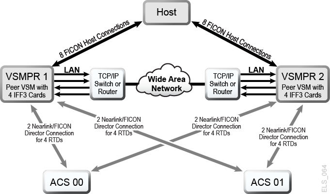
Description of ''Figure A-7 Clustered VSM5s with TCP/IP CLINKs''
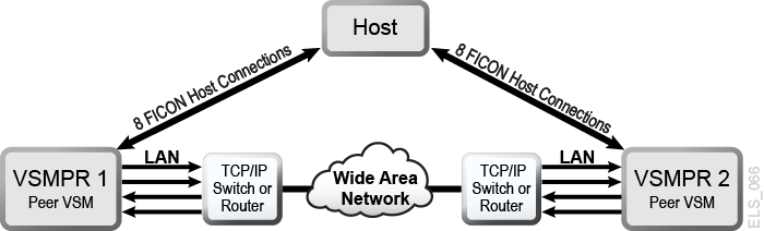
Figure A-7 shows an example of a VSM5 to VSM5 Cluster with TCP/IP CLINKs.
In Figure A-7, assume that for redundancy, you use targets on separate IFF cards on each VSM5 for Native IP as shown in Table A-1 and Appendix A.
Table A-1 CLINK IPIF Values for VSMPR1
| IFF Card | Target Number | Example IP | Corresponding CLINK IPIF |
|---|---|---|---|
|
IFF0 |
Target 0 |
128.0.1.1 |
0A:0 |
|
IFF1 |
Target 0 |
128.0.2.1 |
0I:0 |
|
IFF2 |
Target 0 |
128.0.3.1 |
1A:0 |
|
IFF3 |
Target 0 |
128.0.4.1 |
1I:0 |
Table A-2 CLINK IPIF Values for VSMPR2
| IFF Card | Target Number | Example IP | Corresponding CLINK IPIF |
|---|---|---|---|
|
IFF0 |
Target 0 |
128.0.1.2 |
0A:0 |
|
IFF1 |
Target 0 |
128.0.2.2 |
0I:0 |
|
IFF2 |
Target 0 |
128.0.3.2 |
1A:0 |
|
IFF3 |
Target 0 |
128.0.4.2 |
1I:0 |
The following example shows CONFIG JCL to define the configuration shown in Figure A-7 with the values shown in Table A-1 and Table A-2.
//CREATECF EXEC PGM=SLUADMIN,PARM='MIXED'
//STEPLIB  DD DSN=hlq.SEALINK,DISP=SHR
//SLSCNTL  DD DSN=FEDB.VSMLMULT.DBASEPRM,DISP=SHR
//SLSCNTL2 DD DSN=FEDB.VSMLMULT.DBASESEC,DISP=SHR
//SLSSTBY  DD DSN=FEDB.VSMLMULT.DBASETBY,DISP=SHR
//SLSPRINT DD   SYSOUT=*
//SLSIN    DD   *
 CONFIG CDSLEVEL(V61ABOVE)
GLOBAL MAXVTV=32000 MVCFREE=40 VTVATTR=SCRATCH RECALWER=YES
LOCKSTR=VTCS_LOCKS REPLICAT=ALWAYS VTVPAGE=LARGE INITMVC=YES
SYNCHREP=YES MAXRTDS=16 FASTMIGR=YES
RECLAIM THRESHLD=70 MAXMVC=40  START=35
VTSS NAME=VSMPR1 LOW=70 HIGH=80 MAXMIG=8 MINMIG=4 RETAIN=5
VTD LOW=8900 HIGH=89FF
RTD  NAME=VPR12A00 DEVNO=2A00 CHANIF=0C:0
RTD  NAME=VPR12A01 DEVNO=2A01 CHANIF=0C:1
RTD  NAME=VPR12A02 DEVNO=2A02 CHANIF=0C:2
RTD  NAME=VPR12A03 DEVNO=2A03 CHANIF=0C:3
RTD  NAME=VPR12A04 DEVNO=2A04 CHANIF=0G:0
RTD  NAME=VPR12A05 DEVNO=2A05 CHANIF=0G:1
RTD  NAME=VPR12A06 DEVNO=2A06 CHANIF=0G:2
RTD  NAME=VPR12A07 DEVNO=2A07 CHANIF=0G:3
VTSS NAME=VSMPR2 LOW=70 HIGH=80 MAXMIG=8 MINMIG=4 RETAIN=5
VTD LOW=9900 HIGH=99FF
RTD  NAME=VPR22B00 DEVNO=2B00 CHANIF=0C:0
RTD  NAME=VPR22B01 DEVNO=2B01 CHANIF=0C:1
RTD  NAME=VPR22B02 DEVNO=2B02 CHANIF=0C:2
RTD  NAME=VPR22B03 DEVNO=2B03 CHANIF=0C:3
RTD  NAME=VPR22B04 DEVNO=2B04 CHANIF=0G:0
RTD  NAME=VPR22B05 DEVNO=2B05 CHANIF=0G:1
RTD  NAME=VPR22B06 DEVNO=2B06 CHANIF=0G:2
RTD  NAME=VPR22B07 DEVNO=2B07 CHANIF=0G:3
CLUSTER NAME=CLUSTER1 VTSSs(VSMPR1,VSMPR2)
 CLINK VTSS=VSMPR1 IPIF=0A:0
 CLINK VTSS=VSMPR1 IPIF=0I:0
 CLINK VTSS=VSMPR1 IPIF=1A:0
 CLINK VTSS=VSMPR1 IPIF=1I:0
 CLINK VTSS=VSMPR2 IPIF=0A:0
 CLINK VTSS=VSMPR2 IPIF=0I:0
 CLINK VTSS=VSMPR2 IPIF=1A:0
 CLINK VTSS=VSMPR2 IPIF=1I:0
VSM5 to VSM 6 Cluster with TCP/IP CLINKs, Cross-Connected VLEs
Figure A-8 shows an example of a VSM5 to VSM 6 Cluster with TCP/IP CLINKs, where each VTSS is cross-connected to two VLEs.
Figure A-8 VSM5 to VSM6 Cluster with TCP/IP CLINKs, Cross-Connected VLEs
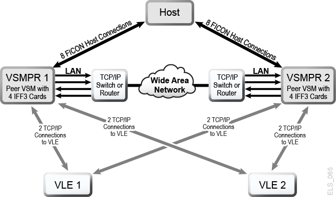
Description of ''Figure A-8 VSM5 to VSM6 Cluster with TCP/IP CLINKs, Cross-Connected VLEs''
In Figure A-8, assume that for redundancy, you will use targets on separate IFF cards for the VSM5 (VSMPR1) for Native IP and for VLE connections as shown in Table A-3 and Table A-4.
Table A-3 CLINK IPIF Values for VSMPR1
| IFF Card | Target Number | Example IP | Corresponding CLINK IPIF |
|---|---|---|---|
|
IFF0 |
Target 0 |
128.0.1.1 |
0A:0 |
|
IFF1 |
Target 0 |
128.0.2.1 |
0I:0 |
|
IFF2 |
Target 0 |
128.0.3.1 |
1A:0 |
|
IFF3 |
Target 0 |
128.0.4.1 |
1I:0 |
Table A-4 RTD IPIF Values for VSMPR1
| IFF Card | Target Number | Example IP | Corresponding CLINK IPIF |
|---|---|---|---|
|
IFF0 |
Target 1 |
128.0.1.2 |
0A:1 |
|
IFF1 |
Target 1 |
128.0.2.2 |
0I:1 |
|
IFF2 |
Target 1 |
128.0.3.2 |
1A:1 |
|
IFF3 |
Target 1 |
128.0.4.2 |
1I:1 |
The following example shows CONFIG JCL to define the configuration displayed in Figure A-8 with the values shown in Table A-3 and Table A-4.
//CREATECF EXEC PGM=SLUADMIN,PARM='MIXED'
//STEPLIB  DD DSN=hlq.SEALINK,DISP=SHR
//SLSCNTL  DD DSN=FEDB.VSMLMULT.DBASEPRM,DISP=SHR
//SLSCNTL2  DD DSN=FEDB.VSMLMULT.DBASESEC,DISP=SHR
//SLSSTBY   DD DSN=FEDB.VSMLMULT.DBASETBY,DISP=SHR
//SLSPRINT  DD   SYSOUT=*
//SLSIN     DD   *
CONFIG CDSLEVEL(V61ABOVE)
GLOBAL MAXVTV=32000 MVCFREE=40 VTVATTR=SCRATCH RECALWER=YES
LOCKSTR=VTCS_LOCKS REPLICAT=ALWAYS VTVPAGE=LARGE INITMVC=YES
SYNCHREP=YES MAXRTDS=16 FASTMIGR=YES
RECLAIM THRESHLD=70 MAXMVC=40  START=35
VTSS NAME=VSMPR1 LOW=70 HIGH=80 MAXMIG=8 MINMIG=4 RETAIN=5
VTD LOW=9900 HIGH=99FF
RTD  NAME=VL1RTD1 STORMNGR=VLE1 IPIF=0A:1
RTD  NAME=VL1RTD2 STORMNGR=VLE1 IPIF=0I:1
RTD  NAME=VL2RTD1 STORMNGR=VLE2 IPIF=1A:1
RTD  NAME=VL2RTD2 STORMNGR=VLE2 IPIF=1I:1
CLUSTER NAME=CLUSTER1 VTSSs(VSMPR1,VSMPR2)
 CLINK VTSS=VSMPR1 IPIF=0A:0
 CLINK VTSS=VSMPR1 IPIF=0I:0
 CLINK VTSS=VSMPR1 IPIF=1A:0
 CLINK VTSS=VSMPR1 IPIF=1I:0
 CLINK VTSS=VSMPR2 IPIF=0A:0
 CLINK VTSS=VSMPR2 IPIF=0I:0
 CLINK VTSS=VSMPR2 IPIF=1A:0
 CLINK VTSS=VSMPR2 IPIF=1I:0
In this example, note that while the CLINK IPIF and RTD IPIF parameter values for the VSM5 (VSMPR1) must match the values shown in Table A-3 and Table A-4, the CLINK IPIF and RTD IPIF values for the VSM 6 (VSMPR2) only have to meet VTCS restrictions on these values and must be unique for each VTSS; they do not correspond to an actual value on the VSM 6 TCP/IP ports.
VSM 6 to VSM 6 ”Tapeless” Cluster with TCP/IP CLINKs
Figure A-9 shows an example of a "Tapeless" VSM 6 to VSM 6 Cluster with TCP/IP CLINKs.
Figure A-9 VSM6 to VSM6 Tapeless Cluster with TCP/IP CLINKs
Description of ''Figure A-9 VSM6 to VSM6 Tapeless Cluster with TCP/IP CLINKs''
The following example shows CONFIG JCL to define the configuration shown in Figure A-9.
//CREATECF EXEC PGM=SLUADMIN,PARM='MIXED'
//STEPLIB  DD DSN=hlq.SEALINK,DISP=SHR
//SLSCNTL  DD DSN=FEDB.VSMLMULT.DBASEPRM,DISP=SHR
//SLSCNTL2 DD DSN=FEDB.VSMLMULT.DBASESEC,DISP=SHR
//SLSSTBY  DD DSN=FEDB.VSMLMULT.DBASETBY,DISP=SHR
//SLSPRINT DD   SYSOUT=*
//SLSIN    DD   *
CONFIG CDSLEVEL(V61ABOVE)
GLOBAL MAXVTV=32000 MVCFREE=40 VTVATTR=SCRATCH RECALWER=YES
LOCKSTR=VTCS_LOCKS REPLICAT=ALWAYS VTVPAGE=LARGE INITMVC=YES
SYNCHREP=YES MAXRTDS=16 FASTMIGR=YES
RECLAIM THRESHLD=70 MAXMVC=40  START=35
VTSS NAME=VSMPR1 LOW=70 HIGH=80 MAXMIG=8 MINMIG=4 RETAIN=5
VTD LOW=8900 HIGH=89FF
CLUSTER NAME=CLUSTER1 VTSSs(VSMPR1,VSMPR2)
 CLINK VTSS=VSMPR1 IPIF=0A:0
 CLINK VTSS=VSMPR1 IPIF=0A:1
 CLINK VTSS=VSMPR1 IPIF=0A:2
 CLINK VTSS=VSMPR1 IPIF=0A:3
 CLINK VTSS=VSMPR2 IPIF=0A:0
 CLINK VTSS=VSMPR2 IPIF=0A:1
 CLINK VTSS=VSMPR2 IPIF=0A:2
 CLINK VTSS=VSMPR2 IPIF=0A:3
In this example, note that the CLINK IPIF values for both VSM 6s only have to meet VTCS restrictions on these values and must be unique for each VTSS; they do not correspond to an actual value on the VSM 6 TCP/IP ports. Also note that because the cluster is tapeless, there are no CONFIG RTD statements for either VSM 6.
Should you Use Uni-Directional or Bi-Directional?
You can use VTSSLST and VTSSSEL statements to make a Bi-Directional Cluster Uni-Directional. Why would you want to do this? What if you wanted to switch the roles of the Primary and Secondary VTSSs? Start with the same setup as described in the procedure beginning on "Configuring and Managing a Bi-Directional Clustered System." After you complete Step 5, you make a change with the following VTSSLST and VTSSSEL statements.
VTSSLST NAME(SITEA) VTSS(VSMPR1)
VTSSSEL FUNCTION(SCRATCH) HOST(MVSA) VTSSLST(SITEA)
VTSSSEL FUNCTION(SPECIFIC) HOST(MVSA) VTSSLST(SITEA)
In this example:
-
The
VTSSLSTstatement defines VTSS list SITEA that contains only VSMPR1. -
The
VTSSSELstatements direct scratch and specific VTV mounts from MVSA to SITEA, which contains only VSMPR1, effectively making it the Primary.
So, this Cluster is actually Bi-Directional, but VTSSLST and VTSSSEL statements give us the flexibility to effectively make either VTSS the Primary and the other the Secondary by simply loading the corresponding MGMTclas, STORclas, VTSSLST, and VTSSSEL control statements with the MGMTDEF command.
What if you want to switch the Primary and Secondary? In this case, rewrite the VTSSLST and VTSSSEL statements to make VSMPR2 the Primary and VSMPR1 the Secondary.
VTSSLST NAME(SITEB) VTSS(VSMPR2)
VTSSSEL FUNCTION(SCRATCH) HOST(MVSB) VTSSLST(SITEB)
VTSSSEL FUNCTION(SPECIFIC) HOST(MVSB) VTSSLST(SITEB)
In this example:
-
The
VTSSLSTstatement defines list SITEB that contains only VSMPR2. -
The
VTSSSELstatements direct scratch and specific VTV mounts from MVSB to SITEB, which contains only VSMPR2, effectively making it the Primary.
Finally, what if the time came that things worked better with this Cluster as a true Bi-Directional Cluster? In this case, delete the VTSSLST and VTSSSEL statements and reload your definitions.