6 Using Clustered VTSS Configurations
Clustered VTSSs allow you to copy VTVs from one VTSS to another. Clustered VTSS is a powerful tool for applications such as but not limited to DR (Disaster Recovery) solutions. These sections discuss the basics of what VTSS Clusters are and how they work:
After the basics, there are additional variations and features of Clustered VTSS that you want to know about:
What is Clustered VTSS?
A VTSS cluster is a High Availability (HA) solution providing for maximum data availability. It consists of two or more VTSS systems connected using FICON or TCP/IP communication links (CLINKs). Additionally, every VTSS system within the cluster can access all data created within the cluster (VTSS resident or migrated). Data (VTVs) created on a cluster are replicated from one VTSS system to another VTSS within the same cluster under the control of VTCS policies.
Note:
To ensure that every VTSS system can access all data created within the cluster, clustered configurations can be either of the following:-
Each VTSS in the cluster has attached either RTDs or VLEs.
-
"Tapeless" - no VTSSs have VLEs or RTDs attached.
Clustered configurations, therefore, provide the highest data availability with a hot recovery if a VTSS within a cluster has an outage (replicated data remains available without requiring recalls from MVCs).
Before VTCS 7.0, a cluster could only consist of two VTSSs. With VTCS 7.0, many VTSSs can form a single cluster. A VTV, however, can only be resident in two VTSSs at any point in time.
A cluster can span geographic locations. A cluster, however, must be within a single TapePlex (controlled by a single CDS).
A VTV can be replicated (copied) from one VTSS to another either:
-
Asynchronously to the VTV creation. Scheduled to complete as soon as possible after the VTV dismount
-
Synchronously with the VTV creation. The VTV dismount will not complete until the replication is complete.
Note:
For synchronous replication, either through CLINKs or enhanced replication, the VTSS terminates the replication if the replication will cause the Missing Interrupt Handler (MIH) to be exceeded.For VSM 6 and VSM 7, the MIH timeout value can be configured from 20-45 minutes in 5 minute increments. For VSM4 and VSM 5, the MIH timeout value can be configured to be 20 or 45 minutes. The value set in the VTSS must match the value set at the mainframe.
The connections between VTSSs within a cluster can be either uni-directional, where data (VTVs) flows only one way or bi-directional, where data (VTVs) can flow in both directions. The CONFIG utility specifies whether a cluster is uni- or bi-directional, and a VTVs Management Class determines its replication policy, if any, and whether the replication is done synchronously or asynchronously.
So both vaulting MVCs (as described in "Using the ELS External Vaulting Feature") and VTV replication can facilitate a Disaster Recovery/Business Continuance solution. VTV replication, however, is superior as a High Availability solution because with replication:
-
Data can be backed up synchronously.
-
Recent data, which has been replicated to a "Recovery" VTSS, can be restored more quickly because you do not have to mount MVCs.
Clustered VTSS Requirements
Table 6-1 shows requirements for clustered VTSS.
Table 6-1 Clustered VTSS Requirements
| Component | Requirement |
|---|---|
|
Extended Clusters |
D02.07.00.00 or greater VTSS microcode for VSM4s or VSM5s with FICON connections only. For VSM 6 and VSM 7, all levels of microcode. |
|
2 VTSSs within a cluster (ESCON Interfaces) |
The Primary and Secondary VTSSs can be any combination of VSM4s where the Secondary can be of any capacity. VSM5s do not have ESCON interfaces, and cannot be in a cluster with other VTSSs that use ESCON |
|
2 VTSSs within a cluster (FICON Interfaces) |
The Primary and Secondary VTSSs can be any combination of VSM4 and VSM5 where the Secondary can be of any capacity. For example, all of the following are valid:
|
|
Primary and Secondary VTSS microcode |
The Primary VTSS microcode must be at a level that supports sending replicated VTVS. The Secondary VTSS microcode must be at a level that supports receiving replicated VTVS and supports the use of the Secondary as a production VTSS. After the microcode is installed, the Clustering feature must be enabled at both the Primary and Secondary VTSS using an options floppy disk.See your StorageTek hardware service representative for details. |
|
VTDs reserved for clustering |
In Clustered VTSS configurations, you must ensure that the first 16 VTDs in each VTSS (0-F) are reserved for clustering. These devices must be OFFLINE to MVS, and their paths must be online to each HSC server host. This also applies to any VTSSs involved in Cross TapePlex Replication. VTCS does not register the first 16 VTDs with SMC/HSC, which prevents mounting VTVs on these VTDs. |
|
RTDs |
In dual-ACS environments, the same device types must be represented in the RTDs attached to each ACS so that data migrated by any VTSS in a cluster can be recalled by any other VTSS in the cluster. The number of MVCs, the media type and location used for the migration is determined by the Each ACS needs to be considered and if a drive type in one ACS is connected to one of the VTSSs in a clustered VTSS environment, a drive of the same type and in the same ACS needs to be connected to every other VTSS in that clustered environment. |
|
Native IP (clustering with TCP/IP) |
Native IP requires CDSLEVEL F and above is required, with the following PTFs:
The following connections are supported for Native IP:
|
Synchronous replication, which applies to only VSM4 and above, has the requirements described in Table 6-2.
Table 6-2 Synchronous Replication Requirements
| Synchronous Replication Requirement | VTSS Microcode Level | CDS level |
|---|---|---|
|
Native IP or FICON ports for the CLINKs |
D02.03.00.00 or higher for VSM4s and VSM5s. For VSM 6 and VSM 7, all levels of microcode |
"F" or higher |
Enhanced replication, which applies to VSM6 and above, has the requirements described in Table 6-3.
How Clustered VTSS Configurations Work
You can use VSM to connect two VTSSs by Cluster Links (CLINKs) to form a Clustered VTSS configuration. You use the following statements to implement a Clustered Configuration:
-
Clusters can be either Uni-Directional or Bi-Directional depending on the
CLINKstatements. -
The Secondary VTSS (or the second Peer) can either be at the same physical location as the Primary (or first Peer) or at a remote location.
-
The
CONFIG CLUSTERstatement specifies the VTSSs that form the Cluster. -
The
CONFIG CLINKstatement defines the CLINKs that connect the VTSSs. The way you write theCLINKstatements determines whether the replication is uni-directional or bi-directional. For examples, see "Uni-Directional Clustered VTSS" and "Bi-Directional Clustered VTSS." -
The
MGMTclas REPLICATparameter identifies the Management Class that contains the VTVs that VSM replicates (copies) from one VTSS in the Cluster to the other.
The CONFIG GLOBAL REPLicat parameter now specifies when to replicate a VTV as follows:
- REPLicat
-
specifies when VSM replicates the VTV.
- ALWAYS
-
The replicate request is added to the VTCS replication queue every time the VTV is dismounted, regardless of whether the VTV was changed while it was mounted (the default).
- CHANGED
-
The replicate request is added to the VTCS replication queue if the VTV:
-
has been changed while it was mounted or
-
has been read only while mounted but less than the expected number of MVC copies of the VTV exist.
Regardless of the
CONFIG GLOBAL REPLicatsetting, replication also requires that:-
The VTV must be dismounted in a VTSS that supports replication and there cannot be an identical copy of the VTV in the other VTSS in the Cluster.
-
In addition to the
CONFIG GLOBAL REPLicatvalue, you must specifyREPLICAT(YES)on a VTV's Management Class for replication to occur.For more information, see ELS Command, Control Statement, and Utility Reference.
-
-
VTCS immediately migrates (with
KEEP) replicated VTVs. You can specify the source VTSS for migration of replicated VTVs on theMIGRATEparameter of theSTORclasstatement. Also note that you must specify replication on a Management Class that points to a Storage Class with aMIGRATEparameter value to migrate from the desired VTSS. Otherwise, migration from the desired VTSS may not occur.Because VTCS immediately migrates (with
KEEP) replicated VTVs regardless of theMGMTclas IMMDELAYsetting, StorageTek strongly recommends that you do not explicitly set aMGMTclas IMMDELAYpolicy for replicated VTVs. If you do, VTCS honors the explicit immediate migrate request, and immediately migrates the affected VTV from whichever VTSS is first capable of performing the migration (that is, the first VTSS that has a resident VTV copy and an available RTD to satisfy the migrate). Setting an explicitMGMTclas IMMDELAYpolicy, therefore, is redundant and may interfere with optimal VTV replication and migration.Also note that the immediate migrate (
KEEP) following replication is not the same as automigration. That is, during the implicit immediate migrate, no VTVs are deleted from either VTSS to manage the DBU. Instead, the VTVs are simply "pre-staged" using migration to an MVC from the receiving VTSS, leaving both VTSS buffer contents unchanged. For space management in a VTSS cluster, VTCS automigrates VTVs according to the space management/migration cycle of either VTSS. If the capacity of the receiving VTSS is greater than or equal to that of the sending VTSS, automigration on the sending VTSS deletes a replicate VTV from both the VTSSs. If the capacity of the receiving VTSS is less than that of the sending VTSS, automigration may start on the receiving VTSS. In this case, automigration deletes a replicate VTV from only the receiving VTSS, leaving the copy on the sending VTSS still resident. -
Note that the replication requirements of data is determined following a dismount, not a recall. Recalling a VTV will not cause a replicate – so demand recall,
MVCdrainand reclaim will not cause a replicate. However, if the VTV is recalled and mounted on a VTD, at dismount time it will be replicated to the Secondary or Peer VTSS. -
A Cluster can support different workloads in each of four operating modes. For example, only Full-Function Clusters can support active replication, but in Degraded Primary Mode, you can vary the Secondary's VTDs online to MVS to take over the workload. You can use
Queryto display Cluster, Cluster link, VTV replication, and VTSS status. You can useVARY VTSSto change VTSS states andVARY CLinkto change CLINK states.
How VTSS Reconciliation Works
-
Whenever a clustered VTSS-pair resumes the full function state, VTCS reconciles the contents of the two VTSSs. This occurs either during VTCS initialization or when a VTSS goes online and its partner VTSS is also online.
-
Reconciliation consists of either deleting or migrating and deleting VTVs (or replicating a VTV if this had not previously completed successfully). That is, recall is not involved in reconciling VTSS contents.
For example, in a uni-directional cluster with a VTV resident in the receiver but not the sender VTSS, VTCS deletes the VTV from the receiver (after ensuring that all required MVC copies have been made). This avoids a recall to the sender.
Similarly, in a uni-directional cluster with a VTV resident in the sender but not the receiver, VTSS, VTCS replicates the VTV to the receiver instead of recalling it from an MVC.
-
The reconcile process assumes that if a replicated VTV is resident on the sender VTSS, then it is a valid copy. If the copy on the receiver is different, VTCS deletes it.
-
To maintain consistent reconcile actions in a bi-directional cluster, the VTSS in which the VTV is or was last resident (as indicated by the CDS VTV record), is considered to be the sender VTSS. Reconcile processing is as described above for uni-directional clusters.
Uni-Directional and Bi-Directional Clusters
Clusters of two VTSSs can be either of the following:
-
Uni-directional, where one VTSS is the Primary and the other is the Secondary. For more information, see "Uni-Directional Clustered VTSS."
-
Bi-directional, where both VTSSs are peers and replication is from Peer to Peer in either direction. For more information, see "Bi-Directional Clustered VTSS."
Uni-Directional Clusters
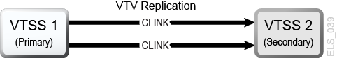
As shown in Figure 6-1, in a Uni-Directional Cluster, replication is only from the Primary to the Secondary.
Figure 6-1 Uni-Directional Clustered VTSS
Description of ''Figure 6-1 Uni-Directional Clustered VTSS''
How Uni-Directional VTSS Clusters Work
-
The Secondary can receive both replicated VTVs from the Primary and non-replicate production workload by any of the standard routing methods (for example,
TAPEREQs). You need to vary the VTDs in the Secondary online to MVS so that the Secondary can accept production work. You cannot vary online to MVS the VTD addresses used by the CLINK terminations as described in "How Clustered VTSS Configurations Work." -
A VTV with replication enabled is allocated to an online Primary VTSS unless none are available; in that case, the VTV is allocated to an online Secondary VTSS. If no online Secondary VTSSs are available, the VTV is allocated to a non-cluster VTSS. A VTV without replication can be allocated to any online VTSS including the Secondary of a Full-Function Cluster.
-
At dismount time, a VTV with replication enabled that resides on a Full-Function Cluster is queued for replication to the Secondary VTSS. If a VTV with replication enabled is dismounted from a VTD in a VTSS that is not part of a Full-Function Cluster, the VTV is queued for immediate migration.
When the Secondary VTSS receives a replicated VTV from the Primary VTSS, the VTV is then immediately migrated (with the
KEEPoption) regardless of Immediate Migrate Management Class settings for this VTV. -
Both the Primary and the Secondary VTSS can manage all space reclamations.
-
If you are using ESCON or FICON interfaces, on the Primary VTSS, the CLINK CIPs/FIPs are configured in Nearlink Mode, while on the Secondary VTSS, the CIPs/FIPs are configured in Host Mode.
Therefore, you configure
CLINKs for only the Primary VTSS, as shown in the following example, where VTSS1 is the Primary VTSS.. . CLUSTER NAME=CLUSTER1 VTSSs(VTSS1,VTSS2) CLINK VTSS=VTSS1 CHANIF=0G CLINK VTSS=VTSS1 CHANIF=0O CLINK VTSS=VTSS1 CHANIF=1G CLINK VTSS=VTSS1 CHANIF=1O . .
Bi-Directional Clusters
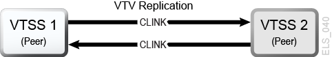
As shown in Figure 6-2, Bi-Directional Clustering, requires pairs of Uni-Directional CLINKs so that the data flows in opposite directions on the CLINKs.
Figure 6-2 Bi-Directional Clustered VTSS
Description of ''Figure 6-2 Bi-Directional Clustered VTSS''
How Bi-Directional VTSS Clusters Work
In a Bi-Directional Cluster, in normal operation, both VTSSs are online to VTCS as follows:
-
In a Bi-Directional Cluster, each of the Peer VTSSs can receive production work through the standard routing methods (for example, TAPEREQs). You need to vary the VTDs in both VTSSs online to MVS so that each can accept production work. However, note that you cannot vary online to MVS the VTD addresses used by the CLINK connections as described in "How Clustered VTSS Configurations Work."
-
In a Bi-Directional Cluster, a VTV with replication enabled is allocated to either of the Peer VTSSs. If one of the two Peer VTSSs is either offline or quiesced, production workload can run on the remaining online VTSS. VTVs requiring replication, however, are allocated to the remaining VTSS only if no other Full-Function clusters are available and suitable. In this case, replicate VTVs are migrated immediately with keep and queued for replication when the other VTSS comes online.
-
In a Bi-Directional Cluster, at dismount time, a VTV with replication enabled that resides on a Full-Function Cluster is queued for replication to the other Peer VTSS. If a VTV with replication enabled is dismounted from a VTD in a VTSS that is not part of a Full-Function Cluster, the VTV is queued for immediate migration. Note that the replication requirements of data is determined following a dismount, not a recall. Recalling a VTV will not cause a replicate – so demand recall, MVCdrain and reclaim will not cause a replicate. However, if the VTV is recalled and mounted on a VTD, at dismount time it will be replicated to the Secondary VTSS unless you specify REPLICAT(CHANGED) (the recommended option), which will cause the VTV to be replicated again only if the data is changed.
-
Both Peer VTSSs can manage all space reclamations.
-
If you are using ESCON or FICON interfaces:
-
On the each peer VTSS, the "sending"
CLINK CIPs/FIPsare configured in Nearlink Mode, while the receivingCLINK CIPs/FIPsare configured in Host Mode.Therefore, you configure "sending"
CLINKs on each Peer VTSS, as shown in the following example, where VSMPR1 and VSMPR2 are Peer VTSSs.. . CLUSTER NAME=CLUSTER1 VTSSs(VSMPR1,VSMPR2) CLINK VTSS=VSMPR1 CHANIF=0O:0 CLINK VTSS=VSMPR1 CHANIF=0O:1 CLINK VTSS=VSMPR2 CHANIF=1O:0 CLINK VTSS=VSMPR2 CHANIF=1O:1 . .
-
-
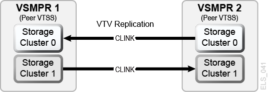
Each CLINK must be attached to the same Storage Cluster on each VTSS (Storage Cluster 0 to Storage Cluster 0 or Storage Cluster 1 to Storage Cluster 1). Failure to configure in this manner can produce Replicate, Channel, and Communication errors.
As shown in the example in Figure 6-3, the sending (Nearlink mode) CLINK port on VSMPR1 is on Storage Cluster 1, and it connects to a receiving (Host Mode) CLINK port,
also on Storage Cluster 1on VSMPR2. Similarly, a sending CLINK port on Storage Cluster 0 of VSMPR2 connects to a receiving CLINK port on Storage Cluster 0 of VSMPR1.Figure 6-3 ESCON/FICON CLINKs for Bi-Directional Clustered VTSSs
Description of ''Figure 6-3 ESCON/FICON CLINKs for Bi-Directional Clustered VTSSs''
Extended Clustering
Extended Clustering (EC) allows three or more VTSSs to be connected by Clinks within a single Tapeplex (1 CDS) configuration. Clustering is a high-availability solution designed such that workload can continue without disruption on a VTSS outage. Clustering requires that all VTSS subsystems that are part of a cluster have access to all MVCs generated by any single VTSS subsystem in that cluster. If a VTSS within a cluster connects to a remote Tapeplex (CTR) then all VTSS systems in the cluster must connect to the same Tapeplex to retain the HA capability.
With Extended Clustering, you can configure one VSM with Clinks connected to multiple VTSSs and the number of Clink connections are only limited by the number of physical connections available. D02.07.00.00 or greater micro code is required. All of the clustering and replication rules available are applied to EC. All Extended Cluster configurations are built based upon the two basic Uni-directional configurations shown in Figure 6-4.
Figure 6-4 Basic Extended Cluster Configurations
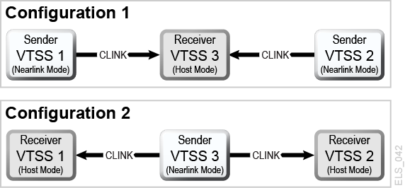
Description of ''Figure 6-4 Basic Extended Cluster Configurations''
Synchronous or Asynchronous Replication
You have a choice: you can either replicate synchronously or asynchronously, depending on your site's policies.
Implementing Synchronous Replication
Caution:
With synchronous replication the time required to replicate a virtual volume will delay the completion of any job creating data that has a synchronous replication policy.-
Ensure that your system has the Synchronous Replication requirements described in Table 6-2.
-
With all HSC/VTCS systems down, use
CONFIG GLOBALto enable Synchronous Replication:CONFIG GLOBAL SYNCHREP=YES
-
Ensure that the
CONFIG GLOBAL REPLICATparameter is set as desired:- ALWAYS
-
The replicate request is added to the VTCS replication queue every time the VTV is dismounted, regardless of whether the VTV was changed while it was mounted (the default).
- CHANGED
-
The replicate request is added to the VTCS replication queue if the VTV:
-
has been changed while it was mounted or
-
has been read only while mounted but less than the expected number of MVC copies of the VTV exist.
-
-
Specify Synchronous Replication on the desired
MGMTClasstatements:MGMT (name) ..... REP(YES_SYNC)
Implementing Asynchronous Replication with Job Monitoring
You may elect to use Asynchronous Replication but may also want to know that the replication completed successfully. In this procedure, you use the DRMONitr utility to monitor to pause the associated MVS job until the replication completes successfully.
-
Ensure that your system has the Synchronous Replication requirements described in Table 6-2.
-
With all HSC/VTCS systems down, use
CONFIG GLOBALto enable Asynchronous Replication:CONFIG GLOBAL SYNCHREP=NO
-
Ensure that the
CONFIG GLOBAL REPLICATparameter is set as desired:- ALWAYS
-
The replicate request is added to the VTCS replication queue every time the VTV is dismounted, regardless of whether the VTV was changed while it was mounted (the default).
- CHANGED
-
The replicate request is added to the VTCS replication queue if the VTV:
-
has been changed while it was mounted or
-
has been read only while mounted but less than the expected number of MVC copies of the VTV exist.
-
-
Specify Asynchronous Replication on the desired
MGMTClasstatements:MGMT (mgmtname) ..... REP(YES) -
Create JCL to monitor the asynchronous replication.
For this, use the
DRMONitrutility to monitor the replication.DRMONitrcauses the associated MVS job to pause until the replication completes successfully. For example://MONITOR EXEC PGM=SLUADMIN,PARM='MIXED' //STEPLIB DD DSN=hlq.SEALINK,DISP=SHR //* If HSC IS NOT OR MAY NOT BE ACTIVE, INCLUDE THE //* FOLLOWING: //SLSCNTL DD DSN=primary.cds.name,DISP=SHR //SLSCNTL2 DD DSN=secondary.cds.name,DISP=SHR //SLSSTBY DD DSN=standby.cds.name,DISP=SHR //SLSPARMP DD DSN=hlq.PARMLIB(BKPCNTL),DISP=SHR //SLSPARMS DD DSN=hlq.PARMLIB(BKPCNTL2),DISP=SHR //SLSPARMB DD DSN=hlq.PARMLIB(BKPSTBY),DISP=SHR //SYSIN DD UNIT=SYSDA,SPACE=(TRK,1) //* THE FOLLOWING IS USED BY THE SNAPSHOT UTILITY: //SYSPRINT DD SYSOUT=* //SLSPRINT DD SYSOUT=* //SLSIN DD * DRMON MGMT(mgmtname) REPL MAXAGE(24) TIMEOUT(120)
In this example, the DRMON utility monitors the replicates for the specified Management Class. Additionally, monitor only VTVs that have been updated in the last 24 hours, and time out DRMON after 120 minutes.
Clustering with TCP/IP Connections
The VTSS native IP connection feature lets you use TCP/IP protocol to "cluster" (connect) two or more VTSSs for VTV replication. With Native IP clustering, each VTSS has Ethernet ports for connection to the TCP/IP network. Previously, you were limited to ESCON or FICON connections for replication. Using TCP/IP for CLINKs can provide improved replication performance over ESCON or FICON protocols and, if so desired, allows the existing ESCON or FICON ports to be used exclusively for RTD and host connections, where the following are supported:
-
VSM5 to VSM5
-
VSM5 to VSM 6
-
VSM 6 to VSM 6
This section describes only the VTCS implementation for Native IP. Your StorageTek hardware support personnel or other QSPs are responsible for the VTSS side configuration.
The TCP/IP Environment
TCP/IP attached CLINKs perform the same function as FICON or ESCON channel attached CLINKs, but TCP/IP CLINK connects using an Ethernet port on the VTSS instead of from an ESCON or FICON port. The example in Figure 6-5 shows Peer VSM5s, each with 4 IFF3 cards with Ethernet ports. The Ethernet cables from the Ethernet ports on the IFF3 cards attach to Local Area Networks (LANs, one for each VTSS) and the LANs are connected through a Wide Area Network (WAN).
Figure 6-5 TCP/IP Environment with Two VSM5s
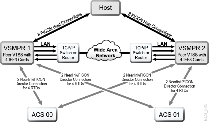
Description of ''Figure 6-5 TCP/IP Environment with Two VSM5s''
Configuring VTCS for TCP/IP CLINKs
The following shows the parameters for the CONFIG CLINK statement.
CONFIG CLINK Statement
The CONFIG CLINK statement provides two types of VTSS-to-VTSS connections through the following parameters:
- CLINK CHANIF=nn or nn:n
-
defines a FICON or ESCON port for use as a CLINK.
- CLINK IPIF=ci:p
-
defines an Ethernet port for use as a CLINK. Valid values for
CONFIG RTD IPIFare c=0 or 1, i=A or I, p=o through 3 for VSM5s and VSM 6s. For VSM5s, this value must match the values specified on the VSM5 IFF Configuration Status Screen. For VSM 6s, this must be unique for each VTSS; and does not correspond to an actual value on the VSM 6 TCP/IP ports.Note:
TheCLINKstatement must contain either theCHANIFor theIPIFparameter, but not both.