7 Using the Concurrent Disaster Recovery Test Software
Customers that use or maintain a Disaster Recovery (DR) site as part of a business continuance plan may want to periodically validate their ability to continue normal production processing before an actual disaster occurs; other customers do not have a choice and must periodically demonstrate the readiness of their business continuance model to satisfy insurance requirements and/or their auditors.
Using the Concurrent Disaster Recovery Test (CDRT) facility, now an integrated feature of StorageTek ELS software, those businesses currently using StorageTek Streamline and/or Nearline (real hardware) tape libraries, VSM (virtual hardware), and associated software (HSC, VTCS) can validate their real and virtual tape business continuance capability without the need to purchase additional hardware and software.
CDRT supports a parallel test of production hosts and applications with simultaneous access to production data by both the production and the DR test systems.
Key CDRT concepts include the following:
-
Using CDRT, a DR test can execute with real hardware, virtual hardware, or both.
-
CDRT, HSC, and VTCS programmatically enforces certain functional restrictions during the CDS preparation and actual DR test in an attempt to ensure system integrity.
-
CDRT logically separates a portion of existing production real and virtual hardware and tape volume pools for the period of the DR test. This allows testing of your DR configuration while concurrently running production work, ensures the integrity of the production data, and minimizes conflicts for tape volumes and hardware resources.
-
CDRT creates a test copy of the production CDS. The production ELS subsystem and the DR test ELS subsystems therefore do not communicate with each other. Changes that occur in the DR test CDS are not reflected in the production CDS copy and vice versa. The DR test hosts exercise the logically separated hardware only. The production hosts continue to use all hardware with one exception: the DR hosts have exclusive use of any logically separated VTSSs during the DR test. Other resources, like RTDs, Multiple Virtual Cartridges (MVCs) and real scratch tapes, must be controlled by defining separate pools to each set of hosts.
-
A DR test can be conducted using local resources only or with a combination of local and remote resources; configurations consisting of a remote site with real and virtual hardware only, or real and virtual hardware with a mainframe processor, are also supported.
-
The DR test hardware may include any combination of ACSs, VTSSs, and VLEs.
-
After a DR test, the test copy of the CDS and all data created from the DR test are typically discarded and the logically separated hardware is redeployed back to the normal production environment.
Note:
-
To satisfy the requirements of recovering from a true disaster, it is critical that jobs in a DR test jobstream do not update any volumes created in production, either through
DISP=MODor by overwriting these volumes. The use of such practices means that if a true disaster occurred, the state of these volumes would be unpredictable. -
For the DR test run, it is strongly recommended that production volumes that could be modified during the DR test are copied to new volumes at the beginning of the test, and that the copied volumes are updated by the DR test, not the original volumes. Also, JCL should be modified if possible so that the status of all tape volumes at the time of a disaster is known.
-
Metadata Considerations
Fundamental to the execution of a successful DR test using CDRT is a consistent copy of the state of all tape volumes managed by ELS software and the real and virtual hardware. The consistency in the state of tape volumes between the production hosts and the DR hosts at the start of the DR test is what allows the parallel processing of customer applications. Since the CDS reflects the state of all tape volumes and resources in the real and virtual hardware, CDRT partially meets this consistency requirement for you when it makes its test copy of the CDS.
In a tape volume environment, however, quite often some of this tape volume state data (metadata) is retained and managed outside of the ELS subsystem and the real and virtual hardware. Typically, tape volume metadata (that is, VOLSER, DSN, Expiration date, scratch status, real or virtual designation, and so forth) is stored in one or more Tape Management Catalogs (TMCs), one or more z/OS catalogs and the CDS.
You must coordinate the creation of copies of metadata retained and managed outside of ELS (and the real and virtual hardware) with the creation of the test copy of the CDS by CDRT.
Where Does CDRT Get Its VTV Data?
CDRT gets its VTV data from one or more of the following DR site resources:
-
MVCs
-
VLEs
-
VTSSs
Because the production CDS is the source of information about VTVs available to the DR test, it is important to ensure that the scratch synchronization cycle allows that volumes used in the DR test are not put into scratch status before the start of the test. StorageTek also recommends that you vary your test VTSS offline before doing your DRTEST CREATE.
Note that running scratch during the test does not affect the contents of the DR test VTSS, nor of the MVCs, if these are set to READONLY using the ACTMVCGN utility.
The DR site CDS copy provides the location of the VTVs at the time of the copy, and the location is usually on MVCs or VLEs. Sometimes, however, you may choose to use VTV copies in a VTSS that exists at the test site. In general, you can do this in the following situations:
-
You define your DR VTSS with the
SHAREkeyword, which prevents updates to the contents of any production VTV. -
You have two clustered VTSSs with one at the production site and one at the DR site and your DR test does not modify the contents of any production VTV.
-
You have two clustered VTSSs with one at the production site and one at the DR site and you are willing to spend time after your DR test to identify and manually migrate any VTV that was updated by the DR test.
Note:
You can use theDRMONitrutility to ensure critical DR data reaches its designated recovery location before running a DR test.
What Happens to Data When the Test is Over?
Data that is created by the DR test is reflected only in the DR test CDS (which is discarded after the test) and on the DR test MVCs, which are in a segregated range of volumes from the production MVCs. In addition, VTVs created by the DR test remain on the DR test VTSS after the test, unless you do one the following:
-
Use the
SLUADMIN SCRATCHutility in the DR test environment to scratch (withMGMTCLAS DELSCR(YES)) all VTVs in the DR test subpool range. This option requires the use of thePOOLPARM/VOLPARMfeature. -
Ensure that all production VTVs that have been modified by the DR test are migrated to DR test MVCs using the
MIGRATEcommand withDELETE(YES)from the DR test system. If you fail to do this, the production system picks up data that has been modified by the DR test. -
Have your StorageTek CSE or other QSP "clean" the DR test VTSS following the test to remove all data from the VTSS.
Note:
If you use either Option 2 or Option 3, the contents of the VTSS will not match the production system, because VTVs are missing from the DR test CDS when it is returned to production. Although this condition is handled by the software, your production performance may be degraded.
Managing CDRT Resources
The following sections tell how to manage CDRT resources.
Volume Resources
The first step in managing CDRT resources is to define the volumes in your system using the POOLPARM/VOLPARM utility. This feature simplifies overall management of your tape pools and volumes, and provides a method of segregating volumes that are written to in a CDRT configuration.Using POOLPARM/VOLPARM is required when DR test VTSSs are shared, and is strongly recommended in for other scenarios.
Note:
TheSLUADMIN SET VOLPARM utility must be run using the production CDS and must define both production and DR test pools. The SET VOLPARM utility is not valid for a DR test CDS.Scratch Subpools
Scratch subpools are applicable to all DR test scenarios. The following syntax shows using the POOLPARM/VOLPARM definitions to define production and DR test scratch subpools. By using the same names for subpools in production and DR test (with different volume ranges), you do not have to change your production policies when running the DR test as shown in the following example.
*   SCRATCH POOLS
POOLPARM NAME(SCRP1) TYPE(SCRATCH)
VOLPARM VOLSER(T11000-T11999) MEDIA(T10000T1) RECTECH(T1AE)
POOLPARM NAME(SCRP1) TYPE(SCRATCH) DRTEST
VOLPARM VOLSER(T12000-T12999) MEDIA(T10000T1) RECTECH(T1AE)
POOLPARM NAME(SCRVTV1) TYPE(SCRATCH)
VOLPARM VOLSER(V1000-V1999) MEDIA(VIRTUAL)
POOLPARM NAME(SCRVTV1) TYPE(SCRATCH) DRTEST
VOLPARM VOLSER(V2000-V2999) MEDIA(VIRTUAL)
When you define scratch subpools using the POOLPARM/VOLPARM utility, you can use the HSC SLUADMIN SCRATCH utility to scratch DR test output volumes within the DR test environment. In combination with a Management Class that specifies DELSCR(YES), running the scratch utility removes VTVs created by the DR test from the VTSS.
MVC Resources
MVC resources are used for all DR test scenarios except for real tape only and tapeless VSM. The following example shows using POOLPARM/VOLPARM definitions to define production and DR test MVC pools.
*   MVC POOLS
POOLPARM NAME(MVCP1) TYPE(MVC) MVCFREE(40) MAXMVC(4) THRESH(60) +
START(70)
VOLPARM VOLSER(T14000-T14999) MEDIA(T10000T1) RECTECH(T1AE)
POOLPARM NAME(MVCP1) TYPE(MVC) MVCFREE(40) MAXMVC(4) THRESH(60) +
START(70) DRTEST
VOLPARM VOLSER(T13000-T13999) MEDIA(T10000T1) RECTECH(T1AE)
Preserve the contents of production MVCs for use in a DR test scenario using the following:
-
Use the
ACTMVCGNutility to set MVCs that will be used as input to the DR test toREADONLYas shown in the following example.//ACTMVCG1 EXEC PGM=SLUADMIN,PARM='MIXED' //STEPLIB DD DSN=hlq.SEALINK,DISP=SHR //SLSPRINT DD SYSOUT=* //* NOTE: MVCMAINT READONLY(ON) STATEMENTS //SLUSMVON DD DSN=hlq.SLUSMVON,DISP=(NEW,CATLG,DELETE), // SPACE=(CYL,1) //* NOTE: MVCMAINT READONLY(OFF) STATEMENTS //SLUSMVOF DD DSN=hlq.SLUSMVOF,DISP=(NEW,CATLG,DELETE), SPACE=(CYL,1) //* NOTE: THE FOLLOWING STEP SELECTS ALL "ACTIVE" MVCS //* IN ACS 01. //SLSIN DD * ACTMVCGN ACS(01) /* //ACTMVCG2 EXEC PGM=SLUADMIN,PARM='MIXED' //STEPLIB DD DSN=hlq.SEALINK,DISP=SHR //SLSPRINT DD SYSOUT=* //* NOTE: EXEC MVCMAINT TO SET READONLY(ON)
-
Ensure that reclaim is not run on all production hosts using
VTCS CONFIG:CONFIG HOST NAME(host) NORECLAM
VTSS Resources
There are two types of VTSS resources: non-shared and shared.
Non-shared VTSS Resources
In an environment where VTVs are migrated to MVCs or to VLE, VTSS resources are segregated during a DR test. The DR test system has access only to VTSSs that are defined through the DRTEST PRIMEPRD/CREATE utilities and these VTSSs must remain offline to production. The DRTEST START command is rejected if a DR VTSS is online in the production environment.
In some cases, there may be two VTSSs with the same name in both the production and test sites. In this case, the SPARE parameter of the DRTEST PRIMEPRD/CREATE utility specifies that the DR test VTSS has the same name as a production VTSS but is not physically the same device, allowing the production device to remain online during the test. Do not use the SPARE parameter for any other scenarios!
Clustered VTSS in CDRT
"Scenario 4: Clustered VTSSs with Production and DR Test Sites" uses clustered VTSSs to deliver data to the VTSS at the DR site. In this scenario, the cluster does not function during the DR test because the DR test VTSS is offline to production.
If production VTVs are modified in any way during the DR test, you must ensure that the modified VTVs are removed from the VTSS before varying the test VTSS back online to production. Otherwise, the modified VTVs can be picked up by the production site. To prevent this situation, StorageTek strongly recommends that the DR test is designed so that production VTVs are not altered by the test.
In a Clustered VTSS scenario there may be no VTDs in the test VTSS accessible to the production host. To allow ECAM communication from production to the DR test VTSS, specify the following in VTCS CONFIG:
VTD LOW=xxxx HIGH=xxxx NOVERIFY
Preparing a VTSS Cluster for a DR Test:
-
Vary the DR test VTSS to quiesced state. For example:
VARY VTSS1 QUIESCED
The objective here is to (gracefully) shut down replication to VTSS1 so you can use it exclusively for the DR test.
-
Monitor replication until it completes with
Display REPLicat. Here, replication is still active:VTSS HOST QDEPTHVTSS0 PRODUCTION 1
You know replication is complete when you see this:
VTSS   HOST  QDEPTH
VTSS0  PRODUCTION  0
-
Cross check that replication is complete by checking the CLINK status with
Display CLINK. Here, the CLINK is still active:VTSS CLINK STATUS USAGE HOST VTSS0 7 ONLINE REPLICATING PRODUCTION VTSS0 8 ONLINE REPLICATING PRODUCTION You know the CLINK is no longer active when you see this: VTSS CLINK STATUS USAGE HOST VTSS0 7 ONLINE FREE VTSS0 7 ONLINE FREE
-
Vary the DR Test VTSS offline:
VARY VTSS1 OFFLINE
Managing VTSS Contents Before and After the DR Test
Before you start a DR test, you must:
-
Plan your test so that test output does not accidentally get into production.
-
Prepare your test so that your DR test CDS matches the DR VTSS contents.
Additionally, StorageTek strongly recommends that all test site VTSSs are cleaned as soon as possible after the test. This practice ensures that the test site VTSSs are empty at the start of the next test and that no DR test data remains on VTSSs that are returned to production.
You can clean test VTSSs by doing either of the following:
-
Do not allow the DR test to perform any updates (overwrite or append) to the production VTVs, and use
POOLPARM/VOLPARMto define DR test scratch subpools. With this method, you can run the scratch utility to scratch all VTVs in the DR test range and they are automatically deleted from the VTSS (if the Management Class specifiesDELSCR(YES)). -
If your DR test can update production VTVs, then you must ensure that any VTSS used for DR test output is emptied before returning the VTSS to production. This can be done by migrating to zero in the DR test environment, or by having the StorageTek CSE or other QSP "clean" the VTSS.
When you run the DRTEST CREATE utility to create the DR test CDS, metadata about the VTSS contents is propagated to the test environment. VTVs on the DR test VTSS are available to the DR test environment.
If the DR test VTSS is defined as a spare, then the contents of the physical DR VTSS will not match the CDS metadata, which references the production instance of the spare VTSS. To remove the discrepancy, before creating the DR test CDS, migrate the production instance of the spare VTSS to 0 in the production environment. You can run VTCS VTVRPT OPTION(UNAVAIL) to ensure that all VTVs are migrated and are available to other VTSSs. If this step is not performed, DR test attempts to access VTVs on the spare VTSS will issue SLS6680E messages for VTV mounts.
Shared VTSS Resources
If the tape environment does not include either real tape or VLE MVCs, You can run CDRT in a shared VTSS environment. The DRTEST PRIMEPRD/CREATE SHARE parameter specifies that a VTSS is shared between production and DR test during the test. This environment enforces the following restrictions:
-
DRTEST CREATEcannot also define any DRACS or STORMNGR resources. That is, no data can be migrated from the shared VTSS to external media. -
The production system must define volume resources using the
POOLPARM/VOLPARMfacility. -
Mounts of a non-DRTEST subpool VTV in the DR test environment forces the VTV to be readonly. That is, the DR test is not allowed to overwrite or append to any production VTV.
ACS Resources
ACS resources are used for DR test scenarios with real tape only or with virtual tape without VLE in a non-tapeless VSM environment. ACS resources for CDRT are specified in the DRTEST PRIMEPRD/CREATE DRACS parameter.
DR Test ACS Restrictions
You must issue the HSC CAPPREF command to set the CAPs to manual before running the DRTEST CREATE utility. The software insures that they remain in that state as long as the test is in effect. After you enter the DRTEST START command, restrictions are enforced on the DR test ACS in both the production and in the DR test environment to ensure consistency between the hardware and the respective CDSs to permit both sites to access the data. The DRTEST START command is rejected if a CAP in a DR test ACS is in automatic mode in the production environment.
The following restrictions are automatically enforced by the software.
DR Production Host Requirements
DR production host requirements during an active DR test for the DR ACS include:
-
CAPs must remain in manual mode.
-
FLOAT(OFF)andEJCTAUTO(OFF)are automatically enforced, regardless of the settings in the MNTD command. -
You cannot run eject, move, audit, and scratch utilities for the DR test ACS.
DR Test Host Requirements
DR test host requirements during a DR test include:
-
Non-DR test ACSs cannot be varied online.
-
CAPs must remain in manual mode.
-
FLOAT(OFF)andEJCTAUTO(OFF)automatically enforced and the other values are not valid on the MNTD command. -
You cannot run eject, move, audit, and scratch utilities for the DR test ACS.
-
Scratch updates are allowed only for volumes defined using
POOLPARM/VOLPARMas DR test scratch subpool volumes.
VLE Resources
You define VLE resources using the STORMNGR parameter of the DRTEST PRIMEPRD and CREATE commands. Typically, the DR test resources are either ACSs or VLEs, although there is no restriction on using both.
Like physical MVCs, VLE VMVCs are defined using the POOLPARM/VOLPARM facility, with a range of VMVCs reserved for the DR test. The DR test also has read access to the production VMVCs as shown in the following example.
//ACTMVCG1 EXEC PGM=SLUADMIN,PARM='MIXED'
//STEPLIB  DD DSN=hlq.SEALINK,DISP=SHR
//SLSPRINT DD SYSOUT=*
//* NOTE: MVCMAINT READONLY(ON) STATEMENTS
//SLUSMVON DD DSN=hlq.SLUSMVON,DISP=(NEW,CATLG,DELETE),
// SPACE=(CYL,1)
//* NOTE: MVCMAINT READONLY(OFF) STATEMENTS
//SLUSMVOF DD DSN=hlq.SLUSMVOF,DISP=(NEW,CATLG,DELETE),
SPACE=(CYL,1)
//* NOTE: THE FOLLOWING STEP SELECTS ALL "ACTIVE" MVCS
//* IN VLE1 AND MVCPOOL MVCP1.
//SLSIN DD *
ACTMVCGN STORMNGR=VLE1,MVCP=MVCP1
/*
//ACTMVCG2 EXEC PGM=SLUADMIN,PARM='MIXED'
//STEPLIB  DD DSN=hlq.SEALINK,DISP=SHR
//SLSPRINT DD SYSOUT=*
//* NOTE: EXEC MVCMAINT TO SET READONLY(ON)
//SLSIN DD DSN=hlq.SLUSMVON,DISP=SHR
VTCS Policies
To minimize the differences between your production and DR test environments, CDRT allows you to define policies for managing VTVs that have the same name in both production and DR test environments, but different policy definitions.
Note that the production and test sites can share a VTSS using the DRTEST DRVTSS SHARE parameter. Also note that the specifying a dummy DR ACS is no longer required for a shared VTSS or a DR test using VLE. Specifying a shared VTSS has the following restrictions:
-
The shared DR test VTSS should not have active RTD connections from either the production or DR test site.
-
The CDS must contain
VOLPARMdefinitions to define DR test scratch subpools. -
Production VTVs (those not in a DR test subpool) are set to read-only when they are mounted, and cannot be modified.
Defining MGMTCLAS/STORCLAS for Non-Shared VTSSs
When you define management classes for a DR test system, you normally define only a single MVC copy of the output VTVs. To allow VTSS cleanup after the test, it is recommended that DELSCR(YES) be specified as shown in the following example.
STOR NAME(LOCAL) ACS(01) MVCPOOL(MVCP1)
MGMT NAME(CRITICAL) MIGPOL(LOCAL) IMMWAIT(0) DELSCR(YES)
Defining MGMTCLAS for Shared VTSSs
When you use a shared VTSS for the DR test, no migrated output copies are allowed. You must specify DELSCR(YES) to allow cleanup following the test as shown in the following example.
MGMT NAME(CRITICAL) DELSCR(YES)
Optimizing Access to Test and Production Resources
During a DR test, it is recommended that you enforce procedures to optimize access to resources in both test and production environments. Specifically:
-
Before starting the DR test, define production management classes that specify immediate migration to both production and DR test ACSs so that VTVs will be available on MVCs accessible to the DR test system and the production system.
-
Define DR test management classes that specify a single migration copy, since only one ACS is normally available to the DR test site.
-
Use the
POOLPARM/VOLPARMfacility to segregate both scratch subpools and MVC pools between production and DR test. -
If possible, ensure that your DR test processing does not update any pre-existing VTVs (
DISP=MODor overwrite withDISP=OLD). -
Minimize contention between production jobs migrating to the DR test ACS and DR test jobs accessing VTVs on MVCs in the DR test ACS by running the
ACTMVCGNutility to mark active MVCs as read-only in the production environment. -
Disable MVC space reclamation (using
CONFIG HOST NORECLAM) on production MVCs during DR test, to preserve the MVC contents of volumes being used by the DR test system.
Running a DR Test
Note:
For more information about the commands and utilities used in this procedure, see ELS Command, Control Statement, and Utility Reference.To run a DR test:
-
Define volume pools in the production CDS using the
SET VOLPARMcommand andPOOLPARM/VOLPARMstatements in theSLSPARM DD.For more information, see "Volume Resources."
-
Ensure that your test resources are set correctly.
For more information, see:
-
Create
MGMTCLAS/STORCLASstatements for the DRTEST environment.For more information, see:
-
Copy the MVS Catalog for the DR test site if required.
-
Optionally, copy the TMS database (if a TMS is used) for the DR test site.
-
At the Production Site, run the DRTEST utility (with the
PRIMEprdkeyword) to prepare the production CDS for the DR test.For example, see "Example JCL for Scenario 1."
You only need to run
PRIMEprdonce in your environment, no matter how many DRTEST iterations you run, unless your configuration changes. If your DR test configuration changes in any way, then you need to rerunPRIMEprd. Note also that you do not have to run theDRTEST RESETutility after the DR test is complete. Although flags remain set in the production CDS, they have no effect on processing as long as the DR test is not active. -
On the production system, use the HSC
CAPPREFcommand to set all CAPs in the DR test ACS to manual mode. -
At the DR Test Site, run the DRTEST utility (with the
CREATEkeyword) against the mirrored or backup copy of the production CDS to create the new DR Test CDS for the DR test.Each scenario provides a
DRTEST CREATEexample.The CDSs must be allocated using the DD statements on the utility. Note that when
NOUPDis used, only theSLSCNTL DDstatement is required, and it can be either the actual primary CDS, a backup, or a mirrored copy. -
Start the DR test at the production site, pointing to the DRTEST
MGMTCLAS/STORCLASdefinitions you created in Step 3.For example:
/PRIME EXEC PGM=SLUADMIN,PARM='MIXED'
//STEPLIB DD DSN=hlq.SEALINK,DISP=SHR
//SLSIN DD *
DRTEST START
Note:
You can also start the test by entering aDRTEST STARTcommand from the console. -
Start the SMC system on the DRTEST client host(s).
-
Start the SMC/HSC/VTCS system(s) (pointing to the CDS you created in Step 8) on the DR test systems.
-
Verify the VTDs for the test VTSS(s) and paths are online.
-
Vary online the DR VTSSs to the DR system.
-
If applicable, vary online the DR RTDs to the DR system.
-
Run the tests at the DR test site.
During the DR test, the following conditions are programmatically enforced:
-
The production site ACS(s) is disconnected from the DR test host(s).
-
The production site VTSSs are offline to the DR test host(s).
-
No floating dismounts, ejects, moves, scratch updates, audits, or scratch redistributions can occur at the DR test site.
-
No floating dismounts, enters/ejects, moves, audits, or scratch redistributions on the DR test ACS can occur at the production site.
-
All CAPs in the DR test ACS are in manual mode.
Note:
You can enter volumes into the DR Test ACS, but after the test is complete, you must either eject the volumes or audit the cells to synchronize the production CDS with the actual library volumes.
-
Cleaning Up After a DR Test
As described at the beginning of this chapter, it is critical that jobs in a DR test jobstream do not update any volumes created in production.
Note:
For information about theDRTEST command and DRTEST utility, see ELS Command, Control Statement, and Utility Reference. For information about CDRT messages, see ELS Messages and Codes.Cleaning Up After a DR Test
Note:
For ELS 7.1 and above, if you have the CDRT Cleanup Enhancement SPE installed, you do not have to run this procedure immediately after the DR Test and before resuming the normal Production environment. Instead, you can run it non-disruptively (for example, before the next DR Test).-
Run the SLUADMIN
SCRAtchutility to scratch all possible VTVs in your DRTEST subpool(s).Because you set
DELSCR(YES)in your Management Class, the VTVs will be automatically deleted from the buffer when you scratch them at the conclusion of the test.WARNING:
If you do not use
SET VOLPARMand you do not set up separate scratch pools, you are risking data loss. -
If your DR test has modified or may have modified any production VTVs, you must also do the following to ensure that no DR test data remains on the production VTSS:
-
Run a VTV report on the DRTEST CDS, and examine the output to determine if any VTVs in the production VTV ranges were modified during the test.
Note that
VTVRPT COPIESnow flags with a "D" in the DRT column those VTV copies that are DR Test copies. -
If any VTVs were modified, you must do one of the following:
-
Demand migrate the modified VTVs based on the VTV report.
-
Migrate the DR test VTSS to 0.
-
Have the CSE "clean" the test VTSS.
-
-
-
Stop HSC/VTCS and SMC on the DR TEST MVS system.
-
If the
ACTMVCGNutility was run before the test to put MVCs into aREADONLYstate, then run SLUADMIN using the output of theSLUSMVOF DDstatement as input to reset theREADONLYstate.
Resuming Normal Operations
Follow this procedure to restart operations and stop the DR test.
-
Stop the DR test on the
PRODUCTIONMVS system.For example:
/STOP EXEC PGM=SLUADMIN,PARM='MIXED'
//STEPLIB DD DSN=hlq.SEALINK,DISP=SHR
//SLSPRINT DD SYSOUT=*
//SLSIN DD *
DRTEST STOP
Note also that you do not have to run the
DRTEST RESETutility after the DR test is complete. Although flags remain set in the production CDS, they have no effect on processing as long as the DR test is not active. -
If desired, place CAPs in automatic mode.
Operational Scenarios
This section tells how to use the DR Test software to set up the environment for start and stop DR testing. This section consists of the following information:
-
"Scenario 1: Production and Test Sites, ACS at Each Site, Spare VTSS at Test Site"
-
"Scenario 2: Production and Test Sites, ACS at Each Site, VTSS Takeover at Test Site"
-
"Scenario 3: Production and Test Sites, ACS at Each Site, No VTSSs"
-
"Scenario 4: Clustered VTSSs with Production and DR Test Sites"
-
"Scenario 5: Production and Test Sites, ACS and VLE at Each Site"
-
"Scenario 6: Production and Test Sites, VLE Only at Each Site"
-
"Scenario 7: Clustered VTSSs (Tapeless) with Production and DR Test Sites"
For information about the DRTEST command and DRTEST utility, see ELS Command, Control Statement, and Utility Reference. For information about CDRT messages, see ELS Messages and Codes.
Note:
For all scenarios, after the test, run the procedure in "Cleaning Up After a DR Test."Scenario 1: Production and Test Sites, ACS at Each Site, Spare VTSS at Test Site
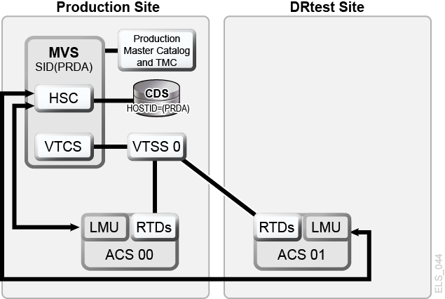
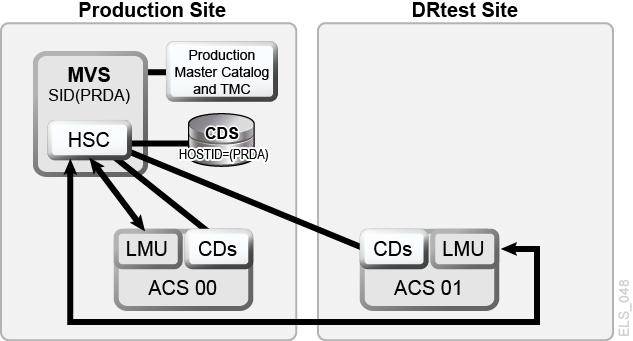
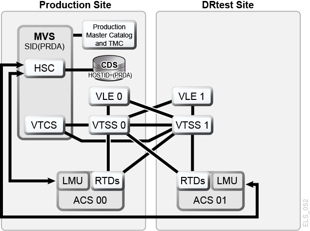
In Scenario 1, there is a single ACS at both the production and test sites, and "spare" VTSS(s) at the test site used solely for testing (no requirements to migrate or restore "spare" VTSS contents). In normal operations, the production site writes and accesses VTVs on VTSSs at the production site, and output VTVs are always migrated immediately and duplexed to separate MVCs, one in each ACS. Figure 7-1 shows the system for Scenario 1 before running the DRTEST utility.
Figure 7-1 Spare VTSS Configuration - Before Running the DRTEST Utility
Description of ''Figure 7-1 Spare VTSS Configuration - Before Running the DRTEST Utility''
Example JCL for Scenario 1
PRIMEPRD Step:
//DRTPRIME EXEC PGM=SLUADMIN,PARM='MIXED'
//STEPLIB  DD DSN=hlq.SEALINK,DISP=SHR
//SLSPRINT DD SYSOUT=*
//SLSIN DD *
DRTEST PRIMEPRD +
DRACS(01) DRVTSS(VTSS0) SPARE HOST(MVS1,MVS2)
CREATE Step:
//DRTCREAT EXEC PGM=SLUADMIN,PARM='MIXED'
//STEPLIB  DD DSN=hlq.SEALINK,DISP=SHR
//SLSPRINT DD SYSOUT=*
//SLSNEW1  DD DSN=hlq.DRTEST.SLSCNTL,DISP=(NEW,CATLG,DELETE),
//         UNIT=SYSDA,SPACE=(CYL,x)
//SLSNEW2  DD DSN=hlq.DRTEST.SLSCNTL2,DISP=(NEW,CATLG,DELETE),
//         UNIT=SYSDA,SPACE=(CYL,x)
//SLSNEW3  DD DSN=hlq.DRTEST.SLSSTBY,DISP=(NEW,CATLG,DELETE),
//         UNIT=SYSDA,SPACE=(CYL,x)
//SLSIN DD *
DRTEST CREATE NOUPDPRD +
DRACS(01) DRVTSS(VTSS0) SPARE HOST(MVS1,MVS2)
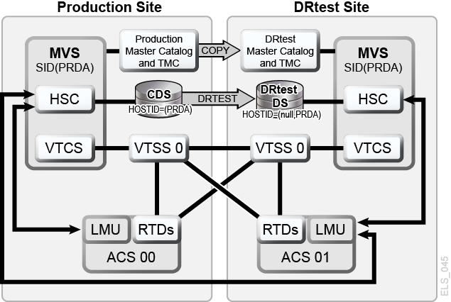
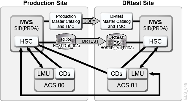
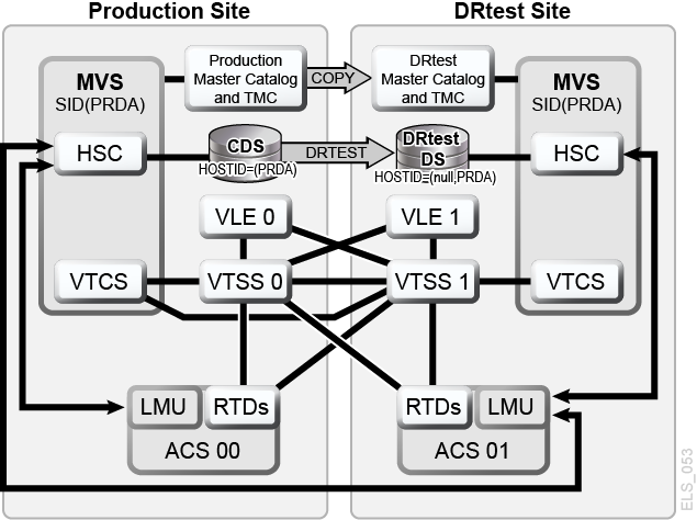
Figure 7-2 shows the system for Scenario 1 (spare VTSS at test site) after running the DRTEST utility.
Figure 7-2 Spare VTSS Configuration - After Running the DRTEST Utility
Description of ''Figure 7-2 Spare VTSS Configuration - After Running the DRTEST Utility''
Scenario 2: Production and Test Sites, ACS at Each Site, VTSS Takeover at Test Site
In Scenario 2, there is a single ACS at both the production and test sites, but no "spare" VTSS(s) at the test site used for testing. In normal operations, the production site writes and accesses VTVs on VTSSs at both sites, and output VTVs are always migrated immediately and duplexed to separate MVCs, one in each ACS. In this configuration, you must demand migrate to zero one or more VTSSs at the test site and vary these VTSSs offline to the production system, so testing can take over the required VTSS resources. In addition, one or more LPARs at the test site function as displaced production systems, running in parallel with the actual production systems. Both ACSs are online to the production system.
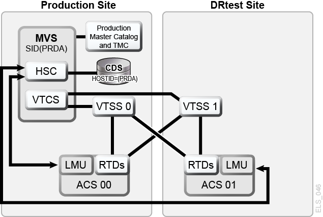
Figure 7-3 shows the system for Scenario 2 (VTSS takeover at test site) before running the DRTEST utility.
Figure 7-3 VTSS Takeover Configuration - Before Running the DRTEST Utility
Description of ''Figure 7-3 VTSS Takeover Configuration - Before Running the DRTEST Utility''
Example JCL for Scenario 2
CREATE Step Only, PRIMEPRD Run Previously:
//DRTCREAT EXEC PGM=SLUADMIN,PARM='MIXED'
//STEPLIB  DD DSN=hlq.SEALINK,DISP=SHR
//SLSPRINT DD SYSOUT=*
//SLSNEW1  DD DSN=hlq.DRTEST.SLSCNTL,DISP=(NEW,CATLG,DELETE),
//         UNIT=SYSDA,SPACE=(CYL,x)
//SLSNEW2  DD DSN=hlq.DRTEST.SLSCNTL2,DISP=(NEW,CATLG,DELETE),
//         UNIT=SYSDA,SPACE=(CYL,x)
//SLSNEW3  DD DSN=hlq.DRTEST.SLSSTBY,DISP=(NEW,CATLG,DELETE),
//         UNIT=SYSDA,SPACE=(CYL,x)
//SLSIN DD *
DRTEST CREATE NOUPDPRD +
DRACS(01) DRVTSS(VTSS1) HOST(MVS1,MVS2)
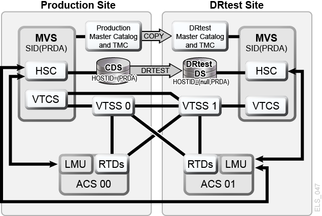
Figure 7-4 shows the system for Scenario 2 (VTSS takeover at test site) after running the DRTEST utility.
Figure 7-4 VTSS Takeover Configuration - After Running the DRTEST Utility
Description of ''Figure 7-4 VTSS Takeover Configuration - After Running the DRTEST Utility''
Scenario 3: Production and Test Sites, ACS at Each Site, No VTSSs
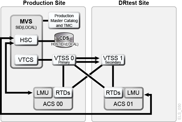
In Scenario 3, there is a single ACS at both the production and test sites, but no VTSS(s) at the test site used for testing. In normal operations, the production site writes and accesses tape data sets at both sites. Figure 7-5 shows the system for Scenario 3 (real-only configuration) before running the DRTEST utility.
Figure 7-5 Real-Only Configuration - Before Running the DRTEST Utility
Description of ''Figure 7-5 Real-Only Configuration - Before Running the DRTEST Utility''
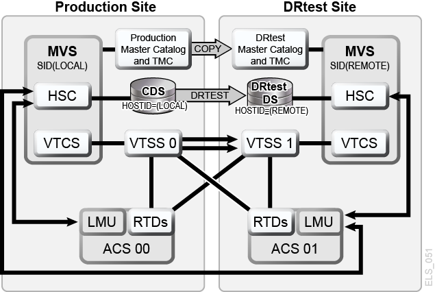
Figure 7-6 shows the system for Scenario 3 shows the system for Scenario 3 (real-only configuration) after running the DRTEST utility.
Figure 7-6 Real-Only Configuration - After Running the DRTEST Utility
Description of ''Figure 7-6 Real-Only Configuration - After Running the DRTEST Utility''
Example JCL for Scenario 3
CREATE Step Only, PRIMEPRD Run Previously:
//DRTCREAT EXEC PGM=SLUADMIN,PARM='MIXED'
//STEPLIB  DD DSN=hlq.SEALINK,DISP=SHR
//SLSPRINT DD SYSOUT=*
//SLSNEW1  DD DSN=hlq.DRTEST.SLSCNTL,DISP=(NEW,CATLG,DELETE),
//         UNIT=SYSDA,SPACE=(CYL,x)
//SLSNEW2  DD DSN=hlq.DRTEST.SLSCNTL2,DISP=(NEW,CATLG,DELETE),
//         UNIT=SYSDA,SPACE=(CYL,x)
//SLSNEW3  DD DSN=hlq.DRTEST.SLSSTBY,DISP=(NEW,CATLG,DELETE),
//         UNIT=SYSDA,SPACE=(CYL,x)
//SLSIN DD *
DRTEST CREATE NOUPDPRD +
DRACS(01) HOST(MVS1,MVS2)
Scenario 4: Clustered VTSSs with Production and DR Test Sites
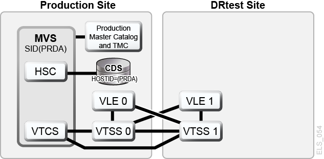
As shown in Figure 7-7, in normal operations, Scenario 4 is a Clustered VTSS configuration used for DR, with Production and DR Test sites cross-connected to the Production and DR Test ACSs. At the Production Site, VTSS0 is the Primary, and VTSS1 is the Secondary at the DR Test Site.
Figure 7-7 Primary/Secondary Clustered VTSS Configuration - Normal Operations
Description of ''Figure 7-7 Primary/Secondary Clustered VTSS Configuration - Normal Operations''
Example JCL for Scenario 4
CREATE Step Only, PRIMEPRD Run Previously:
//DRTCREAT EXEC PGM=SLUADMIN,PARM='MIXED'
//STEPLIB  DD DSN=hlq.SEALINK,DISP=SHR
//SLSPRINT DD SYSOUT=*
//SLSNEW1  DD DSN=hlq.DRTEST.SLSCNTL,DISP=(NEW,CATLG,DELETE),
//         UNIT=SYSDA,SPACE=(CYL,x)
//SLSNEW2  DD DSN=hlq.DRTEST.SLSCNTL2,DISP=(NEW,CATLG,DELETE),
//         UNIT=SYSDA,SPACE=(CYL,x)
//SLSNEW3  DD DSN=hlq.DRTEST.SLSSTBY,DISP=(NEW,CATLG,DELETE),
//         UNIT=SYSDA,SPACE=(CYL,x)
//SLSIN DD *
DRTEST CREATE NOUPDPRD +
DRACS(01) DRVTSS(VTSS1) SHARE HOST(MVS1,MVS2)
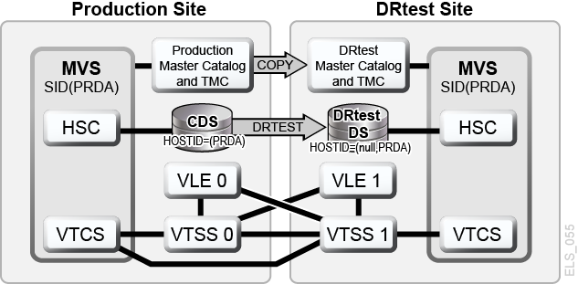
What if you want to use the DR Test Site for testing? Figure 7-8 shows the system for Scenario 4 during the DR test.
Figure 7-8 Primary/Secondary Clustered VTSS Configuration - During Test
Description of ''Figure 7-8 Primary/Secondary Clustered VTSS Configuration - During Test''
Scenario 5: Production and Test Sites, ACS and VLE at Each Site
In Scenario 5, there is a single ACS at both the production and test sites, but no "spare" VTSS(s) at the test site used for testing. In normal operations, the production site writes and accesses VTVs on VTSSs at both sites, and output VTVs are always migrated immediately and duplexed, one copy to an MVC in the ACS, one copy to a VMVC in the VLE. In this configuration, you must demand migrate to zero one or more VTSSs at the test site and vary these VTSSs offline to the production system, so testing can take over the required VTSS resources. In addition, one or more LPARs at the test site function as displaced production systems, running in parallel with the actual production systems. Both ACSs and VLEs are online to the production system.
Figure 7-9 shows the system for Scenario 5 before running the DRTEST utility.
Figure 7-9 VLE and ACS Configuration - Before Running the DRTEST Utility
Description of ''Figure 7-9 VLE and ACS Configuration - Before Running the DRTEST Utility''
Example JCL for Scenario 5
CREATE Step Only, PRIMEPRD Run Previously:
//DRTCREAT EXEC PGM=SLUADMIN,PARM='MIXED'
//STEPLIB  DD DSN=hlq.SEALINK,DISP=SHR
//SLSPRINT DD SYSOUT=*
//SLSNEW1  DD DSN=hlq.DRTEST.SLSCNTL,DISP=(NEW,CATLG,DELETE),
//         UNIT=SYSDA,SPACE=(CYL,x)
//SLSNEW2  DD DSN=hlq.DRTEST.SLSCNTL2,DISP=(NEW,CATLG,DELETE),
//         UNIT=SYSDA,SPACE=(CYL,x)
//SLSNEW3  DD DSN=hlq.DRTEST.SLSSTBY,DISP=(NEW,CATLG,DELETE),
//         UNIT=SYSDA,SPACE=(CYL,x)
//SLSIN DD *
DRTEST CREATE NOUPDPRD +
DRACS(01) DRVTSS(VTSS1) HOST(MVS1,MVS2) STORMNGR(VLE1)
Figure 7-10 shows the system for Scenario 5 after running the DRTEST utility.
Figure 7-10 VLE and ACS Configuration - After Running the DRTEST Utility
Description of ''Figure 7-10 VLE and ACS Configuration - After Running the DRTEST Utility''
Scenario 6: Production and Test Sites, VLE Only at Each Site
In Scenario 6, there is a single VTSS with a VLE attached at each site. The VTSS at the test site is not a spare and is used by the production site during normal operations. The output VTVs are always migrated immediately and duplexed to separate VMVCs, one in each VLE.
In this configuration, you must demand migrate to zero one or more VTSSs at the test site and vary these VTSSs offline to the production system, so testing can take over the required VTSS resources. In addition, one or more LPARs at the test site function as displaced production systems, running in parallel with the actual production systems. Both VLEs are online to the production system.
Figure 7-11 shows the system for Scenario 6 before running the DRTEST utility.
Figure 7-11 VLE Only Configuration - Before Running the DRTEST Utility
Description of ''Figure 7-11 VLE Only Configuration - Before Running the DRTEST Utility''
Example JCL for Scenario 6
CREATE Step Only, PRIMEPRD Run Previously:
//DRTCREAT EXEC PGM=SLUADMIN,PARM='MIXED'
//STEPLIB  DD DSN=hlq.SEALINK,DISP=SHR
//SLSPRINT DD SYSOUT=*
//SLSNEW1  DD DSN=hlq.DRTEST.SLSCNTL,DISP=(NEW,CATLG,DELETE),
//         UNIT=SYSDA,SPACE=(CYL,x)
//SLSNEW2  DD DSN=hlq.DRTEST.SLSCNTL2,DISP=(NEW,CATLG,DELETE),
//         UNIT=SYSDA,SPACE=(CYL,x)
//SLSNEW3  DD DSN=hlq.DRTEST.SLSSTBY,DISP=(NEW,CATLG,DELETE),
//         UNIT=SYSDA,SPACE=(CYL,x)
//SLSIN DD *
DRTEST CREATE NOUPDPRD +
STORMNGR(VLE1) DRVTSS(VTSS1) HOST(MVS1,MVS2)
Figure 7-12 shows the system for Scenario 6 after running the DRTEST utility.
Figure 7-12 VLE Only Scenario - After Running the DRTEST Utility
Description of ''Figure 7-12 VLE Only Scenario - After Running the DRTEST Utility''
Scenario 7: Clustered VTSSs (Tapeless) with Production and DR Test Sites
As shown in Figure 7-13, in normal operations, Scenario 7 is a Clustered VTSS (tapeless) configuration used for DR, with Production and DR Test site. At the Production Site, VTSS0 is the Primary, and VTSS1 is the Secondary at the DR Test Site.
Figure 7-13 Primary/Secondary Clustered VTSS Tapeless Configuration - Before Running the DRTEST Utility
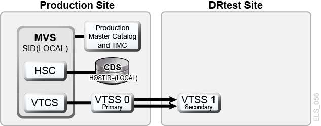
Description of ''Figure 7-13 Primary/Secondary Clustered VTSS Tapeless Configuration - Before Running the DRTEST Utility''
Example JCL for Scenario 7
CREATE Step Only, PRIMEPRD Run Previously:
//DRTCREAT EXEC PGM=SLUADMIN,PARM='MIXED'
//STEPLIB  DD DSN=hlq.SEALINK,DISP=SHR
//SLSPRINT DD SYSOUT=*
//SLSNEW1  DD DSN=hlq.DRTEST.SLSCNTL,DISP=(NEW,CATLG,DELETE),
//         UNIT=SYSDA,SPACE=(CYL,x)
//SLSNEW2  DD DSN=hlq.DRTEST.SLSCNTL2,DISP=(NEW,CATLG,DELETE),
//         UNIT=SYSDA,SPACE=(CYL,x)
//SLSNEW3  DD DSN=hlq.DRTEST.SLSSTBY,DISP=(NEW,CATLG,DELETE),
//         UNIT=SYSDA,SPACE=(CYL,x)
//SLSIN DD *
DRTEST CREATE NOUPDPRD +
DRVTSS(VTSS1) SHARE HOST(MVS1,MVS2))
What if you want to use the DR Test Site for testing? Figure 7-14 shows the system for Scenario 7 during the DR test.
Figure 7-14 Primary/Secondary Clustered VTSS Tapeless Configuration - During Test
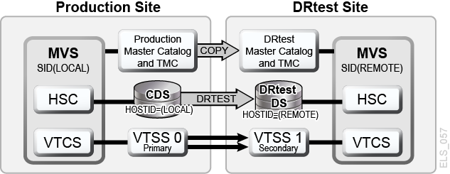
Description of ''Figure 7-14 Primary/Secondary Clustered VTSS Tapeless Configuration - During Test''