Before You Begin
Purpose
This tutorial walks you through the process of connecting to a Mobile Cloud Service (MCS) mobile backend and consuming APIs. The screen shots are from a Mac using an iOS simulator. You can follow the instructions and use it with an Android Emulator, too.
To complete this tutorial, you will configure and start Oracle Enterprise Pack for Eclipse (OEPE), then create a MAF application including features and an AMX page. Then, you'll connect to an MCS instance and import a custom API definition. You'll test the API from within OEPE to confirm it retrieves data, then create artifact classes to support accessing the API. Next, you create data controls to easily develop the AMX page. Since the API has security defined on it, you'll add authorization functionality to the MAF application. Finally, you'll deploy the application to a simulator/emulator and test that it retrieves incident records.
What Do You Need
To complete this tutorial you must, install and configure Oracle Enterprise Pack for Eclipse and either the Android SDK or Xcode 6 if you want to use iOS.
If you are using an iOS environment, you can use the following tutorial to set up the development environment: Set Up and Configure an iOS Environment.
If you are using an Android environment, you can use the following tutorial: Set Up and Configure an Android Environment.
| Required Files | Download Files
|
|---|---|
To see the completed application, click the Download button to download a zip of the completed application, and then unzip it in your OEPE documents folder. |
 |
Step 1: Start Eclipse and configure it to work with Mobile Application Framework applications
In this section, you start Eclipse (OEPE)and configure it to work with Mobile Application Framework applications.
-
Find and launch Eclipse.

-
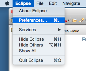
In OEPE, click Eclipse > Preferences.
-
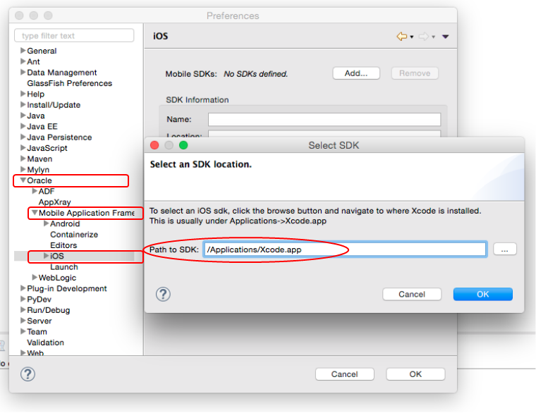
If you are using iOS, then in the Preferences dialog, Select Oracle > Mobile Application Framework > iOS and click Add. In the popup dialog, use the browse icon and select the path to your Xcode installation.
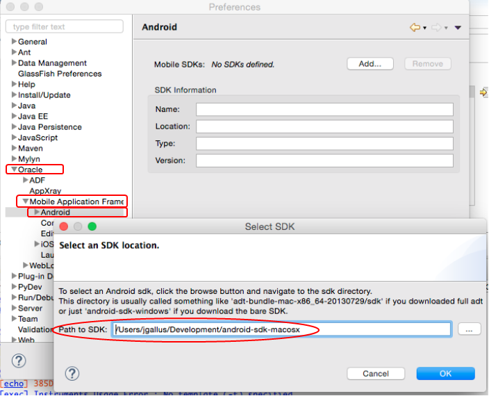
If you are using Android, then in the Preferences dialog, Select Oracle > Mobile Application Framework > Android SDK and click Add. In the popup dialog, use the browse icon and specify the path to your Android installation.
-
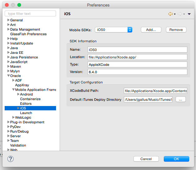
By specifying the SDK, OEPE completes the rest of the fields and they should look something like the following: Click OK to complete the configuration.
An iOS configuration.
An Android configuration.

-
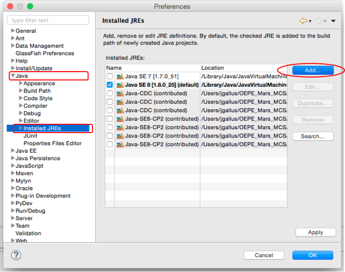
Then while still in Preferences, expand the Java node and select the Installed JREs.
Then, click the Add button
-
In the JRE Type, select Standard VM and click Next.

-
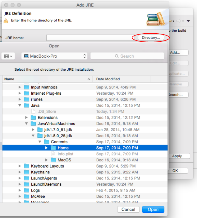
In the JRE Definition dialog, click the Directory button.
Navigate to the your root JDK 1.8 directory and select the it. Then, click the Open button.
-
Back in the JRE Definition, click Finish.

-
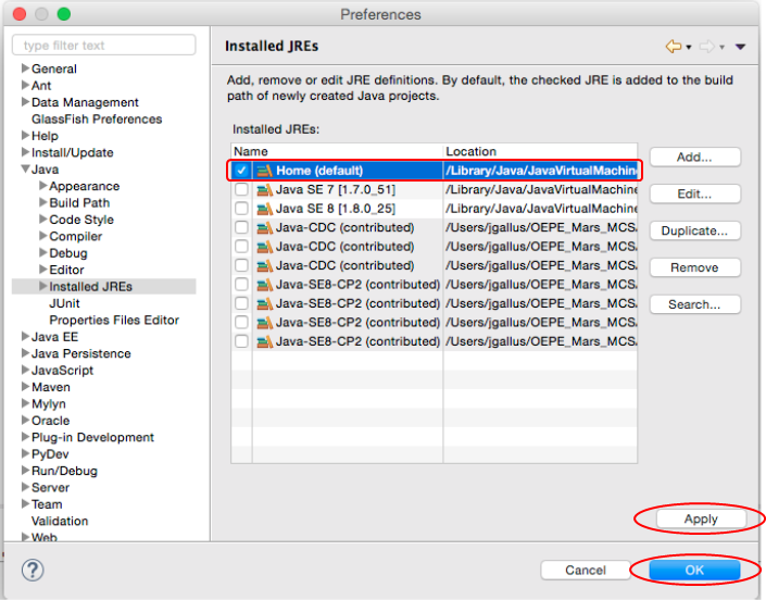
In the Installed JREs, select your new JRE to make it the default.
Then, click Apply and OK.
Step 2: Create a Mobile Application, a feature and a page to contain data
In this section, you create a MAF application, define a feature as the entry point to the application and then create an empty page to later contain incident data.
-
From the menu, select File - New - Other and then select MAF Application.

-
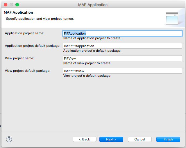
In the MAF Application dialog box, set Application display name to FiF.
Then, click Next.

-
The default values are fine here. Click Next.
-
Here is where you confirm the correct deployment target you would like to use. The options in the list correspond to what is defined in preferences.
Click Finish.

-
Next define a feature as the entry point to the MAF application
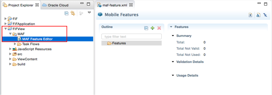
In the Project Explorer, expand the FIFView - MAF nodes and double-click the MAF Feature Editor. The editor displays the maf-feature.xml file, for you to edit, to the right of the explorer.
-
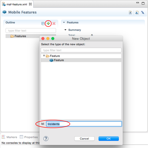
In the editor, click the green plus sign next to the Outline header.
In the New Object popup, set the Id to incidents.
Then click OK.
-
With the Incidents node selected, click the green plus sign again.
In the New Object popup, expand the Content node and select AMX page.
The default Id value is fine, so click OK.

-
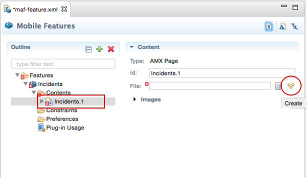
Quickly create a blank page. With the Incident.1 selected, click the three yellow stars to the right. If you hover over them, a Create tool tip will appear.
-
In the New MAF Page dialog, set the File name to incidents.amx and select only the header facet.
Click Finish.

-
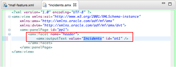
The Indidents.amx will appear in the editor.
Find the header facet and set the outputText value to Incidents.
Then, save all your work.
Step 3: Connect the MAF application to an MCS instance
In this part of the tutorial, you add connect your MAF application to an MCS instance, examine a RAML document and import it as a REST API.
-
To create a new cloud connection, click the Oracle Cloud tab and then click the Connect text.

-
Enter your MCS identity domain, username and password. Then click Finish

-
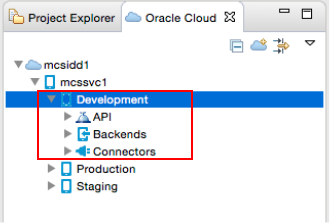
Once the the connection with MCS is completed, the instance is then interrogated and the components are displayed in the explorer.
Expand the nodes to reveal the Development API, Mobile Backends and Connectors.
-
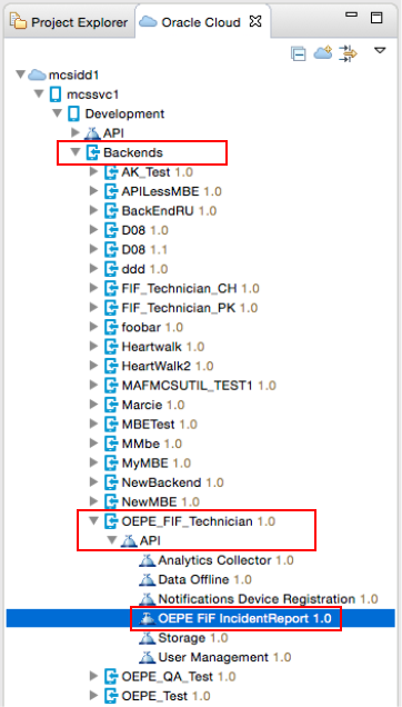
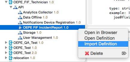
Expand the Backends - OEPE_FIF_Technician 1.0 - API nodes and select OEPE FIF IncidentReport 1.0.
-
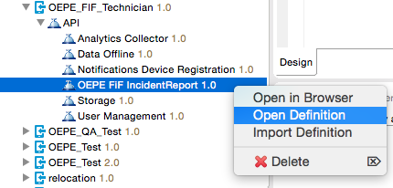
Then, right-click FIF_IncidentReport 1.0 and select Open Definition.
-
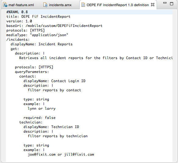
The RAML document for the API is fetched and displayed in the editor.
-
Next, import the RAML document into OEPE
RIght-click the OEPE FIF IncidentReport 1.0 and select Import Definition.
-
In the Backend Information page, notice that this API does not support anonymous access. This property and it's value are defined in MCS, on the API.
This step apply only to those with secured API, those with Anonymous access can skip and just click Next.

-
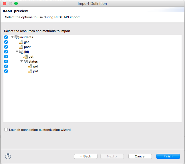
In the RAML preview, you can select the resources and methods you wish to include in the import.
For our purposes, keep them all selected and click Finish.
-
The REST API is displayed in the editor.
In the editor, select connection://OEPE_FIF_IncidentReport_1_0.
Then in the IDE, find the Connections view.
Expand the FIF node and double click the OEPE_FIF_IncidentReport_1_0 node.

-
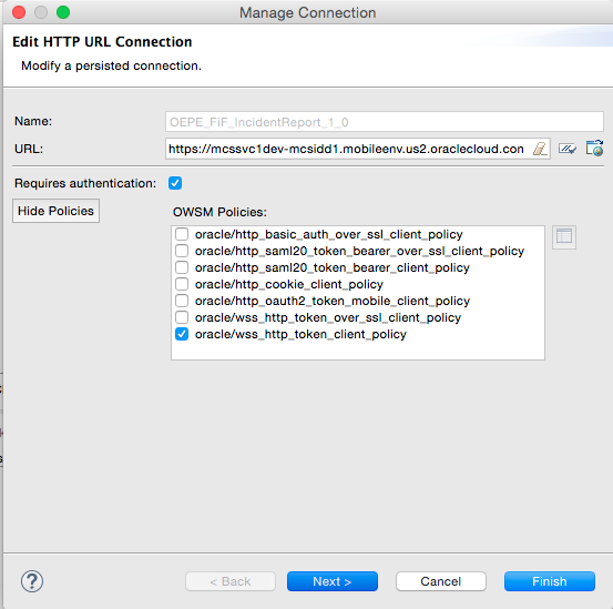
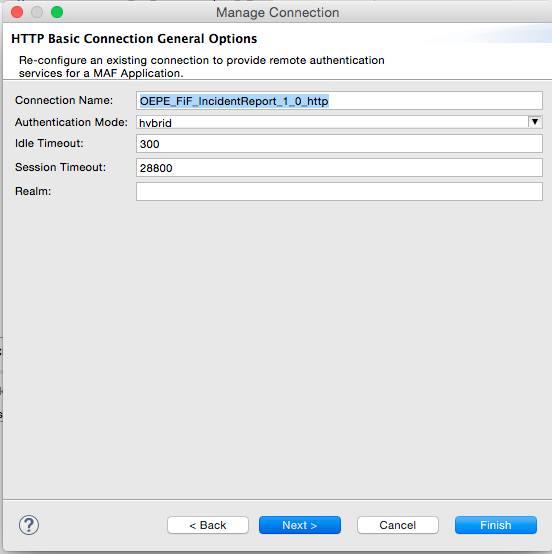
In the Manage Connection dialog you can see the MCS definitions.
Click the Show/Hide Policies button to view all of them. Like earlier, these properties are set in API definition of MCS.
-
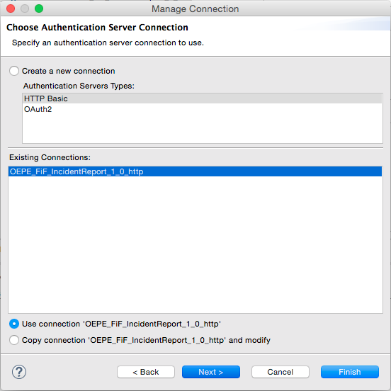
Click Next to see the connection or create new ones.
-
Click Next again, to see the Connection properties.
-
Click Next one more time to see the Login URL and Mobile Backend Id.
Click Cancel to close the dialog.

Step 4: Examine and generate classes to support the REST API
In this section,
-
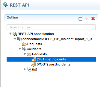
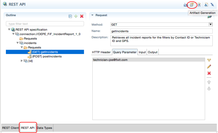
In the editor, expand connection://FIF_IncidentReport_1_0 - incidents - Requests.
The REST API specification and endpoints are displayed.
Select (GET) getIncidents Requests.
-
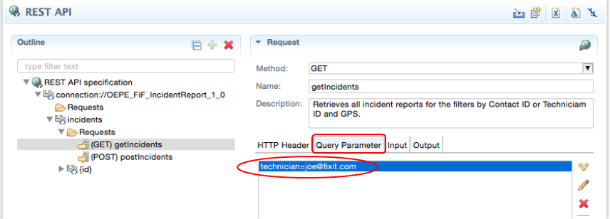
Switch to Query Parameter tab.
Delete contact and gps parameters to keep only the technician.
Then, edit the technician to set the Value to joe@fixit.com.
Save your changes.
-
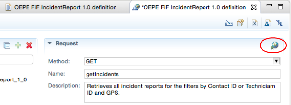
In the upper right corner, click the world icon to copy to a REST client.
-
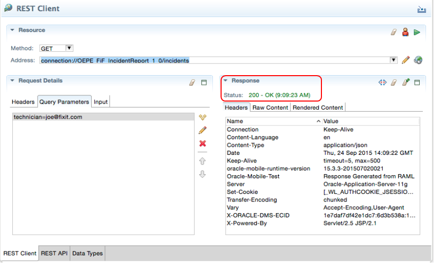
The data from the getIncidents request is copied to the REST Client page, including copying the address and the query parameters. In our case, the request (GET) getIncidents is automatically copied to the Address field.
In the upper right corner, click Send Request to execute the getIncidents.

-
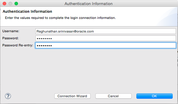
Since the API does not allow for anonymous authentication, you must enter a username and password to someone authorized to run the API.
Fill in the properties and click OK.
-
The request is sent and the response is shown on the right. A status of 200 should be returned.
-
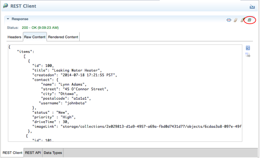
Click the Raw Content tab to see the data returned.

To get a better view of the data, click the maximize icon in the Response header.
When finished looking at the data click the restore icon to get back.
-
On the bottom of the editor, click the REST API tab.
Then, on the right, click the Output tab and select the Incidents.
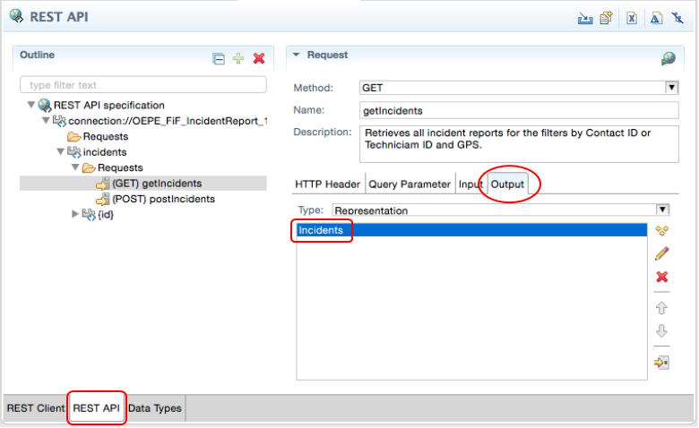
Let's examine the data types used by the Incident output.
On the bottom of the editor, click on the Data Types tab and then expand and select the Incidents node. Here you see details of the Incident, including it's attributes.

-
Next create the classes to support the API. At the bottom of the editor, again click the REST API tab.
Notice the icons in the upper right of the API. Click the second icon from the left, Artifact Generator. This starts the process to create all the Java classes you need to support the REST service.
-
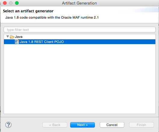
The Artifact Generator opens where you can select the type of artifact to create. In our case it's Java 1.8 REST Client POJO, which is the default.
Click Next.
-
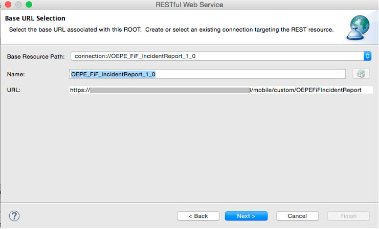
Here you can see the resource path, name and URL used while creating the classes.
Click Next.
-
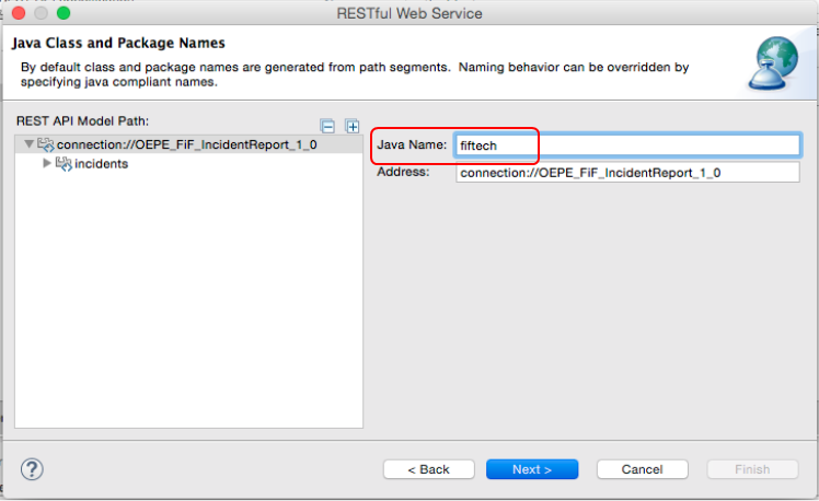
Here is where you can make class and package name changes. To keep things simple, set the Java Name to fiftech.
Then, click Next.
-
In the Generator setting, click Next.

-
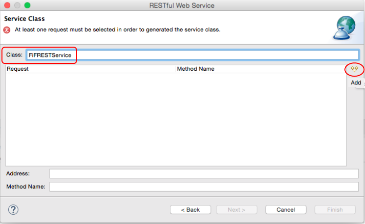
In the Service Class page, set the Class to FiFRESTService and then click the Add button on the right.
-
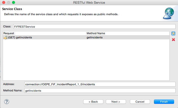
In the Select Requests popup, select the (GET) getIncidents node and then click OK.

-
Now that there is a request that can be exposed as a public method, you can click Finish.
-
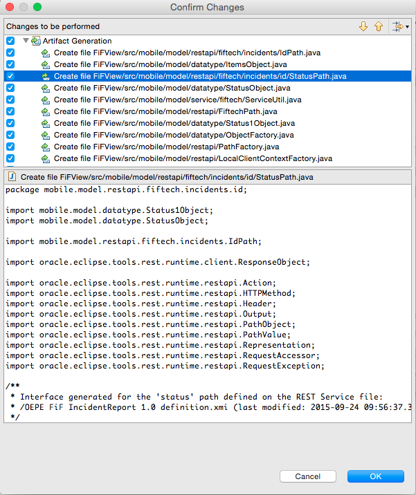
A Confirm Changes dialog is displayed showing all the things that will be done.
Here, on the top portion, you can select each of the classes and then in the bottom portion see the code that will be created.
Click OK.
-
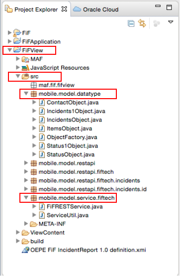
Click back on the Project Explorer tab and expand the FIFView - src - mobile.model.datatype and mobile.model.service.fiftech nodes to see the code that is generated.
-
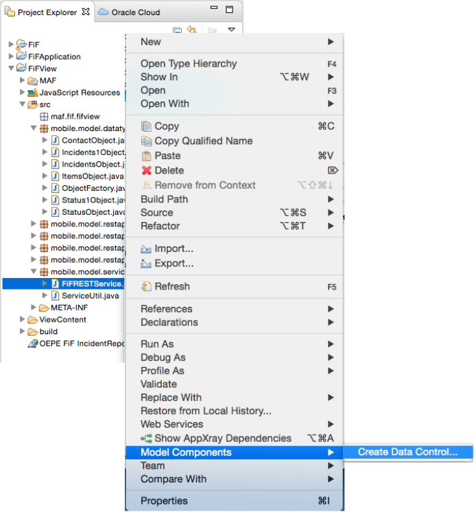
In the next couple of steps, create a data control to access the service from the page.
Right-click on FiFRESTService.java and select Model Components and then Create Data Control….
-
The default values in the Data Control Details pane are fine. Click Finish.

-
You are notified what files are affected.
Click OK to dismiss the notification.

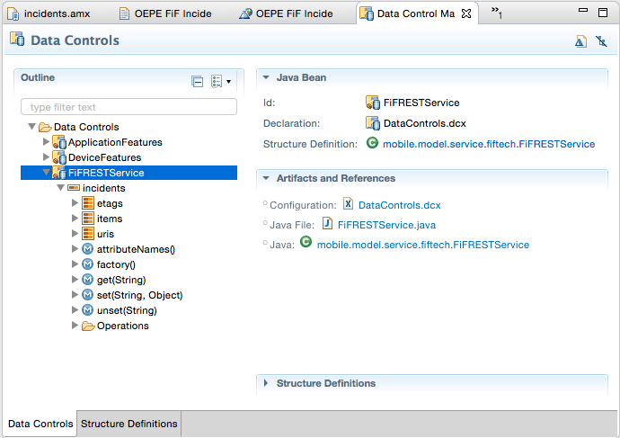
-
In the Data Controls area, you can expand the FiFRESTService data control and see the available collections and methods.
Step 5: Develop the Incident page by adding data and security
In this section, you include data components on the page to display incidents. You also enable the feature to use security and define a login server for the application to authenticate against.
-
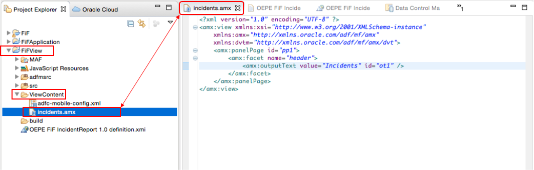
From the Project Explorer, expand the FiFView - ViewContent nodes and double click the Incidents.amx file
The AMX file is displayed in the editor.
-
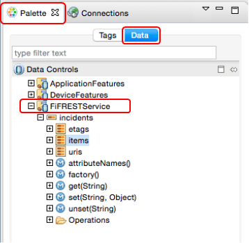
Click the the Palette tab, and the the Data sub tab. Here you see the Data Controls.
Expand the FiFRESTService - incidents nodes to expose the collections and methods.
-
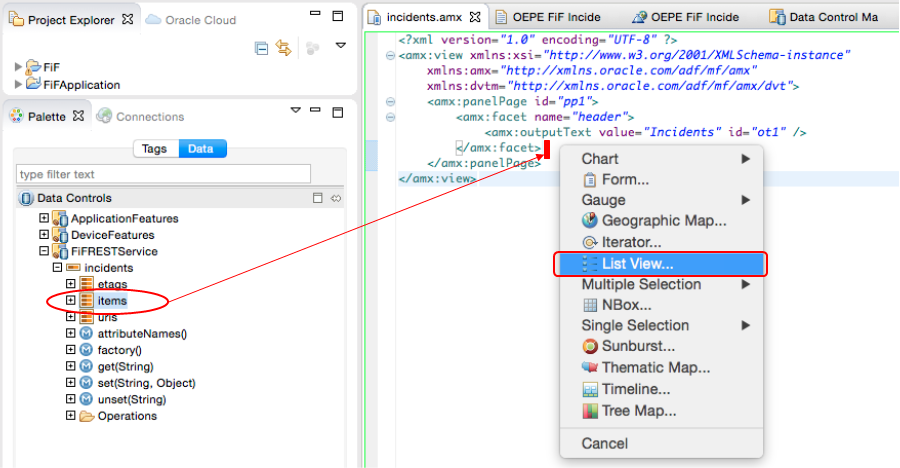
Drag the items collection onto the AMX page in the editor.
Drop them on the AMX page right after the </amx:facet> and before the </amx:panelPage>.
In the popup menu, select List View.
-
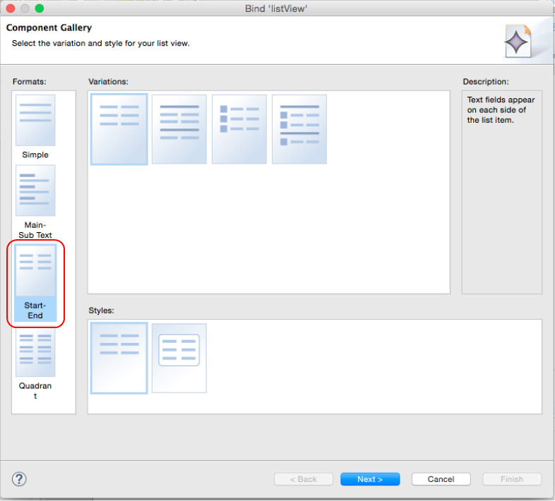
In the Component Gallery, select the Start-End Format.
Then click Next.
-
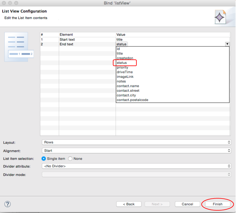
In the List View Configuration page, use the dropdown and set the Start text to title and the End text to status.
Leave the rest of the values at their default values and click Finish.
Then, Save all your work.
-
This step apply only to those with secured API. Those with APIs with Anonymous access can skip the remaining steps in this section and continue on to Step 6: Create a configuration file, deploy and test the application.
Since the API employs security, we need to include security as part of the feature.
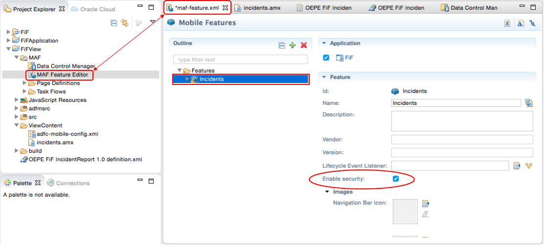
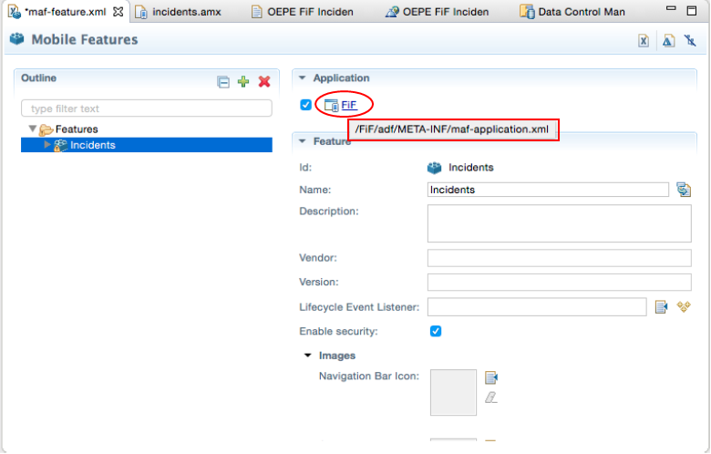
Reopen the MAF Feature Editor (maf-feature.xml) and select the Incidents feature.
Select the Enable security checkbox. Then, Save your work.
-
Now that the feature is flagged to be secure, configure the application for security. You enable security for the application in the maf-application.xml file.
From the Mobile Features page, move the mouse over the application name, in this case FIF, and you'll see the location of the file.
-
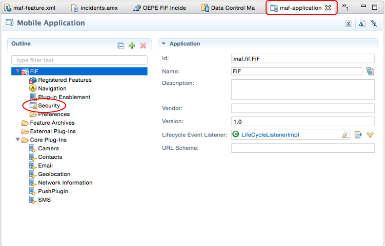
Click the icon just to the left of the name and you are taken to the Mobile Application (maf-application.xml) page.

Here you can see the details of the application, including security. Notice the red X by the Registered Features. This signifies that security is required for a feature, but had not been defined in the application.
-
Click the Security tab to set up the server details.
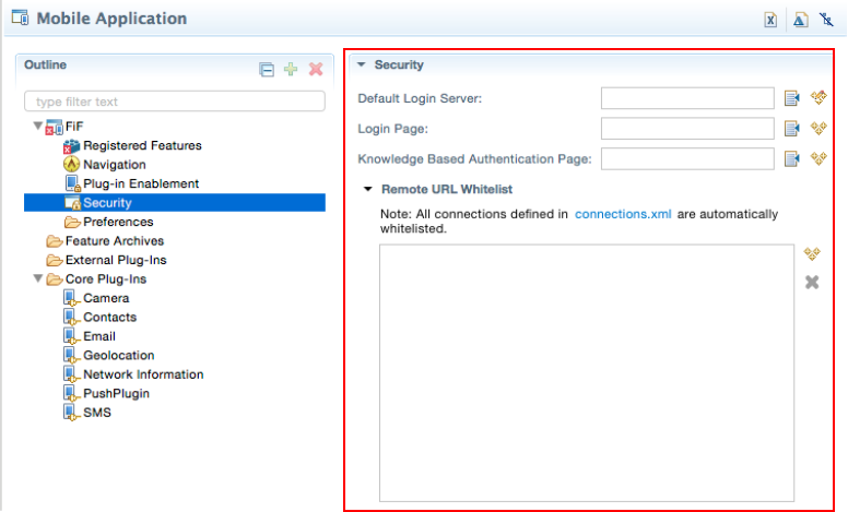
-
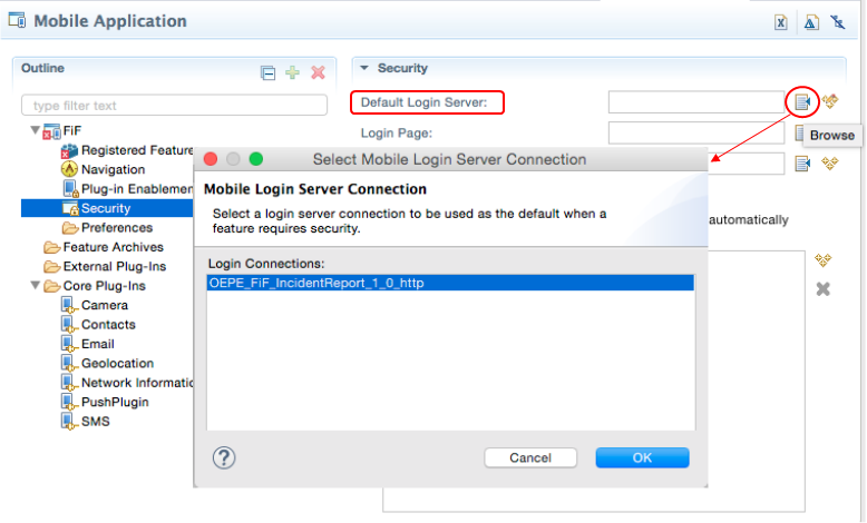
Click the Browse button next to the Default Login Server property. Here you can select a connection to MCS, or any other server, where the authentication is taking place.
Select your OEPE_FiF_IncidentReport_1_0_http connection and then click OK.
-
Save all your work.
Step 6: Create a configuration file, deploy and test the application
In this part of the tutorial, you create a deployment configuration file for your simulator/emulator, then deploy and test the application.
-
The first step in the deployment process is to create a configuration file. For our purposes, we'll use a debug configuration.
From the OEPE toolbar, click the 5th icon from the left - Debug.
In the drop down menu, select Debug Configuration.

-
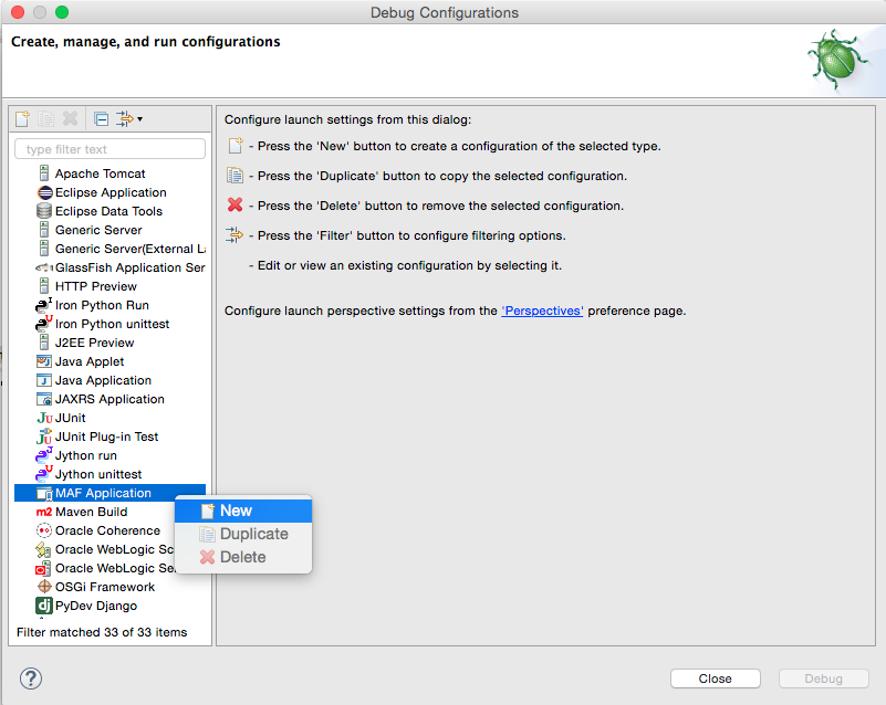
In the Debug Configuration, select the MAF Application node, then right-click.
From the menu, select New.
-
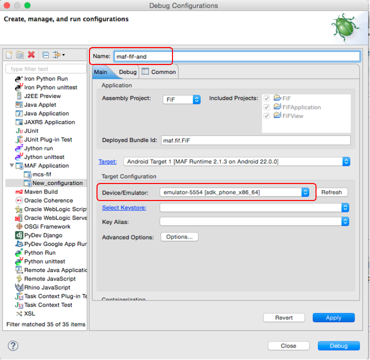
Set the name to mcs-fif and then if you are using iOS, specify a Simulator Name.
Then, click Apply.

If you are using Android, ensure the emulator is set.
-
Click the Debug button to start the deployment process.
You can monitor the progress in the Console until it completes.

-
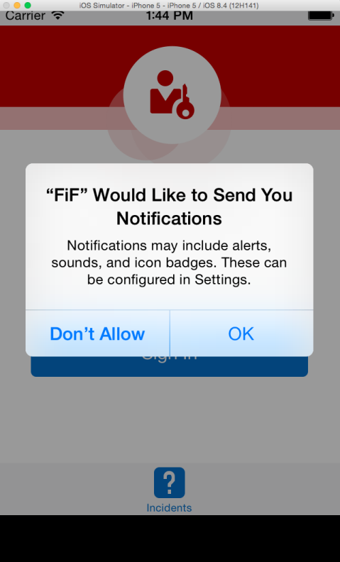
The simulator/emulator will start, followed by the FiF application.
You may be prompted about sending notifications. Click OK to continue.
-
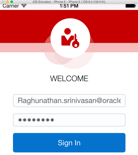
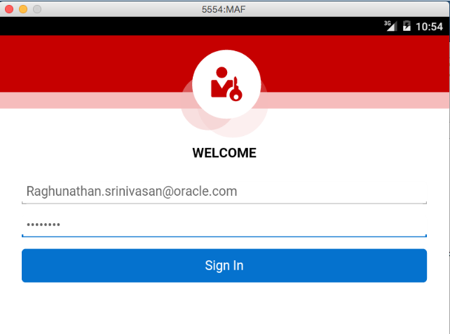
Like earlier when used the REST Client to test, you need the username password for the FiF Technician granted access to run the API.
Enter the username and password.
Then, click Sign In.
In an iOS Simulator.
In an Android Emulator.
-
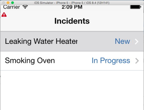
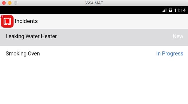
The application connect to MCS and authenticates against the API you want to run, in this case Incidents.
The API the retrieves data using the API and displays it on the page created using the data controls
In an iOS Simulator
In an Android Emulator.
At this point the tutorial is complete. You have created a Mobile Application Framework application that consumes and uses Mobile Cloud Service components.